Proposal Research for design 05
5.1 Approach in the proposal of a Design framework for Timber top-ups
5.2 Processes followed in the design of a timber top-up
As seen in Section 2, there needs to be more literature about construction methods for timber top-ups in existing RC buildings. As seen in Section 3.5, a reason that might relate to the use of timber in structures for highrise constructions is a relatively recent practice, which means that its application is still experimental. Consequently, this prompts a challenge to approach the research question: How to increase the area capacity of existing Reinforce Concrete structure buildings and extend their lifespan by using timber top-ups? as there are limited documented data and literature that would help to analyze what are its benefits and limitations of Timber Top-ups.
Moreover, insufficient literature regarding topping up timber directly affects SQ.3: How to make topping up in the decision-making for stakeholders when facing demolishing/building new? No theoretical background is available to base the feasibility of a top-up timber structure. Therefore, the graduation project focuses on producing specific approaches aiming to fill this gap :
First, a proposal of a design framework that will document the design process necessary to assess the feasibility of timber Top-up. Furthermore, to define the inputs and hard constraints necessary to evaluate the possibilities and limitations of the strategy.
And second, the design of a timber top-up structure for the study case described in Section 4.1.3. The reason for designing a specific structure for the case study is to include, from a practical perspective add, inputs to the design framework. Moreover, to ensure this framework is coherent.
Therefore, In the case of the graduation project, the design will be conducted in parallel, as relevant findings might appear during the design of the top-up that complements the design framework.
5.1 Approach in the proposal of a Design framework for Timber top-ups
A design framework is a step-by-step definition defined in a diagram that defines the inputs and outcomes necessary to assess an objective. In the case of the graduation project, a diagram that aims to approach SQ. 3 by documenting the steps in the design of a timber top-up.
Therefore, a graphical tool capable of organizing processes is required to construct the design framework. In his book: “Workflow Modeling: Tools for Process Improvement and Application Development,” Sharp & McDermott (2009) states that a swimlanes diagram provides a clear and structured view of how various activities are performed by different individuals, teams, or departments involved in the process. In this case, assuming the decision-making of a Timber Top-up requires the analysis of different stakeholders from different fields, it might be an effective graphical tool to organize the process.
As defined by the author, the process starts by listing the steps of the process. To do so, a diagram called the “augmented scope model” (Diagram 3), aims to recognize the success of a process by understanding and addressing the broader context in which the process operates. Moreover, this model allows for a more comprehensive process analysis by considering the interdependencies, inputs, outputs, and interactions between the core process and its surrounding activities. The defined steps for the design framework to analyze the feasibility of timber top-ups are defined as follows:
The Collect stage comprises a series of processes to establish the foundation for analysis by developing a contextual understanding of the case study. It involves gathering all available data relevant to the subject matter. Additionally, this stage may generate additional information necessary for subsequent stages but is currently unavailable.
The Analysis stage involves filtering and analyzing the data collected during the previous stage. This stage aims to organize the data based on its relevance and importance in the decision-making process for Timber Top-ups.
Definition stage: In this stage, the hard and soft constraints are defined based on the data filtered and organized in the previous analysis stage. These constraints are requirements that the Timber Top-up proposal in the case study must meet. The defined constraints can include quantitative and qualitative aspects, which will be evaluated in the following stages.
Propose stage: In this stage, the defined hard and soft constraints act as input for designing a Timber Top-up for the case study. Considering a broad range of constraints during the design process enables more accurate results in the subsequent evaluation stage, resulting in a more precise and well-supported proposal. Moreover, this approach allows for exploring multiple architectural or engineering proposals in different scenarios, facilitating a comprehensive evaluation.
Evaluate stage: The previously proposed scenarios undergo testing in the evaluation stage. This involves assessing the performance of the defined criteria for each iteration using digital tools. Parametric design tools can be employed in this assessment to evaluate different iterations and optimize the results in each proposed scenario.
Diagram 16. Swimlane diagram for the Design framework in the desition making for timber top-ups.
Results stage: In this final stage, the evaluation process yields preliminary results for each scenario based on the specified criteria. These results are then compared across the different scenarios to gain insights into their potential and constraints. Through this comparison, a discussion can be facilitated to assess the feasibility of implementing a top-up solution for the specific case study.
Based on the augmented scope model illustrated in Diagram 3, a swimlane diagram is proposed where the are specified necessary activities to fulfill the goal. As can be seen in Diagram XX, each dependency to be analyzed for topping up is assigned a "swimlane" or a horizontal lane. These swimlanes are typically arranged vertically, representing the process's sequence of activities or steps where the responsibilities of the different dependencies are visually separated, allowing for a better understanding of the handoffs and interactions.
It is relevant to mention that the design process for the graduation project will primarily focus on the dependencies of Structural Mechanics and Circular Design. However, it's important to note that analyzing the feasibility of a Timber Top-up is not limited to these two fields alone. Considering additional constraints from other fields of study can lead to a more specific and well-founded proposal. Moreover, the design framework should include the analysis of other relevant dependencies, such as Urbanism & Landscape, Architecture, and Management, which may contribute significant findings to the process. Although these areas of knowledge will be mentioned in this research, their development should be further explored in future studies.
5.2 Processes followed in the design of a timber top-up
The following section describes the processes illustrated in the design framework in diagram XX. Moreover, in parallel, the design process of the timber top-up for the Gillisbuurt residential complex will be differentiated in italic text font.
5.2.1 Collect
The first step in the design Framework focuses on collecting the historical records, drawings, and building details in the case study. This involves researching to locate and obtain relevant historical records, such as construction documents, architectural plans, and engineering drawings concerning the target building to be Topped Up. Collect historical records of structural drawings and existing detailing.
Besides gathering the architectural data, gathering information related to the concrete elements' composition and dimensions is relevant. These data serve as a valuable resource for understanding the structural characteristics and constraints of the building, which will help in the subsequent stages of the assessment to design the timber top-up structure.
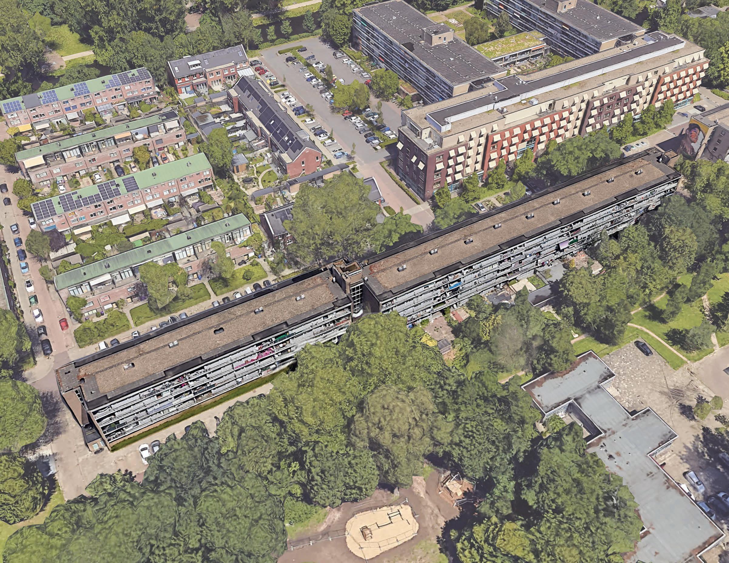
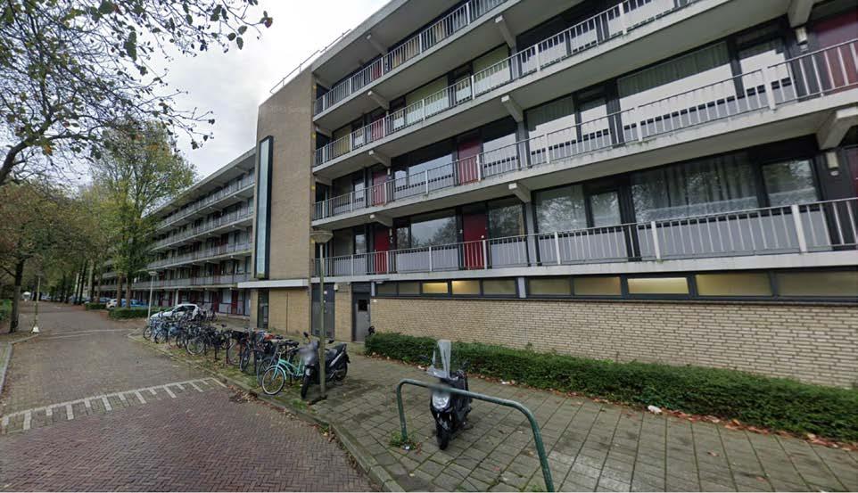
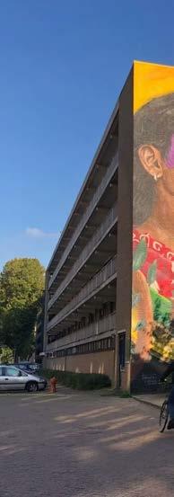
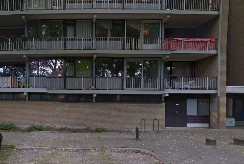
Applied to the case study, The historical archive of the city of Delft (Stadsarchivedelft) keeps all the available documentation related to the city’s buildings. Moreover, for the case study building mentioned in Section 4.1.4: Walkin apartments in Chopinlaan Street (block O&P), there was found an extensive database with the original Architectural drawings (Plans, sections, and facades) as the original structural proposal (composed of structural plans, details, sizes of components, and some specifications of the materials used back then in the construction). All of the relevant data that might be useful for the design of the Timber Top-up will be mentioned in the following section, 5.2.2 Analyse. However, all of the gathered information found in the archive of the city of Delft can be reviewed in the appendix section (Appendix A) at the end of the report.
On-site inspection of the existing structure.
The next activity in the process involves conducting an on-site inspection of the building to gather field information; this activity aims to validate and inspect the building drawing and specification with reality.
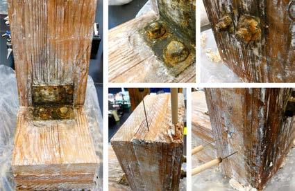
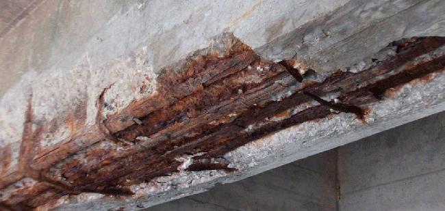
Moreover, examine the structural physical characteristics and conditions. Furthermore, if technically possible, as in The case study of the Karel Voorman building described in Section 2.4.1, destructive and non-destructive testing can be performed in the structure to validate the main physical characteristics of the structural components such as beams, columns, and foundations, paying attention to any visible signs of deterioration, damage, or structural weaknesses.
Applied to the case study, an on-site inspection was conducted at the Walk-in apartments on Chopinlaan Street in blocks O & P. The purpose of the inspection was to visually assess the overall project, including one of the housing units. Due to the building being occupied, it is impossible to conduct structural testing to determine the physical characteristics of its components. However, based on the visual inspection during the visit and the fact that the building is functioning normally, it can be inferred that the structure is in good condition. Therefore, for this graduation project, it will be assumed that the processes involved will produce acceptable results regarding the structural integrity of the components.
Analysis of the design codes: Timber and concrete.
The following process involves determining and analyzing the local structural codes and regulations that apply to the design of the timber Top-up structure. Particularly those related to timber construction and structural engineering, to ensure that further steps for the design intervention are aligned with the local safety standards.
In the Netherlands, the design and construction of structures are governed by the
structural code Eurocode. Moreover, the NEN-EN 1995-1-1 (EC5) and NEN-EN 19941-1 (AC4) standards are proposed to design timber and composite structures.
In addition to Eurocode, the Building Decree (Bouwbesluit) sets out the minimum requirements for building safety, health, usability, and energy efficiency. Moreover, this code states the norms required to ensure fire safety and other aspects relevant to the combination of timber and concrete in structures.
Besides the information provided by the Delfts historical archive and the report: “Integral exploration of the Buitenhof area-opportunity cards” mentioned in Section 4.1.1 by the Delfts Geemente, no other relevant published data was found during the conduct of this research about the case study.
However, some projects conducted by the University of Delft by the S.W.A.T studio from the Building Technology Master track have researched and performed proposals to improve the social conditions of the neighborhood's inhabitants by proposing specific interventions in the public space. These testimonies were included in Section 4.1.1. and might help in further steps as input for the architectural design.
5.2.2 Analyse
Analysis of the existing building, including the structural typology, components, and materials.
Starting the analysis stage, this first process aims to characterize the existing building followed to determine the load-bearing capacity of the whole structure to understand its current state and identify its strengths and limitations. Moreover, to understand the configuration of the existing structure to intervene.
The analysis of the case study building is as follows described: Walk-in apartments in Chopinlaan Street (block O&P) in Gillisbuurt.
Year of construction: 1968
Construction company: Ir. E.J.A CORSMIT c.i
Use: Residential dwellings.
Number of stories: G+4.
Number of households and typologies: 64 households, 75 m2 each, with a terrace of 11.2 m2 facing South.
Orientation: North-South.
Overall dimensions: 162 m (length), 12,89 m (width), 14 m (Height).
• Characteristics of the existing structure
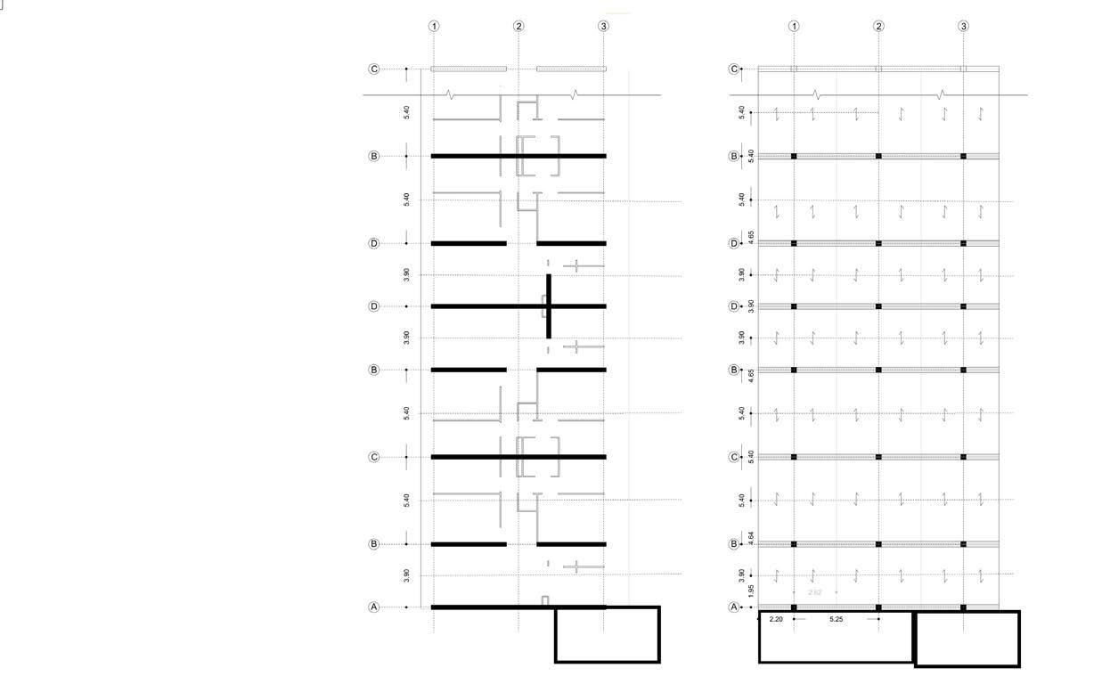
The Gillisbuurt blocks have a structural system that consists of in-situ casted concrete frameworks connected by RC prefab floors, creating a strong and stable framework. The construction is based on a grid pattern with center-to-center distances of 3.90 meters and 5.40 meters. At the same time, the floor-to-floor height is 2.8 meters, with a variable depth between 10.64 meters and 9.74 meters, depending on the type of structural cell. The casted walls and prefab slabs in the floors have a thickness of 180 mm.
Each framework accommodates 80 cells, of which 70 are designated for dwellings. The remaining ten cells are on the ground floor and serve as storage and utility rooms.
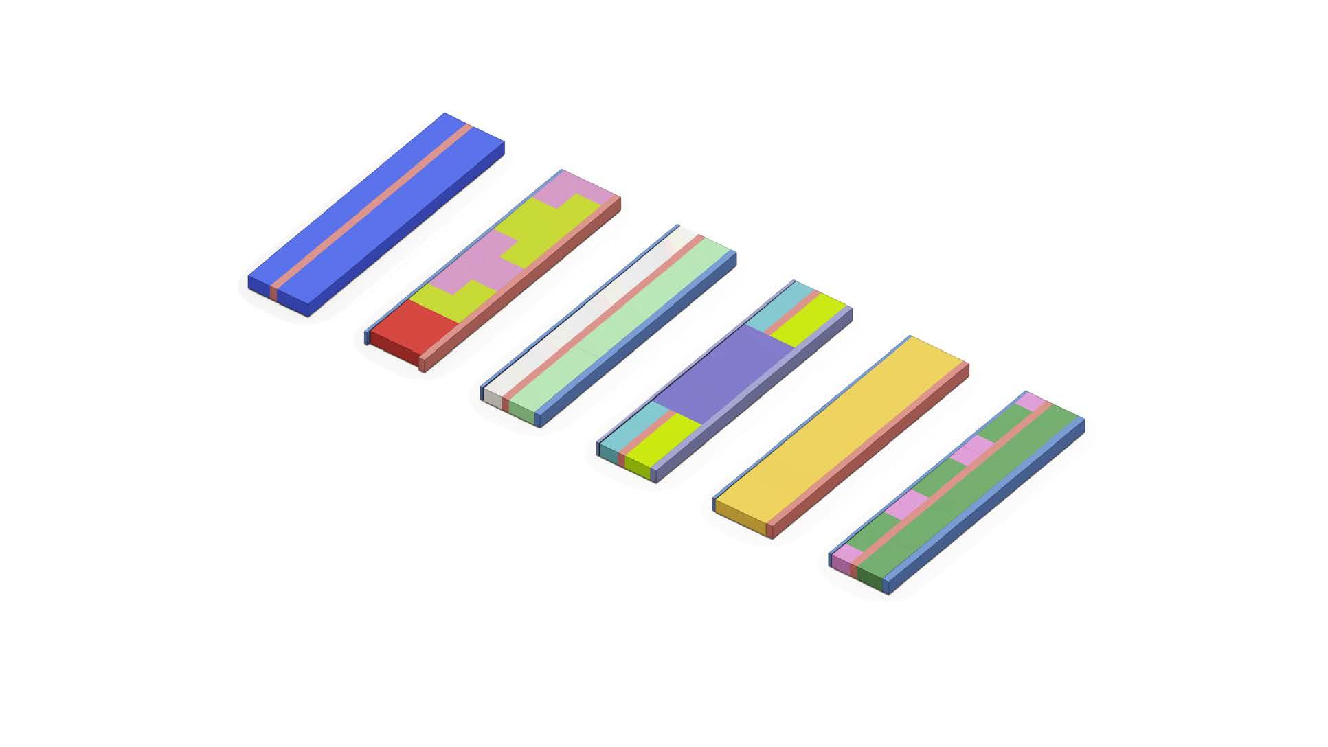
• components and materials:
As mentioned in the previous section, the main components of the existing concrete

structure are two: The concrete prefab slabs that were produced back then by the company E.J.A CORSMIT c.i in their facilities in Bergambacht in Zuid-Holland. And the cast in situ walls with steel reinforcement.
According to the archived structural specifications (Appendix A), the specified concrete for the project was K300. In current standards, specifically NEN-EN 1992 and Eurocode 2, this specification translates to a concrete type known as C19/22. This concrete type primarily consists of Portland cement, sand, aggregates, and water in a mix ratio of 1:2:3.For the reinforcement steel bars, a reference code QRn48 was used, indicating steel with a yield strength of 480 MPa.
In addition to the main structural components, the terraces, gallery access, and supporting cantilever beams are prefabricated elements that adhere to the specifications mentioned above. The comprehensive list of components and their corresponding composition of raw materials can be found in Diagram 5.
Parametrization of the existing model as a base for the analysis
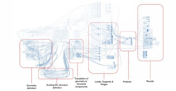
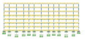
In the following process, all the gathered data (construction drawings, architectural plans, technical reports, literature, and any other available documentation in the previous stage) is sorted and analyzed to Parametrize the existing building into a 3d model using Rhino 7 and Grasshopper. Moreover, define the parameters to be assessed and controlled in the proposal stage.
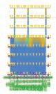
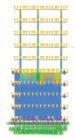
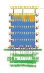
In the Study case, a script in Grasshopper was developed based on the available planimetry of the structure. One of the main characteristics of the script was the possibility of removing the number of layers of the RC structure with a slider, as seen in Image XX.
Calculation of embodied energy and embodied carbon of the existing structure.
The subsequent step involves the analysis of the building's life cycle, specifically focusing on the Upfront embodied carbon throughout its entire first cycle and on understanding the environmental impact of the building's construction, operation, and end-of-life potential.
Therefore, factors such as the energy intensity of the materials, the distance traveled during transportation, and the energy required for on-site construction activities are considered.
In the study case, this analysis was achieved by using the Granta Edupack software with the EcoAudit feature, in which, by inputting the components of the existing structure, it was possible to obtain the current CO2 footprint of the project. Moreover, as seen in graph XX, the feature of EoL potential is used to analyze three possible scenarios to process concrete: Downcycle, recycle, and Reuse.
2023
It is essential to clarify that the values used by Granta Edupack and illustrated in chart XX are based on a database fed with numbers taken from literature review on different research papers about LCA analysis. Therefore, these numbers are reference values that might be further compared with a specific LCA of the project that would consider all the construction variables in the construction of the building.
Analysis of the structural capacity of the existing structure and its components. This analysis helps determine the load-bearing capacity of the whole structure to understand the building's current state and identify its strengths and limitations. Moreover, this analysis looks to compare the structural capacity of the existing building to support and transfer the expected loads and design requirements of the proposed timber top-up structure.
It’s relevant to highlight that in some cases in The Netherlands, RC structures might be over-dimensioned to bare the current load cases to comply with safety factors of out-to-date design codes, conferring the existing structure an additional capacity to withstand and transfer some additional loads.
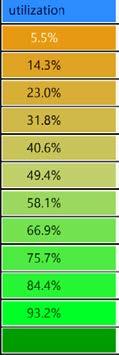
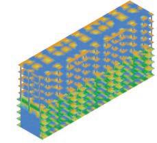
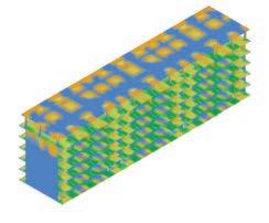
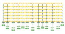
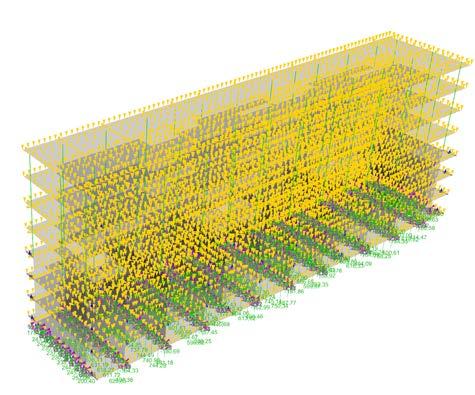
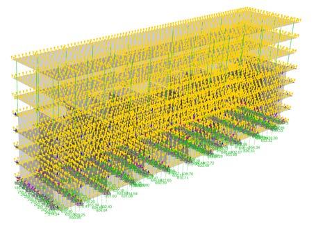
In the study case, the structural feasibility of top-up relies heavily on the structural capacity of the concrete vertical components of the structure. Therefore, using the software Karamaba 3d, the structural utilization of the RC walls in the existing structure is analyzed, as seen in Image XX.
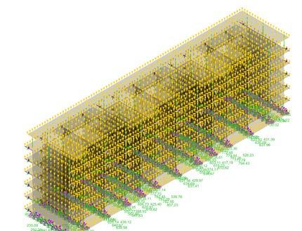
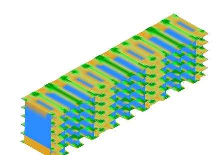
As seen in the graph, walls have an overutilization capacity in those elements allowing them to withstand a major load case. Further research is needed to determine if this over-dimensioned capacity is also present in the foundation piles. It's worth noticing that the loads can increase by 40% in the largest load cases.
5.2.3 Define Definition of structural assumptions.
The next stage in the process focuses on defining the structural assumptions based on hypothetical scenarios of building Timber Top Ups in the existing structure. Moreover, to make a guess based on previous knowledge in structural design about how the entire structural system will work, especially considering the impact of the timber top-up on the existing reinforced concrete structure.
In the study case, these assumptions, along with predefined structural parameters, include as seen in Figure 16:
a. Constructing a lightweight structure on a rigid concrete base may result in concentrated tension stresses, particularly in the reinforced concrete walls beneath the timber top-up.
b. Timber top-ups at certain heights are exposed to significant wind loads compared to the original building, necessitating stabilizing elements to withstand and transfer horizontal loads.
c. To avoid creating differential load reactions in the foundation that could destabilize the structure, the weight and loads of the top-up should be uniformly distributed, ensuring even loading of the existing structure.
Definition of load case scenarios and structural situations.


This stage focuses on determining the specific load cases that will be considered during the design of the timber top-up structure. Moreover, these load cases are defined based on factors such as the structure’s intended use, location, and architectural constraints. Therefore, various load scenarios can be proposed throughout the lifespan of the second cycle of the building.
The defined load cases are also utilized in the preliminary dimensioning for the structural elements. This means that the loads determined in this stage are also used to estimate the initial sizes and capacities of the timber components.
Figure 17 illustrates the load case scenarios used in the project based on the defined Live loads, dead loads, snow loads, and wind loads for the intervention. The calculation for the wind load is explained in detail in Appendix D.
Definition
of structural criteria based
on the Limit state design method (LSD).
This stage aims to select and analyze structural criteria derived from the Limit State Design method, commonly used in structural codes like Eurocode. This method encompasses structural criteria such as Yield strength, buckling, stability, fracture due to fatigue, deflection, vibration, fatigue, and fire resistance in the Ultimate limit state (ULS) and service limit state (SLS).
The aim is to identify the most relevant criteria that will enable a preliminary structural assessment for evaluating the feasibility of timber top-ups. By examining and sorting these criteria, the design team can establish a comprehensive framework for assessing the structural viability and performance of the proposed timber top-up, ensuring compliance with safety and design standards.
For the case study, five criteria are decided to be evaluated, the first three for the RC existing structure related to Ultimate Limit State (ULS):
Reactions in the foundations after Toping-up: To evaluate if there are differences in the reactions of the foundation after and before topping up.
Utilization of the components in the concrete structure: To evaluate if the utilization of the concrete elements is in admissible ranges after the top-up intervention.
Analysis of concentrated stresses in the RC walls: To evaluate if affectation is due after the top-up placement.
And there regarding the structure of the timber top-up:
ULS - Utilization of the Timber top-up components (maximum shear and moment): To determine the component’s response to the structural requirements in the load case scenarios.
ULS – Fire resistance for the top-up to withstand 120 minutes. As can be seen in Graph XX
SLS - Deflection limit: To control the displacement of structural components of the top-up are in admissible values.
Definition of circular design principles
The next step in the process focuses on determining criteria that will be utilized during the proposal stage to facilitate the transformation of an existing building using circular principles for the intervened building. To establish these criteria, two specific frameworks from two researchers are proposed and used as a reference:
First, the 10 "R" framework of sustainability of Potting et al. (2017) (as seen in Figure 3 on page 10), where the authors characterize key principles of circular design to transform an existing building using circular principles such as: Reduce, Reuse, Recycle, Repair, and Recover of the components.
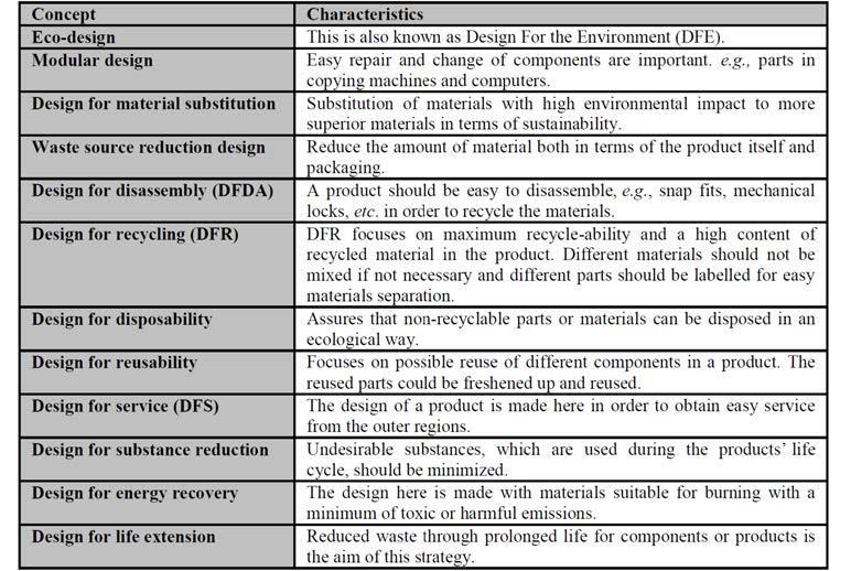
Second, the work of Ljungberg, L. Y. on Materials Selection and Design for the Development of Sustainable Products (as seen in Table 6 shows a brief theory recap of LSD focusing on the main relevant criteria assessed in the Ultimate limit design (ULS) and Service limit state (SLS).), where are provided valuable insights into sustainable material choices and design strategies that can be applied to enhance the circularity of the building intervention such as material life cycle assessments, the use of renewable materials, and eco-friendly manufacturing processes.
Based on the these approachs to circular design principles,, hard design constraints are proposed to be incorporated in the design:
Design for disassembly that facilitates the application of reuse, repair, remanufacture, and recycling strategies into the Top-up, moreover, on conferring the capacity to structural components and products to be easily assembled and detached by limiting the amount of bounding agents by using as many as mechanical and dry connections as possible. In that sense, it allows the easy recovery of products, parts, and materials when a building is disassembled or renovated.
The possibility of configuring different space plan layouts by creating open floor plans. Reducing the section of structural elements as much as possible is possible to create different architectural program arrangements. Therefore, prolonging the lifespan of the building by allowing different space plan configurations to host different uses through its life cycle.
b.
Efficiency in the use of material: Limiting the volume of material waste in the production of the components of the structural systems and responding to the structural requirements without over-dimensioning elements.
Prolong the lifespan of the components by protecting them from degradation. Moreover, in mass timber structural components, how to protect them from
external agents that might affect their physical and mechanical properties. As timber is an organic material, these properties can significantly change if exposed to differential moisture and temperature conditions over time. Additionally, it’s necessary to control biological risks during the use period for the elements to be in the structural ranges that Eurocode 5 states.
To limit materials with a high Upfront embodied carbon in terms of CO2 emissions and to enhance the use of one’s energy compared to the traditional ones. Although the core of the thesis focuses on this statement, the design can be applied by opting for structural systems, components, and connections that limit the amount of these materials. As seen in Table XX, timber and organic materials (on the bottom of the pyramid) have a lower environmental impact than steel and concrete (on top).
5.2.4 Propose
This process focuses on the design of the entire timber top-up structure. It integrates the pre-dimensioned structural components into a cohesive system that fulfills the project requirements. The proposal encompasses the arrangement and connection of the timber elements, considering factors such as load distribution, stability, and overall structural integrity.
Definition of the grid and supports
This process involves designing the structural grid distribution and support system for the timber top-up in the existing structure. The objective is to ensure that the new loads imposed by the top-up are effectively transferred to the underlying structure. The design of the structural grid and supports significantly influences the overall structural system and the selection of appropriate structural components.
The existing grid of the Gillisbuurt building of concrete walls separated 5.4 mts and 3.9 represents an opportunity to create a lightweight system. For the case study, the grid of the existing concrete structure described in Section 5.2.2 is used as a base to propose the timber top-up grid, as seen in diagram XX.
Definition of Structural Components.
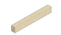
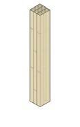
This stage involves characterizing all the timber structural elements that could be used for the timber top-up. The aim is to create a toolbox or inventory of suitable timber components that can be utilized in the following proposal stage. This includes identifying and categorizing different timber elements such as beams, columns, trusses, connectors, and panels to understand the options for selecting and integrating timber elements in the overall design.
For the definition of vertical structural components, the design principle of The open space floor plan allows for different configurations. Glulam columns are designated as horizontal elements to provide maximum flexibility in floor plan arrangement and concentrate the necessary structural area in an open grid, enabling flexibility. The elements need to be aligned with the existing walls of the structure, following a predefined grid.
For the proposal of slabs, the grid size represents a hard constraint as, for instance, for Cross-laminated timber production, the maximum width is 3.5 with a length of up to 16 m, which restricts the possibility of directly connecting the slab to the columns. Therefore, it is required to include a beam system to support it, which will
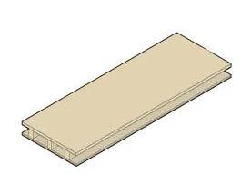
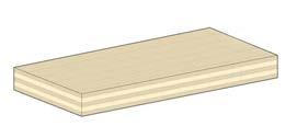
connect the columns described in the next section for the slab. Then is a proposed two-directional system that can fit in spans of 3.9 and 5.4. The proposed elements for the study are CLT. Based on the grid design, the structural components can be identified in Figure 21.
Predimension of the structural components.
In this process, the inventory of structural components proposed in the previous stage is utilized to determine the initial dimensions of the system components. The pre-dimensioning process involves evaluating the load requirements, structural performance criteria, and other relevant factors to assign appropriate dimensions to the timber components. This step helps in ensuring that the structural.
Skyciv is used to determine the minimum size based on the loads defined in Section 5.2.3 and the structural requirements stated in EC 5 for calculating beams, columns, and slabs. The results of this dimension can be seen in Chart XX.
5.2.5 Evaluate
The next stage of the process is the evaluation of different structural scenarios for the timber top-up proposed in the previous stage. Moreover, to demonstrate compliance with the limited state design values specified in the structural codes.
Parametrization of the 3d model and the creation of the different scenarios.
This process focuses on adding to the model in Section 5.1.2 the structural proposals defined in the previous section of the timber Top-ups into the digital environment. Moreover, to input into de components of Grasshopper and Rhino gathered so far in the process: Materials, preliminary dimensions, geometries, load cases, and supports. Structural evaluation of the scenarios.
By having the parametrized model in Grasshopper, Karamba 3D can evaluate the defined criteria from the previous stages and ensure that the timber top-up structure meets the required structural values. The evaluation process in Karamba 3D includes analyzing factors such as structural stability, load-bearing capacity, deflection limits, and the other relevant performance indicators previously stated in the “define” stage.
For the Study case, three scenarios are defined to be evaluated in the Evaluate stage.
• Scenario # 1 Don’t Remove: Top-up with timber without demolishing.
This first scenario aims to understand the maximum capacity to Top-up by utilizing the remaining structural capacity of the existing components in the RC structure. Top up the existing structure to increase the capacity of the building as much as structurally possible without retrofitting the existing RC structure.
• Scenario # 3 Maxima: Remove one story and add four.
The purpose of this scenario is to evaluate the possibilities of height increase after removing a fraction of the structural mass of the RC components in the structure, more specifically, a fifth of the total mass in this case.
• Scenario # 2 Minima: Remove one story and add three.
This scenario intends to analyze the results based on increasing the minimum amount of timber layers, moreover by removing one layer and adding two additional ones. This experiment Will set a minimum value of the area. The idea is to create a lower value for a numeric where the range is between minimum and maximum.
Environmental impact analysis of the scenarios with the Ansys Ecoadut tool.


The following process involves collecting data from two sources to assess the environmental impact of the timber top-up design. Moreover, the analysis focuses on analyzing the embodied carbon (measured in CO2 kg per m3)


Firstly, information about the mass and composition of the different design iterations is gathered from the "Structural evaluation of the scenarios" stage. And secondly, data related to manufacturing the structure’s components are collected from the earlier "Define" stage.

All of this information is input into the Ansys Ecoaudit tool, which facilitates the assessment of environmental performance by analyzing the embodied carbon and Upfront embodied energy of the project during its lifespan supported on databases and assumptions from academic research.
The environmental analysis carried out with the Ansys Ecoaudit will provide valuable results on the carbon footprint and energy consumption associated with the timber top-up that will be discussed in the following stage.
5.2.5 Conclude
The final stage of the framework involves comparing the structural results obtained from the evaluation stage, including the structural and environmental impact assessments, among the proposed scenarios.
In this stage, the outcomes of the different scenarios assessed throughout the methodology are analyzed and compared. Moreover, to examine the structural performance regarding stability, load-bearing capacity, deflection, and other relevant criteria of the overall structure previously established in the earlier stages.
Furthermore, the environmental impact assessment results are also evaluated among the scenarios. This includes evaluating the embodied carbon and energy values obtained from the environmental analysis stage to identify which design options have a lower carbon footprint and energy consumption, contributing to a more sustainable solution.
Finally, by comparing the scenarios' structural and environmental results, it is possible to make informed decisions to select a final design proposal that meets the required structural criteria but also demonstrates a reduced environmental impact.
The outcome of the whole framework ensures that in other processes, the Top-up timber design will align with structural integrity and sustainability objectives and therefore give insights for the decision-making about continuing with the process or considering a different approach.
For the conclusion and result part of the study case, Chapter 6 will describe them and will explain the obtained results.
a est. Praesent luctus facilisis semper. Fusce eu aliquet ligula. Donec turpis ante, aliquam in malesuada nec, tempor id enim. Phasellus porta ac ligula at suscipit.
Suspendisse eget tincidunt sapien. Ut ornare sem a consectetur aliquet. Sed mollis, nunc eu lobortis placerat, urna enim rhoncus felis, id pretium magna eros sit amet augue. Aenean risus neque, euismod in blandit ac, bibendum non augue. Sed euismod neque id sapien rutrum facilisis. Sed vel volutpat tortor. Vivamus placerat pretium semper. Phasellus rutrum orci lorem, id bibendum sapien ornare maximus.
5.2.6 Architectural design
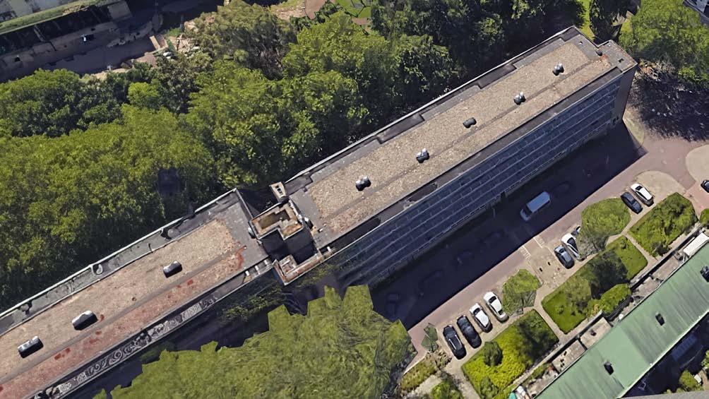
The objective outlined in Chapter 4.1.3 was the demolition of the buildings on Chopinlaan in order to replace them with single-unit houses of reduced height compared to the current Gillisbuurt buildings. This initiative was driven by the Delfts Geemente's aim to enhance transparency from Chopinlaan Street to the interior of the residential complex, which houses two parks. The intention was to improve the urban conditions in the neighborhood.
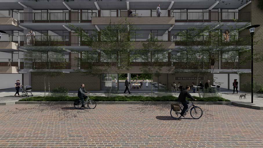
To achieve this, the ground floor is opened up to allow for transparency and improved visual conditions from Chopinlaan to the park. The relocation of ground-floor apartments to the top level frees up the ground-floor space. Stores and communal activities are added on the ground floor to diversify the building's activities and make the neighborhood more dynamic throughout the day and night.
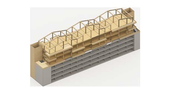
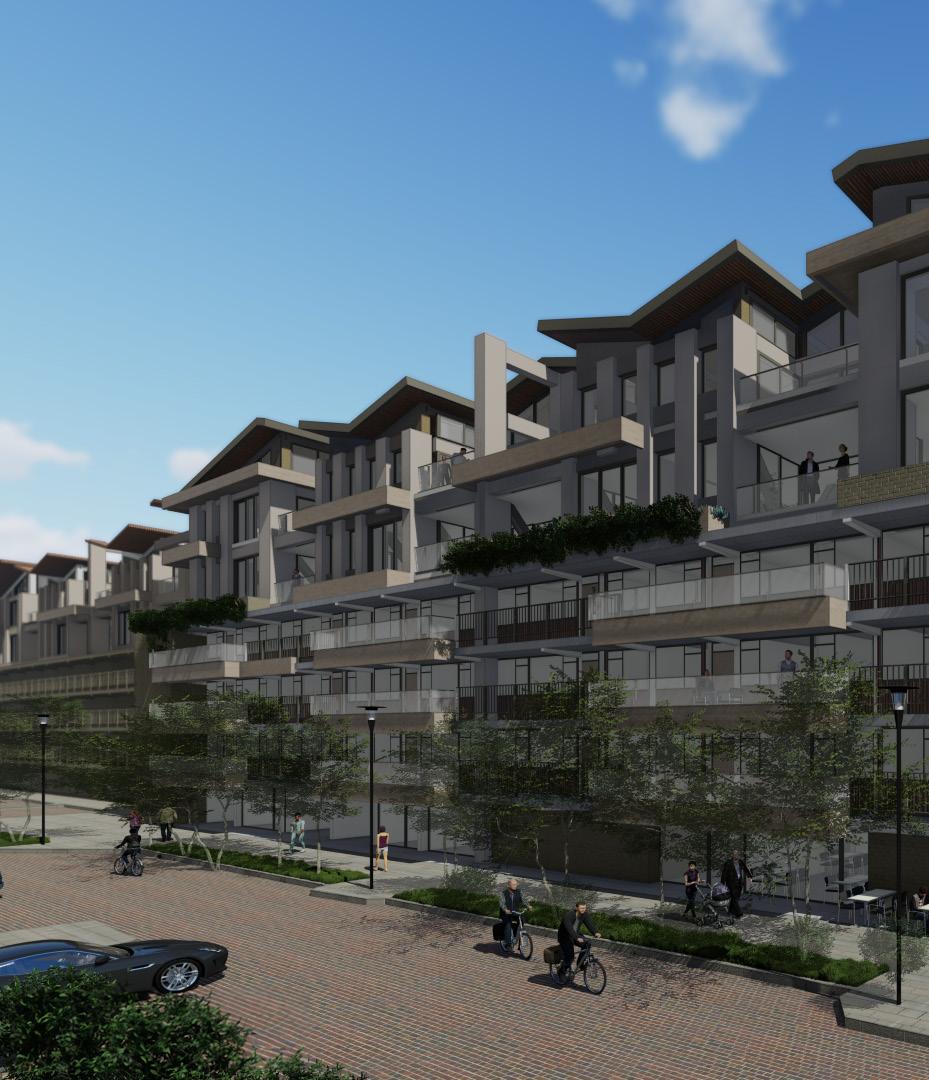
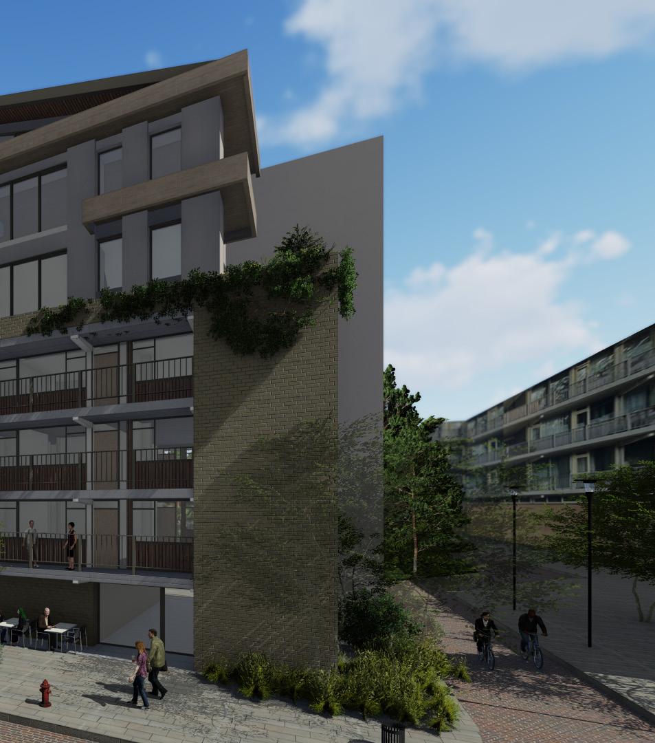
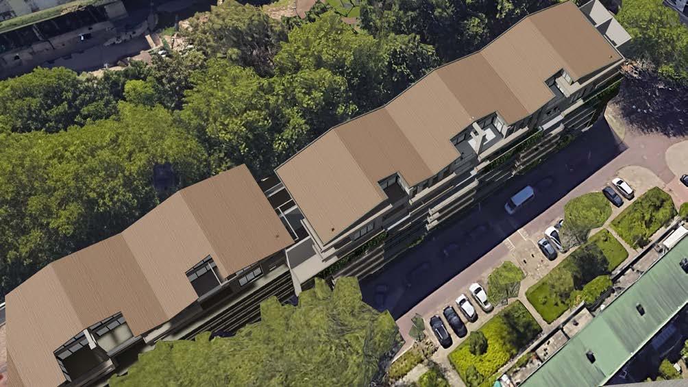
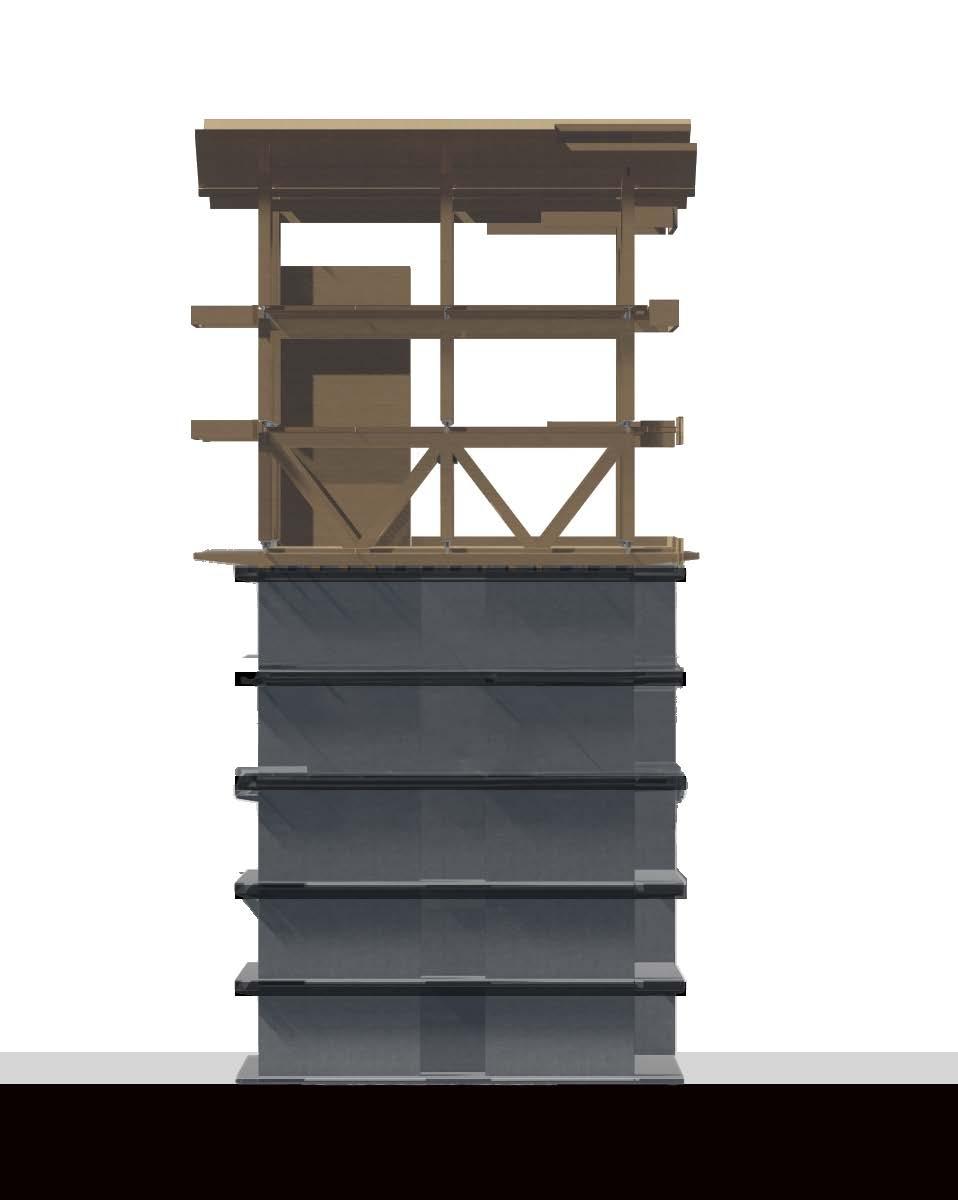
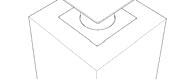
Regarding the height of the intervention, the top-up involves adding two stories of timber while maintaining the existing RC structural components as can be seen in the rendered image 8 in the next page. This decision is made to preserve the uniform building height in the surrounding area and prevent overshadowing of the buildings below. It also avoids obstructing natural light and views in the neighboring structures.
In terms of energy efficiency, the building's facade is being intervened to reduce energy demand. This includes measures such as insulation, improved air tightness, temperature-controlled heating systems, and improved ventilation.
These interventions aim to offset 72% of the building's total embodied carbon represented in the use stage of the dwellings. The remaining 38% corresponding to the upfront carbon energy, is intended to be reduced by constructing the timber top-up.
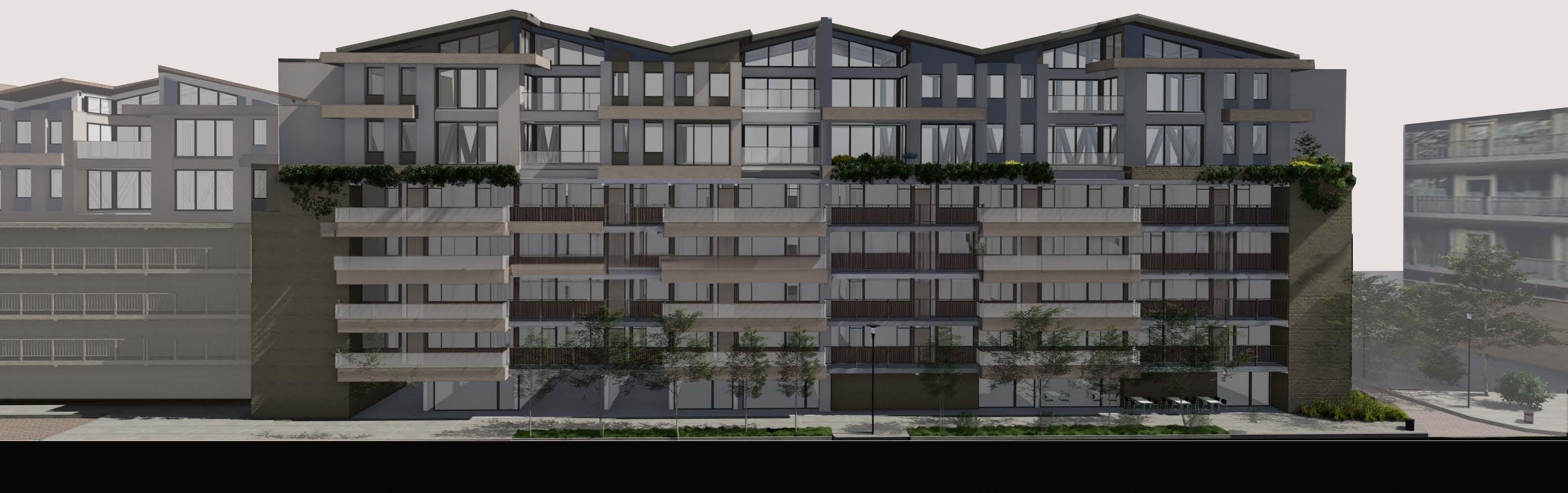
As part of the intervention, some of the existing concrete galleries are being replaced with timber slabs. This allows for the expansion of corridors in front of existing apartments and the creation of sun terraces/gathering spaces for communal interactions. It also breaks the monotony of the current gallery facades and reduces the weight of the structure. These terraces integrate the top-up design with the existing structure, creating a unified architectural typology.
Research for design
From an urban perspective, the introduction of these terraces enhances outdoor activities and improves the relationship between residents and the street environment. This contributes to an improved sense of security in the sector as can be seen in image 9.
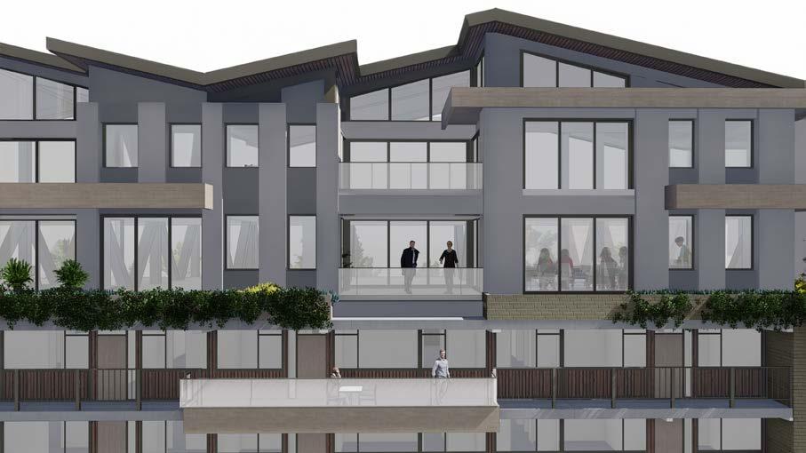
The desition of having tilted roofs was taken as it offer numerous advantages for the Netherlands.Having a high rainfall, the sloped roofs enables efficient rainwater drainage, minimizing water damage in the interior. Additionally, during snowy periods, tilted roofs prevent snow accumulation, reducing this load in the loadcase. Moreover, these roofs also facilitate the installation of solar panels at optimal angles, maximizing energy generatio. Furthermore, from an architectural perspective the angled roofs allow for better natural lighting, reducing the use of artificial light in the interior. Lastly, tilted roofs adds and architectural interest to the the urban landscape where flat roofs are predominant.
Grid and structure
Suspendisse eget tincidunt sapien. Ut ornare sem a consectetur aliquet. Sed Section 5.2.4 emphasizes that the top-up grid's definition relies on the existing grid of the building's RC structure. To align with the concrete walls of the existing structure, a proposed grid measuring 3.9 meters and 5.4 meters by 10.8 meters is suggested, as depicted in image 11. This grid arrangement serves to organize the placement of glulam columns responsible for transferring loads to the unidirectional CLT slabs.
Furthermore, there is a proposal to extend the CLT slabs to create balconies on the northern and southern sides. These extended slabs would be supported by the CLT stabilization cores, enabling the structural system to gain rigidity and withstand wind loads effectively.
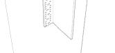
Additionally, a bracing system composed of glulam beams is recommended for the transition floor between the top-up and the existing RC structure. This bracing system aims to distribute loads evenly between the top-up and the existing concrete walls. Its purpose is to ensure structural integrity and alleviate concentrated loads on top of the RC walls.
Architectural program
The structural disposition of columns in the proposed floor plan configurations prioritizes flexibility, aiming to create an open floor plan that allows for adaptable space utilization. Unlike the existing RC structure, the top-up design's absence of fixed structural walls facilitates easy reconfiguration and layout adjustments according to changing needs over time. This flexibility allows the building to accommodate diverse uses and ensures that the lifespan of the building is extended.
Considering the predominant use in the Gillisbuurt neighborhood is currently housing, the intervention proposes a mixed-use approach with commercial spaces on the ground floor. However, considering the potential future shifts in urban dynamics, it is important to design the building to accommodate different housing typologies, as can be seen in image 15. This circular approach ensures the building's ability to adapt to changing demands and extend its lifespan.
Furthermore, the proposed structural design allows for potential future uses beyond housing. It could be repurposed to serve as student housing, a hotel, or even retrofitted to comply with codes and accommodate office spaces in the future. This versatility in potential uses enhances the building's adaptability and ensures its relevance to evolve and respond to the changing market demands.
Circulations
The top-up design proposes two types of circulations for efficient movement within the building. Firstly, there is the vertical circulation, which includes the elevator shaft, ducts, and staircase. These elements are located within the stabilization timber core, as illustrated in image 16. This vertical circulation system allows easy access to both the existing building and also the top-up. Moreover, The proposed circulations also serve to comply with fire safety requirements, which mandate the placement of staircases accessible to evacuate the building in 120 minutes.
In terms of horizontal circulation, two options are presented. The first option suggests a central circulation route that provides lateral access to households and rooms. This option allows for a seamless flow between different areas on each floor. The second option is to maintain the existing circulation pattern of the building, utilizing side corridors similar to the current layout. This choice would maintain familiarity and continuity for occupants.
TUDelft-BK| 2023
By incorporating these different types of circulations, the design caters to various functions and requirements over time. It offers flexibility and adaptability as the building's needs may change.
Connections and assembly
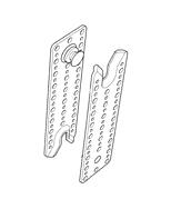
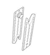
For the connections of the structure, is opted for steel connections as seen in Table 7. Since timber construction has been popular in recent years, there has been an increase in systems capable of responding to highrise situations. The reasons behind using steel respond to the benefits that they present in the present as follows:
From a structural perspective, allow:
• A higher structural strength compared to others: As they provide robustness and strength to the timber structure, allowing it to withstand the vertical and lateral loads experienced in high-rise buildings. The steel connections enhance the overall structural integrity and ensure the stability of the timber system.
• Durability: Steel connections provide durability and longevity to high-rise timber structures, ensuring the long-term performance and reliability of the connections..
From a circular perspective:
Reversibility and Reusability: Steel connectors allow for the disassembly of timber elements without causing damage, providing a reversible construction approach. The ability to disconnect and reuse timber members facilitates the Reuse, Refurbish, and Repair of timber components in the structure.
EoL sorting: Steel connectors facilitate the separation of timber and steel components during the disassembly process at its EoL. This segregation makes the sorting of materials efficient for recycling or proper disposal, contributing to waste reduction and improved environmental outcomes.
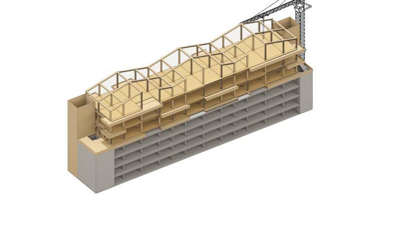
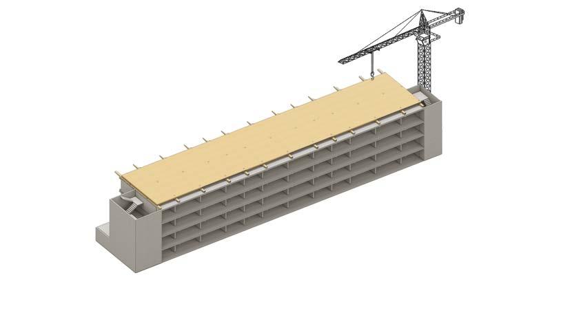
The construction process of a timber structure in a top-up offers the benefit of
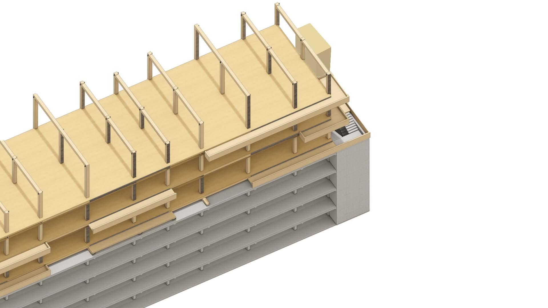
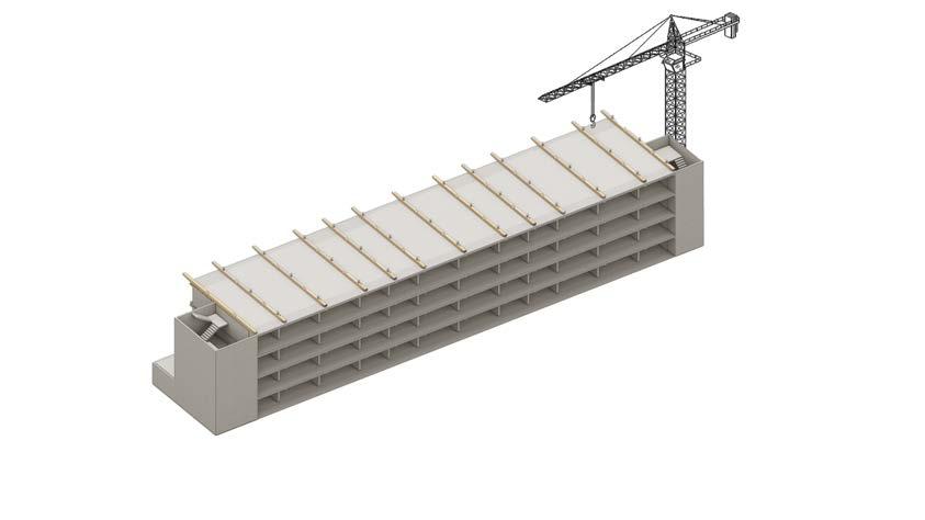
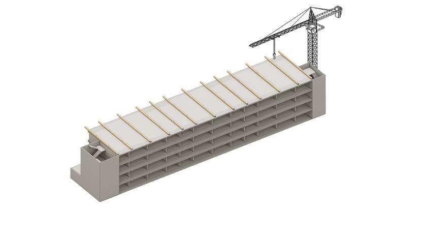
being performed without interfering with the use stage of the existing structure. This means that the construction works can take place while the building below remains operational and occupied. Moreover, the process can be resumed once the final drawings are finished, as seen in Image 17 in the following steps:
Site Preparation: (step a): Consist of installing a crane next to the existing building that will lift to the top of the building all of the prefab components.
Timber Fabrication: The timber components, such as glulam beams, columns, and CLT panels, are fabricated off-site. The timber is precisely cut and shaped according to the design specifications, ensuring accurate dimensions and connections. Moreover, Steel connectors, such as plates, brackets, and fasteners, are positioned and installed in the timber components.
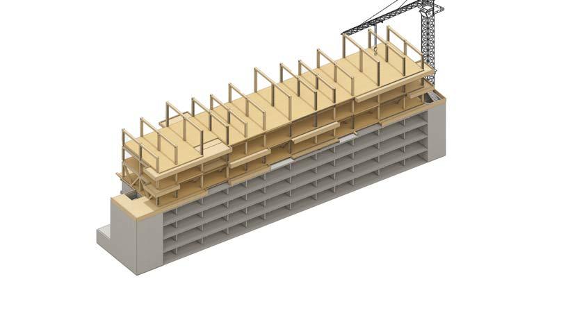
Assembly and Erection (steps b to g): The prefabricated timber components are transported to the construction site and lifted into place using cranes or other lifting equipment. The components are carefully positioned and connected according to the construction drawings. This includes aligning and bolting the steel connectors to ensure secure and rigid connections.
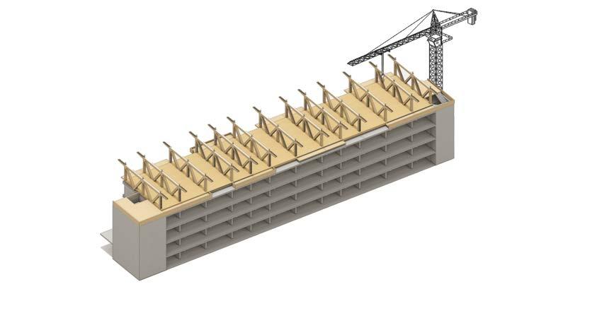
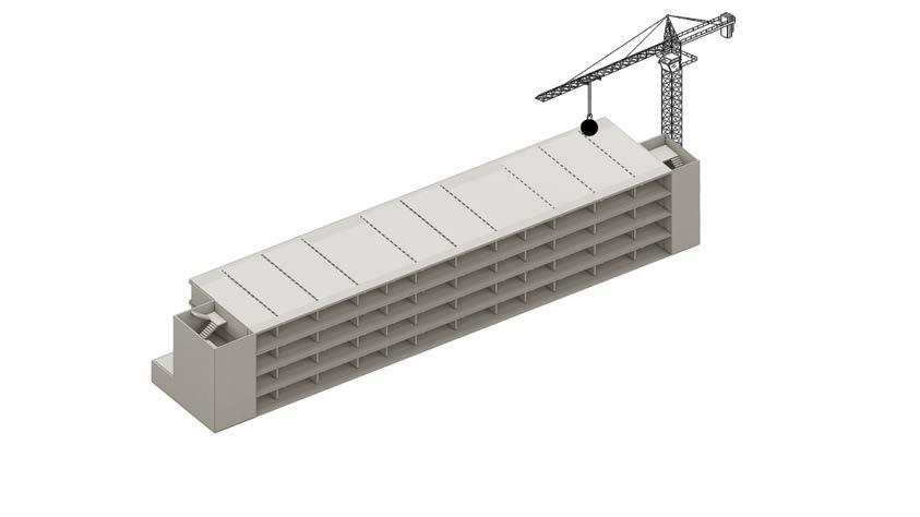
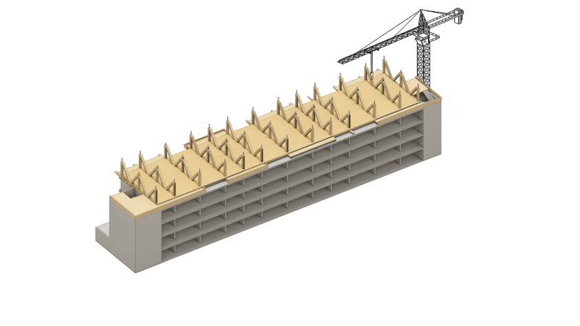
Installation of Stabilization Cores and roofs (step h): Stabilization cores, typically made of timber, are incorporated into the structure to enhance stability and resist lateral forces. Once the main structure is in place, the construction of floors and roofs commences. The roof made of CLT panels is assembled to create a weather-tight and durable covering.
Finishing and Services Installation: Interior finishes, such as wall cladding, ceilings, and flooring, are installed. Electrical, plumbing, and heating.
Table
åå ÉÅíáçåK`~êÄçå=ëí ÉÉä=éä~íÉ
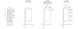
`çåÅÉä~ÉÇ=Åç åå ÉÅíçêë=Ñçê=ÜáÖÜ Å~é~Åáíó=ëí~åÇ~êÇ=Åç åå ÉÅíáçåë
åå
s
å~áäë NQSIS=âk RothoblasConcealled


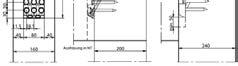
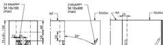
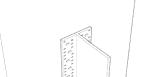
steel column conectors in the transition floor. d. Instalation of Ribbed box slab in the trasnsition floor. e.Instalation of transition trusses. f. Instalation of beams,
For the experiment setup, the defined scenarios are analyzed based on the following criteria; they will be explained in the further section based on the software used to perform the simulations:
Rhino 7 + Grashopper +Karamba 3d to analize:
Reaction in the foundations after Toping-up.
• Utilization of the Timber top-up components (maximum shear and moment).
• SLS - Deflection limit (Nodal displacements).
Reactions of the concrete structure (Nodal displacements).
• Utilization in the concrete structure.
Rhino 7 + Grasshopper + Granta Edupack + Ansys Ecoaudit Tool to analyze:
• Upfront embodied carbon.
6.1 Experiment Set-up
Scenarios set-up: RC elements remove, timber added, mass and volume
Input values to be used in the software Granta Edupack to calculate the upfront carbon emissons of the stucture.
Existing building area Area of one layer of a existing Area of one layer of a Top-Up
Exixting volume of concrete in the existing building
Existing mass concrete in the existing building
Existing mass timber in one layer
Existing volume of concrete in one layer density of scpurce C24 ratio of molecular weight Co2
Moisture of timber
Secuestred carbon of Spruce C24
Dissasembly potential of with concrete building
Dissasembly potential of timber top up building
Experiment 06
Definition of disassembly potential for the reuse of RC components in the existing structure and for the timber components in the top-up
Concrete building (5 stories) recycle Table 12 Calculation for the disassembly potential of the components in the project based on the
POTENTIAL MEASUREMENT METHOD VERSION 2.0.
Definition of the sequestration carbon of Spruce C 24 Timber 12% humid content used in the timber top up components.
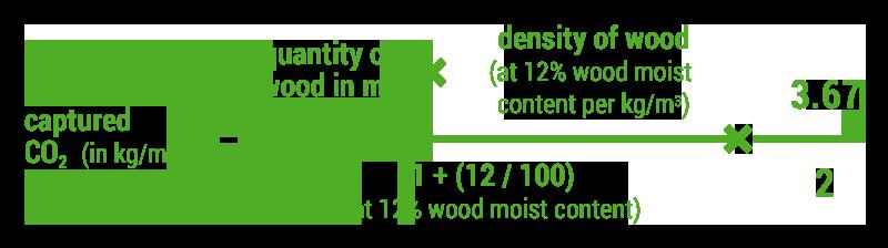
Figure 36 Equation to estimate carbon sequestration of wood. As seen in Section 3.1.2, woods have the potential to sequestrate carbon; based on (Lugt & Harsta 2020), the carbon sequestration of C24 timber is calculated.
6.2 Results
6.2.1 Reaction in foundations after Toping Up.
FIgure 37. Reactions in the foundations after toping up
TUDelft-BK| 2023
Figure 37 illustrates the reactions in the structure’s supports (measured in kN in the Y axis) compared to the analyzed scenarios in the X axis. Consequently, these reactions will be the forces that will be transferred into the existing foundations of the building in each scenario.
Scenario 0: Existing building (Sc. 1) shows the current reactions in the supports today without any intervention, where each point corresponds to support in the structure's base.
When comparing Sc.0 with the following four scenarios, the following conclusions can be drawn:
Scenarios 1 to 3 progressively increase when more Timber Top-up layers are added. Among these three, Scenario 3: Maxima (Sc.3) demonstrates the highest reaction increase, reaching approximately 400 kN in each support. Scenario 4:Variation (Sc.4) shows a similar but lower result than Sc. 3.
Scenario 2:Minima (Sc.2) and Scenario 1: Not remove (Sc.1) exhibit a comparable load increase in the supports of approximately 200 kN compared to Sc.0.
Furthermore, the hypothesis stated in Section 1.3 at the beginning of the document, suggesting that replacing RC components with timber could lighten the structure, is partially validated. Although timber is lighter than RC, replacing RC components with timber components (as tested in Sc. 2, 3 & 4) does not necessarily reduce the reactions in the existing building foundations.
One possible xplanation for these results is that while the weight of the removed RC components might be replaced with a similar one of timber (representing more mass and hence more area), there is an increase in the load cases due to the expanded area of the building, which include new wind and live loads. This hypothesis will be further investigated for the final report of the graduation project in P5, considering its implications in the design process.
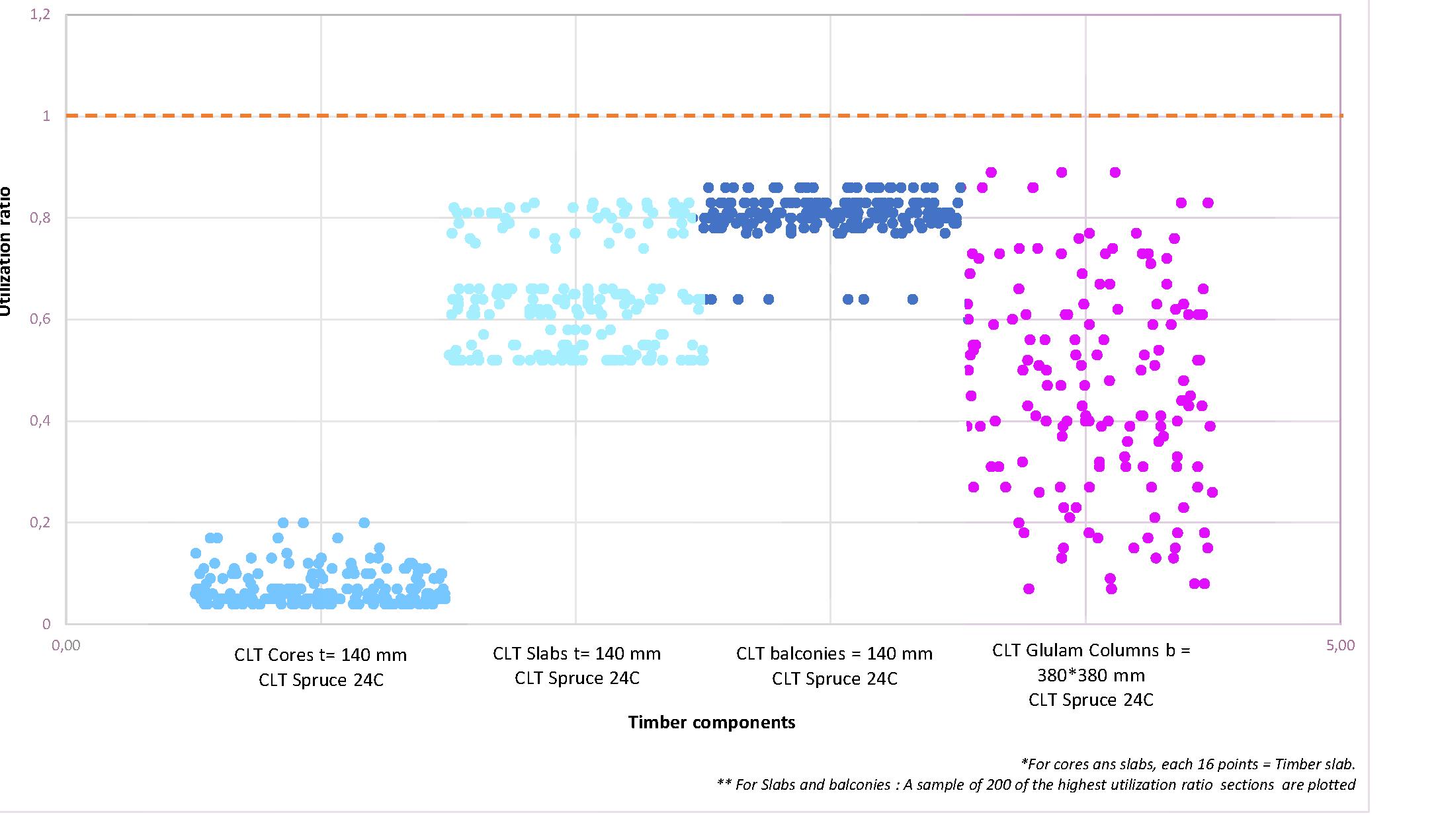
6.2.2 ULS - Utilization of the Timber components used in the top-up (maximum shear and moment).
Figure 38 illustrates the utilization ratios of various timber components within the timber top-up in Scenario 3.
On the Y-axis, the utilization ratio (the applied load divided by the design capacity of the component) is shown, while the X-axis represents the evaluated components.
Consequently, four timber components were plotted from the model: CLT cores, CLT slabs, CLT balcony slabs, and CLT glulam columns. Plotting the following results:

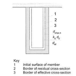
The 140mm thick CLT cores exhibit an 80% excess capacity. This excess may be attributed to two factors, which will be further analyzed in the P5 report: The cores solely transfer tension loads resulting from wind loads on the slabs, and the charring layer tends to increase the dimension of the element.
The CLT slabs show a utilization ranging between 50% and 80% depending on the specific structural situation, such as the 3.9 or 5.4 meters span. The remaining excess capacity is due to the over-dimensioning of the section caused by the charring layer.
The utilization of CLT balconies ranges from 78% to 85%—the excess utilization results from the over-dimensioning of the section due to the charring layer.
For the glulam columns, it is evident that some columns have higher utilization than others. This discrepancy arises because all columns currently have the same dimensions in their section, which means that those on the lower levels of the Topup experience higher load cases compared to those on the upper levels, such as the ones on the last floor, which only bear the loads from the roof.
All components are below the limits, meaning that ULS (bending, normal, and shear) can bear and transfer the proposed load case. A further process will focus on optimizing their section to reduce the mass of timber of the Top-up.
6.2.3
Figure 39 compares the displacement of nodes in the CLT roof slab in Scenario 3 under two strategies: utilizing stabilization cores and not using them at all. The Y-axis represents the numerical values of node displacement caused by wind loads. The maximum deflection limit for the overall structure, as defined by EC 0, is stated as max. deflection = H/500 (0.046 meters = 23.22 meters/500).
SLS - Deflection limit (Nodal displacements).06
The chart demonstrates that if the structure consists solely of beams, columns, and slabs, the roof will experience a displacement of over 6 centimeters due to structural instability, surpassing the acceptable values. However, in the following scenario, it can be observed that with the inclusion of stabilization cores, the displacement values can be significantly reduced to values that fall within acceptable limits.
Stabilization cores represent one potential strategy to address excessive deflection in the CLT roof slab. However, it is important to note that they are not the only solution available. In the next stage, other optimization processes will be employed to explore alternative approaches, such as introducing bracing components to reduce the mass of timber within the cores.
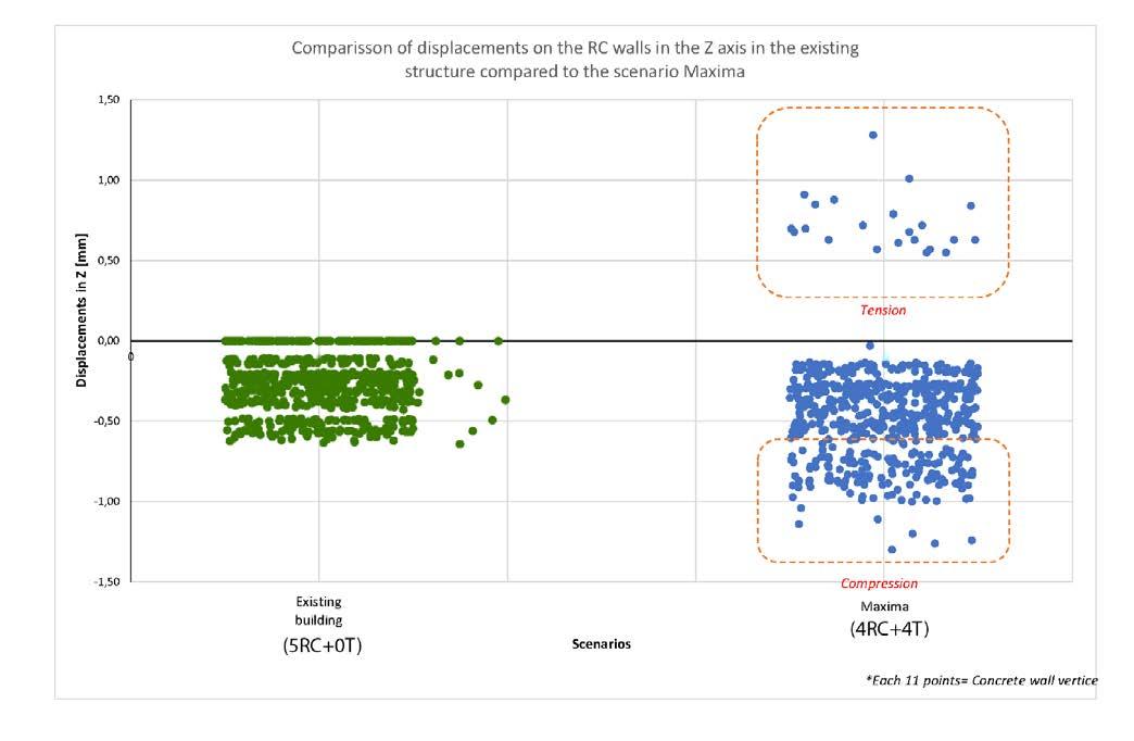
6.2.5 Reactions of the RC walls in the top-up connection (Nodal displacements).
FIgure 40. Reactions of the concrete structure (Nodal displacements).
The following results aim to assess the impact of the top-up on the existing concrete walls in terms of vertical displacements, as previously stated in the purpose stage as one of the structural assumptions.
The graph illustrates the displacements in the Z-axis of the concrete walls located in the first four stories of the existing structure. To the left, It can be observed that the existing structure today experiences a maximum displacement in the Z axis of only half a millimeter due to the current load case scenario, which can be considered negligible.
6.2.6 ULS - Utilization of the RC walls in the structure after Toping-up.
The purpose of thye analizis iun figure 41 is to evaluate the structural capacity of the existing RC walls in terms of the Utilization ratio when subjected to different timber top-up scenarios. The focus on evaluating the walls is because they are the primary components responsible for transferring and supporting loads of the top-up.
In Scenario 0, it is evident that the existing structure has an overcapacity of 80%, indicating the presence of unused potential capacity that could accommodate additional weight.
81
1 -0,397770,600,22
10,0389291,040,22
1 -0,377950,620,22
1 -0 329980,670,22
10,4132211,410,22
10,1479951,150,22
10,1752981,180,22
1 -0,393460,610,22 10,0118321,010,22 10,1918281,190,22 10,1196681,120,22 10,0867911,090,22
1 -0 091990,910,22
10,3534571,350,22
10,2431431,240,22
10,4739331,470,22
10,4529551,450,22
1 -0 397850,600,22
1 -0,375540,620,23
10,0981341,100,23
1 -0 295810,700,23
10,1195141,120,23
1 -0 187850,810,23
10,0457051,050,23
1 -0 284090,720,23
1 -0,268720,730,23
DON’T REMOVE 2 -0 181331,820,23
20,2262222,230,23
2 -0,283631,720,23
20,0038032,000,23 2
Scenarios 2 and 4 demonstrate a 30% increase in loads due to the added weight compared to Scenario 0. Despite this increase, a remaining capacity of 50% can potentially be utilized to accommodate an overload.
The most demanding scenario, Scenario 3, exhibits an overcapacity of 40%, indicating that it can withstand even higher loads without exceeding the utilization limit.
6.2.7 Upfront carbon
A roadmap was created to determine the top-up intervention's upfront energy, illustrating 18combinations of End-of-Life (EoL) scenarios for the structure's first and second cycles.
The project has generated 2454 tons of CO2 emissions after analyzing the extraction, manufacturing, and transportation processes since its construction in 1968. Without any interventions, this emission level will remain unchanged until a decision is made.
After comparing the previous iterations, the following conclusions can be drawn:
Reusing materials in the first and second cycles is the most effective strategy for reducing CO2 emissions across all scenarios.
Downcycling and recycling reinforced concrete (RC) components in the first cycle, followed by energy recovery of the timber in the second cycle, resulting in the highest overall CO2 emissions. This strategy emits even more CO2 than leaving the structure untouched without interventions.
Downcycling and recycling RC components in the first cycle, followed by reusing the timber, reduce CO2 emissions compared to leaving the structure without any interventions. However, this difference is more noticeable when the entire structure is dismantled and replaced with a new timber structure.
Combustion
Total Upfront C second cycle timber
a Dissasembly potentia * Includes a Dissasembly potential of building of 1.00
-4,32E+056,64E+051,91E+054,23E+056,37E+044,32E+059,04E+04-6,64E+05919-1502 -7,67E+058,85E+052,55E+053,72E+058,50E+047,67E+051,21E+05-8,85E+051225-3923 otentiaIncludes a Dissasembly potential of building of 1.00
Stages in the life
7.1 Discussion
The findings of this study provide information on the possibility of using timber topups in existing reinforced concrete structures to increase the building's area capacity. By analyzing different scenarios. Moreover, regarding the research question:
How can the area capacity of existing Reinforced Concrete structures be increased and extend their lifespan by using timber top-ups?
The document states that the area of the structure might be increased by having two approaches:
On the one hand, by constructing the top-up on the existing RC structure as seen in scenario 1 (5RC+1T), and on the other by deconstructing part of the components to reduce the weight of the structure as seen in scenarios 2 (4RC+3T) and 3 (4RC+4T).
In both approaches, the results seen in Figure 41 (RC wall utilization) show an opportunity in the case study’s structure, represented by the excess capacity in the RC walls. This capacity can load them until their utilization limits, allowing components to withstand even the highest scenario.
Regarding reactions in the foundation system, The results exposed in Figure 37 shows that although the deconstruction of one layer of RC components might reduce the structure's weight in scenario 2 when topping up, these reactions increase, overpassing the values of the original structure.
However, if we compared scenarios 1 & 2 (W & 4RC+3T) can be concluded that removing one layer of RC components and adding three of timber will have a similar increase in the reactions in the foundations as not deconstructing and adding one layout, which means that deconstructing would allow more capacity with a similar load increase. In the case of scenario 3 (4RC+4T), there will be an exponential increase in the foundation system.
Therefore, it is essential to evaluate the structural capacity of the foundation system to withstand the new load-case scenarios derived from topping up, even if there might be an opportunity to use the excess capacity in the utilization of existing RC components.
However, having the base of the parametric model, it would be relevant for further research to explore different deconstruction/adding situations that would overload
the existing foundations to limit the size of their intervention. For example, analyzing a scenario where two layers of concrete and four of timber are added (3RC+4T):
To approach the subquestion: How to make visible topping up in the decisionmaking for stakeholders when facing demolishing/building new?
The step-by-step exposed in the exploration framework proposed in Chapter 5 was intended to document the design process of the timber top-up for the study case. Therefore approaching top-ups from an architectural domain contributes to visible this strategy as an alternative to demolishing.
To approach the subquestion: To what extent can the capacity of an existing RC building with timber be increased by reducing the weight of the RC structure? The research shows that it can be increased as much as possible considering the following criteria:
The height of the building is determined by the capacity of the existing structure and its main structural components to withstand the new load case scenarios. As seen in Figure 41 with scenario 3 (4RC+4T), it’s even possible to double the height of the building. However, since the research focused mainly on analyzing the components' utilization and the system's load-bearing capacity, further research must analyze other relevant structural requirements, such as connections to the existing building and foundations’ capacity to withstand and transfer loads, that would determine structural feasibility.
However, as illustrated in the research, the top-up's area capacity must also be analyzed from other relevant domains of knowledge that might determine the total height. In the case study, doubling the height of the existing building with a topup represents a massive aesthetical result that affects the building’s aesthetics. Therefore in this particular case, as seen in the proposal section, it opted to increase the height of two stories.
Which structural timber systems can be more effective when topping up existing Reinforced Concrete Structure (RCS) buildings?
As seen in the case study proposal, some structural products might be more suitable to comply with the local fire safety regulations due to the mass required to generate the charging layer during a fire. CLT and Glulam being mass timber components might work to increase the height of the building considerably. Furthermore, these two products can perform better in terms of overall structural stability necessary to withstand the wind force in the new load case scenario. Therefore are recommended in cases where the top-up overpass the fire safety height and is subjected to higher wind loads. Moreover, a system based on timber columns and beams proved effective as it confers the top-up possibility to house different plan layouts during its lifespan.
Also, components that would rigidize the system are mandatory to create structural stability in the top-up, as seen in Figure 39, where it was demonstrated that not having CLT cores would surpass the allowable deflection limit of the building with the top-up.
On the other hand, the research also focused on limiting the amount of timber entering the chain as much as possible. Therefore although the pre-dimension of the components was proposed with the principle of using as less as possible necessary to comply with the safety factors, there are still opportunities to reduce the volume used in the intervention by following strategies such as:
Reducing the section of timber Glulam columns in the upper levels: They are not required to withstand and transfer as many loads as the ones in the bottom used for the dimension.
Replacing the CLT cores for stabilization of the structure with another system: Although CLT cores were used to house the elevators, shafts, and staircases, by using
other stabilization systems in the structure, such as bracings, it might be possible to rigidize the Structure with less use of timber.
What opportunities and limitations have topping up an existing RC structure building?
Opportunities
From an environmental impact perspective, as seen in Figure 45, due to the capacity of timber to sequester carbon, adding mass to increase the capacity would reduce the upfront energy of the building considerably in all the scenarios. However, as seen in scenarios 1 & 2, adding a small timber volume might not reduce the upfront carbon enough to compensate for the emissions produced in constructing the structure.
However, Scenario 3 (4RC+4T) proves that adding more volume to the intervention by increasing the height would lead to higher carbon sequestration than the other two scenarios, which means even a reduction of almost half of the upfront carbon produced in 1968.
Moreover, it is relevant to consider that the upfront carbon emissions of the structure represent just a percentage of the overall CO2 emissions of the building. As mentioned by Moazzen & Ashrafian (2022), 72% of the embodied carbon of the building Life cycle is attributed to the building's use stage, while upfront energy represents 28%. Therefore, to effectively recover part of the CO2 emissions of the whole building, topping up should not only be an intervention limited to increasing the capacity of the building but also should aim to incorporate interventions that may reduce CO2 emissions in operational use.
On the other hand, it is relevant to consider that In all the scenarios, if this sequestered CO2 of timber is released into the environment at the EoL when burning for energy recovery, it would increase the upfront emissions of the whole structure. Therefore, prolonging the life cycle of the timber structure as much as possible will be an effective strategy to reduce the overall upfront carbon emissions, as can be seen in Scenario 3 when reusing all of the components. Furthermore, it is relevant to apply in the construction sector practices that would ensure the reuse of the structure and/or its components as much as possible.
Limitations
Due to the relative novelty of using mass timber in buildings, there is considerable uncertainty regarding the fate of timber components at the end of their life cycle, whether they will be recycled, landfilled, or incinerated.
Moreover, regarding reuse as a strategy, timber being an organic material, ensuring its durabillity and long-term steady performance of its mechanical properties through its life cycle might be challenging as it is susceptible to be deteriorated by external conditions such as biological agents, moisture differences, temperature differences or deformation due sagging.
In the case of concrete, RC structures can face several common problems throughout
their life cycle, including Corrosion, cracking, and degradation, which might affect the possibility of being reused.
The potential disassembly factor Van Vliet et al. (2021) proposed for estimating the disassembly potential of RC and timber components needs to consider the structural components' physical integration when disassembling. Therefore, cascading both timber and concrete in multiple cycles might have limitations. Therefore, to reuse them, evaluating their physical integrity is relevant to determining whether they are between admissible utilization values.
In conclusion, this research thesis aimed to analyze the structural feasibility of building timber top-ups in existing reinforced concrete structures to increase the building's area capacity.
The findings demonstrated that although there might be different approaches to constructing them, there are opportunities to utilize the excess capacity of RC walls by increasing height using lightweight material, This research corresponds just to a small piece of findings in what might be a strategy that should be analyzed from different perspectives to make it a massive construction system.
7.2 Reflection.
The graduation project: “Timber Top-ups for existing reinforced concrete structure Buildings” is part of the “Structural Design for Change” graduation studio of the “Building Technology master track” in the Msc in Architecture at TUDelft. This graduation studio is relevant to the construction industry’s transition from a linear to a circular economy. Because by analyzing and optimizing the lifespan of existing and new structural systems and components, it is possible to limit negative environmental impacts by managing natural resources efficiently. Overall, the studio is relevant as research about one of the building's most complex and intensive systems (materialwise speaking): the structure.
My interest in the topic started after observing that demolishing existing Reinforced Concrete structures to construct new buildings with a higher capacity was the most common practice to respond to the increasing demand for new houses worldwide. This prompts a sustainability discussion as, in several cases, these demolished building structures are still in their service life phase, producing a large amount of waste. Moreover, although significant literature has focused on studying Reinforced Concrete recycling and reuse, it still needs to improve its practice.
Therefore, this project aims to analyze the strategy of adding a substructure made of mass timber components to increase an existing RC structure building area when it reaches its End of Life. Moreover, the research proposes an alternative approach to demolishing and building a new building. Thus, the transformation of the existing building using design principles by reusing as much as possible the existing structure system, increasing the building’s area and extending its life span.
Therefore the research question for the project was proposed:
How to increase the capacity of existing Reinforce Concrete structures and extend their lifespan by using timber top-ups?
After researching the state of the art of timber top-ups, in P2, I found that there needs to be a methodology to develop Timber Top-ups on RC structures. This leads to projects of this kind, but everyone is singular and unique depending on the specific context where applied. Therefore I found it imperative not only to design the system itself but to create a framework that would allow to document the process and feed it to structure it and make a mechanism in the decision-making for future interested stakeholders.
This finding represented a considerable income in my process because I managed to redefine my sub-questions more to include in my outcomes the structure that would allow me to document and follow the design of a timber Top up. Therefore,
the product of the project became two: The proposal of a design framework for the decision-making of timber Top-ups in existing RC structures and
• The conceptual structural design of a Top-up for a specific case study. Moreover, the Subquestions that would help to approach the research question became four:
Which structural timber systems can be more effective when topping up existing Reinforced Concrete Structure (RCS) buildings? (literature review: Section 3: Timber: As a material to create top-up structures.).
• What opportunities and limitations have topping up an existing RC structure building compared to demolishing and constructing a new one? (Section 2: Topping Up existing buildings & Section 5: Research through Design).
• How to make visible topping up in the decision-making for stakeholders when facing demolishing/building new? (Section 5.1: Research through Design).
• To what extent can the capacity of an existing RC building with timber be increased by reducing the weight of the RC structure? (Section 5.2: Research through Design).
The methodology was structured as follows:
• Introduction (including the background) as a starting point for the research.
• Construction of a theoretical framework based on a literature review. Selection of a case study for top-up implementation.
• research design, focusing on developing both products while applying circular design principles to structures.
• Experimentation to evaluate quantitative criteria for the structural conceptual design, leading to results for analysis and discussion.
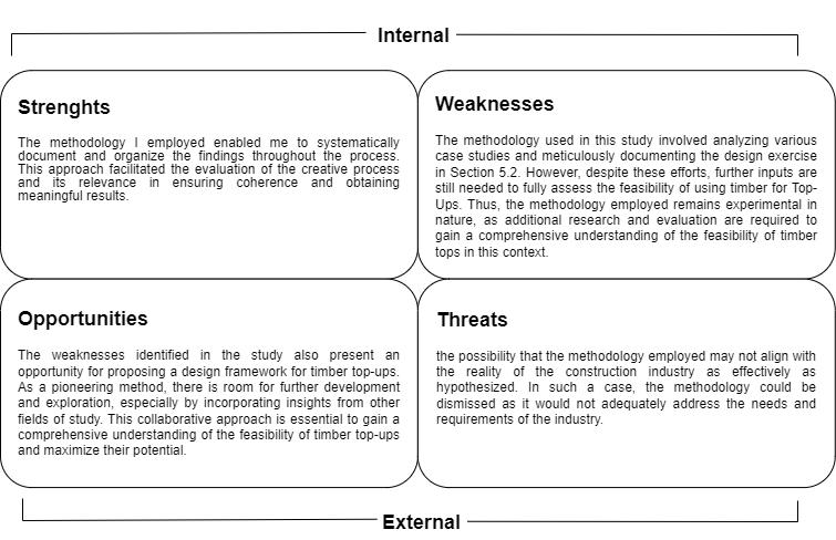
The process structure followed two principles: applying the scientific method to the research and intuitively approaching the problem from different angles through trial and error. It involved perspectives from both an architect and a building technologist. Moreover, The feedback and inputs from my mentors, who had backgrounds in sustainability, and focused on circular design and structural design, played an immense role in shaping the process and its sequence to obtain a reliable result. If the
methodology used for the project is analyzed with a SWOT analysis, the following findings emerge:
The project's contribution to sustainable development can be seen in the results achieved, where it analyzed the performance in terms of CO2 emissions for Timber Top-ups as an alternative to demolishing and rebuilding. Additionally, it explored the concept of Reuse as another viable option for renovating existing buildings constructed with RC structures in transforming an existing building using circular principles, emphasizing the importance of sustainability and resource efficiency.
Regarding the project's sociocultural impact, it responds to this aspect by offering the residents of the intervened building an alternative to reconfigure their current living conditions by expanding the capacity of their existing buildings. By doing so, they can gain additional space and explore different possibilities for rearrangement. Furthermore, these newly acquired areas can be utilized for various purposes that promote social welfare and cultural exchanges within the local communities. Thus, the project aims to provide a financial advantage by facilitating renovation works that can enhance the housing units' energy performance and indoor comfort. By aligning with the principles of sustainable development, the project seeks to improve both the living conditions and overall sustainability of the housing units.
When considering the applicability of using timber tops to top up existing reinforced structures, a practical approach is essential rather than relying solely on scientific analysis. Practical considerations are significant because they consider real-world scenarios that can directly impact the feasibility of using timber tops. Therefore, observing the practical application of timber tops in real-life situations becomes necessary to determine how effectively they can be implemented in different contexts.
In the context of assessing the extent to which the projected innovation has been achieved, it is essential to consider the following aspects of the project:
Firstly, within the Professional framework, the project aims to raise awareness of Topping Up among stakeholders in the architecture and construction field. This involves making the concept visible and understood by these stakeholders, allowing them to recognize its value and potential benefits.
Secondly, the project introduces a Design framework that provides a valuable tool for decision-making in renovation projects. This tool offers guidance and assistance in evaluating the feasibility and effectiveness of Topping Up as a viable option.
Finally, from a scientific standpoint, the project's significance lies in its practical component. The experimental method analyzes specific criteria to assess Topups’ structural and environmental performance. This rigorous evaluation helps to determine the project's efficacy and contributes to the overall understanding of its potential advantages and limitations.
Allwood, J. M. (2014). Squaring the Circular Economy: The Role of Recycling within a Hierarchy of Material Management Strategies. In Handbook of recycling: State-of-the-art for practitioners, analysts, and scientists (pp. 445–477). Elsevier.
Badraddin, A. K., Rahman, R. A., Almutairi, S., & Esa, M. (2021a). Main Challenges to Concrete Recycling in Practice. Sustainability, 13(19), 11077. https://doi.org/10.3390/su131911077
Badraddin, A. K., Rahman, R. A., Almutairi, S., & Esa, M. (2021b). Main Challenges to Concrete Recycling in Practice. Sustainability, 13(19), 11077. https://doi.org/10.3390/su131911077
Bernard Colenbrander, H. S. (2020). Heritage attributes of post-war housing in Amsterdam. Frontiers of Architectural Research, 9(1), 1–19.
Bouwbesluit 2012. https://rijksoverheid.bouwbesluit.com/inhoud/docs/wet/bb2012
Brandner, R., & Bauer, H. (2016, March). Introduction to CLT, product Properties, Strenght Classes. Cross Laminated Timber - a competitive wood product for visionary and fire safe buildings: Joint Conference of COST Actions FP1402 and FP1404, Stockholm, Sweden.
Brito, J. de, & Saikia, N. (2013). Recycled aggregate in concrete: Use of industrial, construction and demolition waste. Springer.
Carle, J., & Holmgren, L. (2009). Wood from planted forests: Global outlook to 2030. In Planted forests: Uses, impacts and sustainability (pp. 47–59). CABI Wallingford UK.
Chapman, John. (2004). Developments in utilising round timbers as structural elements. The 38th International Conference of Architectural Science Association ANZA ScA.
Chilton, J., & Mungan, İ. (Eds.). (2009). Timber structures from antiquity to the present: Proceeedings of the international symposium on timber structures, 25-27 June 2009, Istanbul, Turkey (1. baskı). T.C. Haliç Üniversitesi.
Cobelens, R. V. M. (2018). Building light and comfortable—Concept development of a light-weight steel and timber building system regarding human induced vibration comfort [TuDeflt]. https://repository.tudelft.nl/islandora/object/uuid:53ea882d-c12d-4e7e92b9-c4e204d83c92?collection=education
Coelho, A., & De Brito, J. (2013). Conventional demolition versus deconstruction techniques in managing construction and demolition waste (CDW). In Handbook of Recycled Concrete and Demolition Waste (pp. 141–185). Elsevier. https://doi. org/10.1533/9780857096906.2.141
Dan Ridley-Ellis, John R Moore, Andrew J. Lyon. (2009, September). Strategic Integrated Research in Timber: Getting the most out of the UK’s timber resource. 2016 World Conference on Timber Engineering (WCTE 2016).
Davila Delgado, J. M., Oyedele, L., Ajayi, A., Akanbi, L., Akinade, O., Bilal, M., & Owolabi, H. (2019a). Robotics and automated systems in construction: Understanding industry-specific challenges for adoption. Journal of Building Engineering, 26, 100868. https://doi.org/10.1016/j.jobe.2019.100868
Davila Delgado, J. M., Oyedele, L., Ajayi, A., Akanbi, L., Akinade, O., Bilal, M., & Owolabi, H. (2019b). Robotics and automated systems in construction: Understanding industry-specific challenges for adoption. Journal of Building Engineering, 26, 100868. https://doi.org/10.1016/j.jobe.2019.100868
Davila Delgado, J. M., Oyedele, L., Ajayi, A., Akanbi, L., Akinade, O., Bilal, M., & Owolabi, H. (2019c). Robotics and automated systems in construction: Understanding industry-specific challenges for adoption. Journal of Building Engineering, 26, 100868. https://doi.org/10.1016/j.jobe.2019.100868
Duarte , Maria, Tavares, Sergio Fernando, & Fritz Benachio, Gabriel Luiz. (2020). Circular economy in the construction industry: A systematic literature review. Journal of Cleaner Production, 260.
Eberhardt, L., Birgisdottir, H., & Birkved, M. (2019). Comparing life cycle assessment modelling of linear vs. Circular building components. IOP Conference Series: Earth and Environmental Science, 225, 012039. https://doi.org/10.1088/1755-1315/225/1/012039
ENV 1995–1–2, N. (1995). Eurocode 5: Design of Timber Structures, Part 1–2: General Rules-Structural Fire Design. CEN Brussels. Fröbel, J., & Godonou, P. (2022). Design of timber structures (3rd ed., Vol. 1). Swedish Forest Industries Federation. https://www. swedishwood.com/siteassets/5-publikationer/pdfer/sw-design-of-timber-structures-vol1-2022.pdf
González-Retamal, M., Forcael, E., Saelzer-Fuica, G., & Vargas-Mosqueda, M. (2022). From Trees to Skyscrapers: Holistic Review of the Advances and Limitations of Multi-Storey Timber Buildings. Buildings, 12(8), 1263. https://doi.org/10.3390/buildings12081263
Gulvanessian, H. (2001). EN1990 Eurocode—Basis of structural design. Proceedings of the Institution of Civil Engineers-Civil
Engineering, 144(6), 8–13.
Gustafsson, Anders. (2019). The CLT Handbook. The Swedish Forest Industries Federation.
Hafez, Kurda, Cheung, & Nagaratnam. (2019). A Systematic Review of the Discrepancies in Life Cycle Assessments of Green Concrete. Applied Sciences, 9(22), 4803. https://doi.org/10.3390/app9224803
Hammond, G. P., & Jones, C. I. (2008). Embodied energy and carbon in construction materials. Proceedings of the Institution of Civil Engineers - Energy, 161(2), 87–98. https://doi.org/10.1680/ener.2008.161.2.87
Hegeir, O. A., Kvande, T., Stamatopoulos, H., & Bohne, R. A. (2022). Comparative Life Cycle Analysis of Timber, Steel and Reinforced Concrete Portal Frames: A Theoretical Study on a Norwegian Industrial Building. Buildings, 12(5), 573. https://doi.org/10.3390/ buildings12050573
Hermens, M., Vissicher, M., & Kraus, J. (2014).
Ultra light weight solutions for sustainable urban densification. CTBUH 2014 Shanghai Conf. Proc., Council on Tall Buildings and Urban Habitat, Chicago, IL.
International Federation for Structural Concrete (Ed.). (2006). Model code for service life design. International Federation for Structural Concrete.
Karacabeyli, E. (Ed.). (2013). CLT handbook: Cross-laminated timber (U.S. ed). FPInnovations.
Karol, S., Jianli, H., Isaac, G., Weiqi, X., Subo, W., & Zitong, C. (2018a). Feasibility study on further utilization of timber in China. IOP Conference Series: Materials Science and Engineering, 383, 012029. https://doi.org/10.1088/1757-899X/383/1/012029
Karol, S., Jianli, H., Isaac, G., Weiqi, X., Subo, W., & Zitong, C. (2018b). Feasibility study on further utilization of timber in China. IOP Conference Series: Materials Science and Engineering, 383, 012029. https://doi.org/10.1088/1757-899X/383/1/012029
Kaufmann, H., Krötsch, S., & Winter, S. (2018). Manual of multi-storey timber construction. Detail Business Information.
Kirchherr, J., Reike, D., & Hekkert, M. (2017). Conceptualizing the Circular Economy: An Analysis of 114 Definitions. SSRN Electronic Journal. https://doi.org/10.2139/ssrn.3037579
Luangcharoenrat, C., Intrachooto, S., Peansupap, V., & Sutthinarakorn, W. (2019). Factors influencing construction waste generation in building construction: Thailand’s perspective. Sustainability, 11(13), 3638.
Lugt, P. van der, & Harsta, A. (2020). Tomorrow’s timber: Towards the next building revolution. MaterialDistrict.
Marinković, S. B., Malešev, M., & Ignjatović, I. (2014). Life cycle assessment (LCA) of concrete made using recycled concrete or natural aggregates. In Eco-efficient Construction and Building Materials (pp. 239–266). Elsevier. https://doi. org/10.1533/9780857097729.2.239
McDonough, W., & Braungart, M. (2010). Cradle to cradle: Remaking the way we make things. North point press
Moazzen, N., & Ashrafian, T. (2022). Embodied Energy and Carbon of Residential Buildings: Towards an Actual nZEB Concept. CLIMA 2022 Conference.
Olivier, J. G., Schure, K., Peters, J., & others. (2017). Trends in global CO2 and total greenhouse gas emissions. PBL Netherlands Environmental Assessment Agency, 5, 1–11.
Ollongren, K.H. (2018). Nationale woonagenda. https://www.rijksoverheid.nl/documenten/publicaties/2018/05/23/nationalewoonagenda-2018-2021
Oorschot, L., Spoormans, L., Messlaki, S. E., Konstantinou, T., Jonge, T. de, Oel, C. van, Asselbergs, T., Gruis, V., & Jonge, W. de. (2018). Flagships of the Dutch Welfare State in Transformation: A Transformation Framework for Balancing Sustainability and Cultural Values in Energy-Efficient Renovation of Postwar Walk-Up Apartment Buildings. Sustainability, 10(7), 2562. https://doi.org/10.3390/ su10072562
Östman, B. (2022). National fire regulations for the use of wood in buildings – worldwide review 2020. Wood Material Science & Engineering, 17(1), 2–5. https://doi.org/10.1080/17480272.2021.1936630
Östman, B. A.-L. (2017). Fire performance of wood products and timber structures. International Wood Products Journal, 8(2), 74–79. https://doi.org/10.1080/20426445.2017.1320851
Pardo Redondo, G. (2021, July 10). Don’t demolish!! Restore!! - Understanding historic concrete buildings. Lecture for course: Research and innovations, TUDelft.
Petroche, D. M., Ramírez, A. D., Rodríguez, C. R., Salas, D. A., Boero, A. J., & Duque-Rivera, J. (2015). Life cycle assessment of residential buildings: A review of methodologies. 217–225. https://doi.org/10.2495/SC150201
Juan Camilo Gómez Master Thesis ResearchMsc in Architecture, Urbanism and Building Sciences (Building Technology) Technical University of Delft (TU Delft).