• Product Application – vertical and horizontal planning guidelines including support and load, power, and storage
• Technical Specifications – provides performance ratings, material composition and manufacturing process information
7 Finishes, Fabrics and COM
• Lists information for material finishes and availability.
• Provides COM information and requirements (if applicable).
8 Index
• Products are listed alphabetically by alpha-numeric catalog numbers with price list page number.
9 Product Non-Obsolescence, Warranty Policy and Terms of Sale
• Provides information about the Haworth policy for non-obsolescence, warranty and Terms of Sale.
Additional Information and Resources
Prices are subject to change without notice or approval. Haworth dealers should always submit proposals through Lynx before presenting to customers. See North American Terms of Sale for more information.
Online Resources haworth.com
• Haworth's corporate website provides access to price books and a variety of other resources and publications. surfaces.haworth.com
• Website provides access to the most current fabrics and finishes offered across Haworth's various product lines.
23″(584mm)46″(1168mm)68TACZ-4646- SNH B $25207.72$25828.90$25916.51$26537.69$30120.15$32166.39$30293.30$32339.54
52″(1321mm)79TACZ-5252- SNH B 25475.7026175.4226202.9726902.6930868.3933173.3531055.3433360.30
58″(1473mm)91TACZ-5858- SNH B 25741.9926516.6826487.7627262.4531593.1134145.0331793.8834345.80
24″(610mm)46″(1168mm)72TACZ-4646- SNH D $25286.41$25911.16$26001.36$26626.11$30220.67$32278.67$30398.41$32456.41
52″(1321mm)83TACZ-5252- SNH D 25562.7526262.4726296.9926996.7130955.4433260.4031147.5933452.55
58″(1473mm)96TACZ-5858- SNH D 25839.0926613.7826592.6227367.3131690.2134242.1331896.7734448.69
29″(737mm)46″(1168mm)79TACZ-4646- SNH C $25674.79$26306.68$26420.56$27052.45$30652.71$32734.23$30853.48$32935.00
52″(1321mm)93TACZ-5252- SNH C 26001.3626708.2226770.4327477.2931437.7133766.1931655.8833984.36
58″(1473mm)108TACZ-5858- SNH C 26329.6027115.0027121.9827907.3832246.2134833.4132481.7935068.99
30″(762mm)46″(1168mm)83TACZ-4646- SNH G $25751.80$26383.69$26503.72$27135.61$30729.72$32811.24$30935.08$33016.60
52″(1321mm)97TACZ-5252- SNH G 26090.0826800.5126866.1227576.5531548.2633888.5031771.6434111.88
58″(1473mm)113TACZ-5858- SNH G 26426.6927212.0927226.8428012.2432343.3034930.5032584.6935171.89 DualStage/Low—HeightAdjustmentRange:22″(559mm)to48″(1219mm)
23″(584mm)46″(1168mm)68TACZ-4646- SNH B $28093.29$28714.47$28802.08$29423.26$33005.72$35051.96$33178.87$35225.11
52″(1321mm)79TACZ-5252- SNH B 28361.2729060.9929088.5429788.2633753.9636058.9233940.9136245.87
58″(1473mm)91TACZ-5858- SNH B 28627.5629402.2529373.3330148.0234478.6837030.6034679.4537231.37
24″(610mm)46″(1168mm)72TACZ-4646- SNH D $28171.98$28796.73$28886.93$29511.68$33106.24$35164.24$33283.98$35341.98
52″(1321mm)83TACZ-5252- SNH D 28448.3229148.0429182.5629882.2833841.0136145.9734033.1636338.12
58″(1473mm)96TACZ-5858- SNH D 28724.6629499.3529478.1930252.8834575.7837127.7034782.3437334.26
29″(737mm)46″(1168mm)79TACZ-4646- SNH C $28560.36$29192.25$29306.13$29938.02$33538.28$35619.80$33739.05$35820.57
52″(1321mm)93TACZ-5252- SNH C 28886.9329593.7929656.0030362.8634323.2836651.7634541.4536869.93
58″(1473mm)108TACZ-5858- SNH C 29215.1730000.5730007.5530792.9535131.7837718.9835367.3637954.56
30″(762mm)46″(1168mm)83TACZ-4646- SNH G $28637.37$29269.26$29389.29$30021.18$33615.29$35696.81$33820.65$35902.17
52″(1321mm)97TACZ-5252- SNH G 28975.6529686.0829751.6930462.1234433.8336774.0734657.2136997.45
58″(1473mm)113TACZ-5858- SNH G 29312.2630097.6630112.4130897.8135228.8737816.0735470.2638057.46
23″(584mm)46″(1168mm)68TACZ-4646- SNH B $28093.29$28714.47$28802.08$29423.26$33005.72$35051.96$33178.87$35225.11
52″(1321mm)79TACZ-5252- SNH B 28361.2729060.9929088.5429788.2633753.9636058.9233940.9136245.87
58″(1473mm)91TACZ-5858- SNH B 28627.5629402.2529373.3330148.0234478.6837030.6034679.4537231.37
24″(610mm)46″(1168mm)72TACZ-4646- SNH D $28171.98$28796.73$28886.93$29511.68$33106.24$35164.24$33283.98$35341.98
52″(1321mm)83TACZ-5252- SNH D 28448.3229148.0429182.5629882.2833841.0136145.9734033.1636338.12
58″(1473mm)96TACZ-5858- SNH D 28724.6629499.3529478.1930252.8834575.7837127.7034782.3437334.26
29″(737mm)46″(1168mm)79TACZ-4646- SNH C $28560.36$29192.25$29306.13$29938.02$33538.28$35619.80$33739.05$35820.57
52″(1321mm)93TACZ-5252- SNH C 28886.9329593.7929656.0030362.8634323.2836651.7634541.4536869.93
58″(1473mm)108TACZ-5858- SNH C 29215.1730000.5730007.5530792.9535131.7837718.9835367.3637954.56
30″(762mm)46″(1168mm)83TACZ-4646- SNH G $28637.37$29269.26$29389.29$30021.18$33615.29$35696.81$33820.65$35902.17
52″(1321mm)97TACZ-5252- SNH G 28975.6529686.0829751.6930462.1234433.8336774.0734657.2136997.45
58″(1473mm)113TACZ-5958- SNH G 29312.2630097.6630112.4130897.8135228.8737816.0735470.2638057.46
1 HeightAdjustmentActuatorOptions: Single Stage: E Standard R Programmable,add $377.09 list. DualStage,Low: P Standard S Programmable,add $377.09 list.
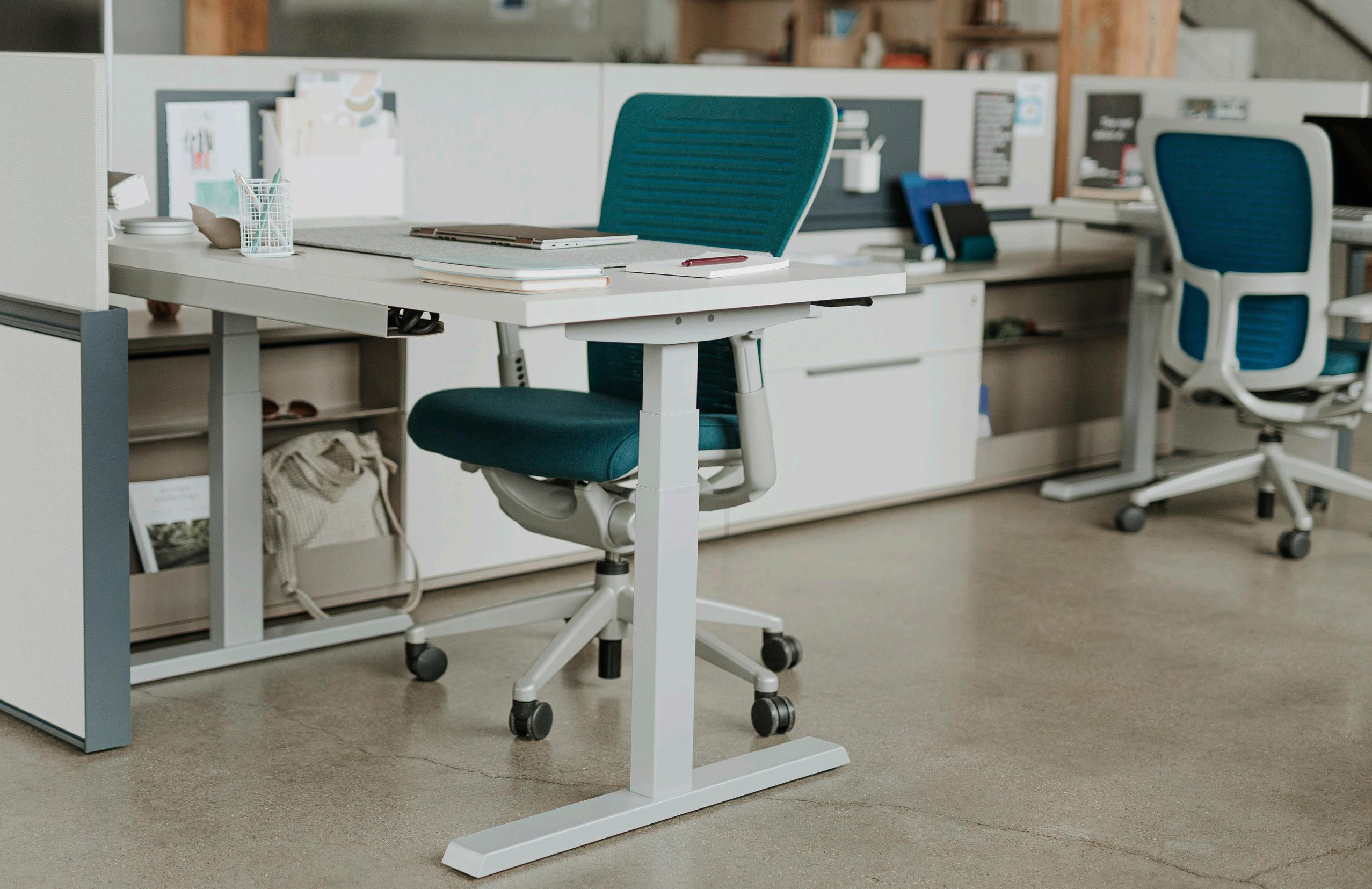
Upside Height Adjustable Tables offer a variety of sizes, options and finishes to fit the needs of each user.
Surface Option:
Upside tables are available with the following surface finish options:
L Laminate
Specifies a top with a laminate finish, requires specification of a laminate finish color.
W Wood
Specifies a top with a wood veneer finish, requires specification of a wood veneer finish color.
Wood Grain Direction
Wood tops are available with natural veneer, quarter cut veneer, rift cut veneer or double cut wood veneer finishes, laminate tops are available with a wood grain laminate finish. See below for wood grain direction.
Edge Option:
Upside tables are available with the following edge options:
J K Laminate Edgeband (3mm Thick)
• For use with Laminate Tops.
• Edgeband is 3mm thick.
• Requires separate specification for Edge Trim Color.
• Only applied to user edge.
Wood Edgeband (3mm Thick)
• For use with Wood Tops.
• Edgeband is 3mm thick.
• Edgeband matches Wood Finish Option.
• Only applied to user edge
Edge Option Location
3mm
Standard Edgeband (1mm Thick)
• Edgeband is 1mm thick.
• Only applied to non-user edges (sides and back edges).
Product Details – Upside Height Adjustable Tables
Overview
Base Option:
Upside Tables require the specification of the base configuration.
• Bases may be configured with (C) C-Leg or (T) T-Leg Base Options.
• Available as a complete table or base only.
Height Adjustment Actuator and Telescoping Column Option:
Upside Tables require the specification of a Height Adjustment Actuator and a Telescoping Base Column Option.
• Actuators may be mounted on left or right side of the table using predrilled holes.
• Actuators are standard with a black housing.
Height Adjustment Actuator/Column Options
Telescoping Base Columns
Adjustment Actuator (Right Hand mounting shown)
Height Adjustment Actuators
Simple Paddle Programmable Paddle
Single Stage Columns with Simple Paddle Adjustment Actuator
Dual Stage Low Columns with Simple Paddle Adjustment Actuator
Single Stage Columns with Programmable Paddle Adjustment Actuator
Dual Stage Low Columns with Programmable Paddle Adjustment Actuator
Telescoping Base Column Finish Specification Matrix
The finish color for the Telescoping Base Column Tubes are determined by the base trim color.
• When the base trim color is specified with a Smooth Non-Metallic paint, the Telescoping Base Tube Column finish will match.
• When the base trim color is specified with a textured, metallic or textured metallic paint finish, the Telescoping Base Column tubes will have a coordinating finish (Exception: Metallic Silver, See Matrix below for specific finishes).
Bases Includes:
• Expandable Frame
• Telescoping Base Columns
• End Brackets
• Feet with Glides (provides a 1/2" of vertical adjustment for leveling)
• Control Box and 9' power cord with NEMA 5-15 plug
Matrix for Telescoping Column Tube Finishes
Product Details – Upside Height Adjustable Tables
Rectangular
C-Leg Base (Option C)
Component Materials/Finishes
COMPONENT NAME
Rectangular Top
C-Leg/ T-Leg Base Assembly
Height Adjustment Actuators
MATERIALS/ FINISHES
Composite board with High Pressure Laminate (HPL) Surface and ABS edgeband.
– Specify Laminate finish/color for the Surface
– Specify Laminate edgeband finish/color for Edge
Frame, Leg, Foot and End Bracket Painted Metal – Specified Base Trim Color
Telescoping Base Columns
Matched with leg finish for Smooth and non-metallic paints, Legs specified with Smooth Metallic, Textured Metallic and Textured paint will have a coordinating finish (See overview page for details).
Glides Standard in Black
Simple Adjustment Actuator
Programmable Adjustment Actuator
Paddle with up/down controls. Standard with black housing.
Paddle with up/down controls and programmable button for storing up to two different programmed heights. Standard with black housing.
be mounted on
Table Lifting Capacity
• Total lifting capacity of table is 250 lbs. including surface.
• Applied weight should be evenly distributed. T-Leg Base (Option T)
Product Numbers, Configurations and Options
*Works with Screen or Monitor Arm; not both
Note • Upside tables are standard with Glides, Casters are available, but must be separately specified and field installed
To Order, Specify:
1 Base Option:
C-Leg Base T-Leg Base
2 Height Adjustment Actuator Option: Single Stage: X Simple Paddl Y Programmable Paddle Dual Stage: U Simple Paddle W Programmable Paddle
3 Model (Color) Option:
N Upside (3 base colors)
G Upside+ (Additional Premium Colors, GSA)
Product Details – Upside Height Adjustable Tables
Rectangular
Dimensions – C-Leg Base (Option C)
Dimensions – T-Leg Base (Option T)
(See chart for available widths)
chart for available widths)
Note
• The dimensions in these charts reflect the installation of the base using the pilot holes provided on the underside of the top .
• The adjustable width of the base allows the legs to be positioned flush to the edge or inset not more than 12" from the edge of the top These custom leg positions are not reflected in the dimensions provided in the charts above
Product Details – Upside Height Adjustable Tables
Base Only
C-Leg Base
Component Materials/Finishes
COMPONENT NAME
C-Leg/ T-Leg Base Assembly
Height Adjustment Actuators
Frame, Leg, Foot and End Bracket
MATERIALS/ FINISHES
• Painted Metal – Specified Base Trim Color Telescoping Base Columns
Glides
Standard Adjustment Actuator
Programmable Adjustment Actuator
• Matched with leg finish for smooth and non-metallic paints, legs specified with smooth metallic, textured metallic and textured paint will have a coordinating finish (See overview page for details).
• Standard in Black
• Paddle with up/down controls.
• Standard with black housing.
• Paddle with up/down controls and programmable button for storing up to two different programmed heights.
• Standard with black housing.
Product Numbers, Configurations and Options
T-Leg Base
To Order, Specify:
1 Model (Color) Option: N Upside (3 base colors) G Upside+ (Additional Premium Colors, GSA)
Expandable Frame
• The width of the expandable frame can range from a minimum of 40 3/16" to a maximum of 71 11/16" wide.
Table Lifting Capacity
• Total lifting capacity of table is 250 lbs. including surface.
• Applied weight should be evenly distributed.
Field Supplied Top Requirements
• Tops may not overhang more than 12" out from the end brackets.
• Upside bases are only for use with rectangle top shapes.
• Tops must accommodate 1" pinch point clearance on all sides.
• Tops must meet NFPA class C flammability rating.
Casters
Casters YES* YES*
Casters YES YES (25 lbs. max)
*Works with Screen or Monitor Arm; not both
Note Upside tables are standard with Glides, Casters may be separately specified and field installed
pinch point clearance is required between side edge and adjacent objects
pinch point clearance is required between the front edge and adjacent objects
Telescoping Base Columns
• Bases are available with Single or Dual Stage Low Telescoping Base Columns.
Dual Stage: Height Adjustment Range: 22.6" minimum height to 48.7" maximum height (including a separately specified 1 3/16" thick top)
Product Details – Upside Height Adjustable Tables
Base Only
Dimensions – C-Leg Base (Option C)
Glides provide 1/2" of vertical adjustment for leveling
Dimensions – T-Leg Base (Option T)
Side View (Single Stage Option)
Side View (Dual Stage Low Option)
Side View (Single Stage Option)
Side View (Dual Stage Low Option)
Note
Glides provide 1/2" of vertical adjustment for leveling
• The dimensions in these charts reflect the installation of the base using the pilot holes provided on the underside of the top
• The adjustable width of the base allows the legs to be positioned flush to the edge or inset not more than 12" from the edge of the top These custom leg positions are not reflected in the dimensions provided in the charts above
Product Details – Upside Height Adjustable Tables
Upside 90° Corner Wrap-Around Top Only
1-Piece Top (52" - 58" wide)
Components and Surface Materials
COMPONENT NAME MATERIALS/ FINISHES
Configurations and Options
2-Piece
To Order Specify:
(52"-58" W)
(52"-58" W)
Edgeband Thickness
• The laminate top is standard with a 3mm edgeband on user edge and 1mm on remaining edges.
Specified Edge Option (3mm Edgeband)
Edgeband Profile (Side View)
Product Details – Upside Height Adjustable Tables
Upside 90° Corner Wrap-Around Top Only
Dimensions
and Sizes
Top View – 1-Piece Top
Depth–Right (See chart for available depths) WIDTH (See chart for available widths)
Width (See chart for available widths)
Depth–Left (See chart for available depths)
Top View – 2-Piece Top
chart for available widths)
(See chart for available widths)
Depth–Right (See chart for available depths) Worksurface
(See chart for available depths)
Product Details – Upside Height Adjustable Tables
Upside 90° Corner Wrap-Around Extended Top Only
1-Piece Top (46" - 58" wide)
Components and Surface Materials COMPONENT NAME MATERIALS/ FINISHES
90° Corner Wrap-Around Extended Top
Configurations and Options
2-Piece Top (64" - 76" Wide)
To Order Specify:
Depth and Orientation Option 1
23" Deep Tops
29" Deep Tops
Edgeband Thickness
• The laminate top is standard with a 3mm edgeband on user edge and 1mm on remaining edges.
Edgeband Profile (Side View)
Product Details – Upside Height Adjustable Tables
Upside 90° Corner Wrap-Around Extended Top Only
Dimensions and Sizes
Top View – 1-Piece Top
Length (See chart for available length)
Width (See chart for available widths)
Depth–Left (See chart for available depths)
Top View – 2-Piece Top
Depth–Right (See chart for available depths)
Width (See chart for available widths)
Depth–Left (See chart for available depths) Length (See chart for available length)
Depth–Right (See chart for available depths)
Product Details – Upside Height Adjustable Tables
Upside 90° Corner Wrap-Around Transitional Extended Top Only
1-Piece Top (46"-58" wide)
2-Piece Top (64"-76" Wide)
Edgeband Thickness
• The laminate top is standard with a 3mm edgeband on user edge and 1mm on remaining edges.
Specified Edge Option (3mm Edgeband)
1mm Square Edgeband
USER EDGE
Edgeband Profile (Side View)
Components and Surface Materials
COMPONENT NAME MATERIALS/ FINISHES
90° Corner Wrap-Around Exnteded Top
Composite board with High Pressure Laminate (HPL) Surface and ABS edgeband.
– Specify Laminate finish/color for the Surface
– Specify Laminate edgeband finish/color for Edge
Configurations and Options
To Order Specify:
Depth and Orientation Option 1 Indicates Laminate Wood Grain Direction
Product Details – Upside Height Adjustable Tables
Upside 90° Corner Wrap-Around Transitional Extended Top Only
Dimensions and Sizes
Top View – 1-Piece Top
(See chart for available length)
(See chart for available widths)
Top View – 2-Piece Top
(See chart for available length)
for
Product Details – Upside Height Adjustable Tables
Upside 120° Corner Wrap-Around Top Only
Components and Surface Materials
COMPONENT NAME MATERIALS/ FINISHES
90° Corner Wrap-Around Exnteded Top
Configurations and Options
Edge Profile Locations
• The laminate top is standard with a 3mm edgeband on user edge and 1mm on remaining edges.
Specified Edge Option (3mm Edgeband)
1mm Square Edgeband
Edgeband Profile (Side View)
Product Details – Upside Height Adjustable Tables
Upside 120° Corner Wrap-Around Top Only
Dimensions and Sizes
Top View – 1-Piece Top
Product Details – Upside Height Adjustable Tables
Upside Base Only for 90° or 120° Top
Components and Surface Materials
Base Configurations
Configurations and Options
• Base only requires separately specified/field supplied top.
• Base can be adjusted to either 90° or 120° configuration
• Maximum work top overhang allowed is 6".
• Select a top that accommodates 1" pinch point clearance on all sides and meets at least a NFPA class C flammability rating.
To Order Specify:
Product Details – Upside Height Adjustable Tables
Upside Base Only for 90° or 120° Top Dimensions and Sizes
Top View
Front View
Single Stage
Front View
Dual Stage
Product Details – Upside Height Adjustable Tables
Belong Suspended Pedestal – Box/File
Components and Surface Materials
COMPONENT NAME
MATERIALS/ FINISHES
Case, Back and Fronts Painted Steel – Specify Trim Color
Configurations and Options
File Configurations and Capacities
• Drawers Include full extension steel ball-bearing slides.
• The File Drawer accommodates side-to-side letter filing (does not accommodate legal filling).
Suspended Pedestal Applications
Designed for use on the following products and configurations:
• Upside Height Adjustable Tables
– 29" Deep Tops (only)
– C-Leg Base with Single or Dual Stage Telescoping Base Columns
• Planes LT Height Adjustable Tables
– 29" Deep Tops (Only)
– C-Leg Base with single stage telescoping base columns (Only)
• Planes Height Adjustable Tables
– 29" Deep Tops (Only)
– C-Leg Base with single stage telescoping base columns (Only
• Intuity Benching
• Panel-mounted Adaptable Worksurfaces
Dimensions and Sizes
Belong Suspended Pedestal – Open with Box Drawer
Components and Surface Materials
COMPONENT NAME MATERIALS/ FINISHES
Case, Back and Fronts
Box Drawer
Painted Steel – Specify Trim Color
Painted
Configurations and Options
KU PD – 16 09 – S N S U N N
Suspended Pedestal Applications
Designed for use on the following products and configurations:
• Upside Height Adjustable Tables
– 29" Deep Tops (only)
– C-Leg Base with Single or Dual Stage Telescoping Base Columns
• Planes LT Height Adjustable Tables
– 29" Deep Tops (Only)
– C-Leg Base with single stage telescoping base columns (Only)
• Planes Height Adjustable Tables
– 29" Deep Tops (Only)
– C-Leg Base with single stage telescoping base columns (Only
Height Adjustable Tables In L Configurations with Panel Hung Worksurfaces
A pinch point clearance of at least 1” must be maintained on all sides of a Height Adjustable Table. When components are surrounding the Height Adjustable Table, either the dimension of the Table must be reduced or the width of the panel hung worksurface must be reduced.
Height Adjustable Table Applications – Without Screens
Don’t
• Height Adjustable Tables (without screens) installed adjacent to a panel with a 1" pinch point clearance cannot have a power receptacles located within the adjustment range of the table.
• The standard 1" for pinch point clearance between the table edge and the receptacle is not sufficient to prevent collisions between the edge of the table and cords plugged into the receptacle. Moving the top of the table up and down could cause a collision that damages the panel, the receptacle and the cord.
Height Adjustable Table Applications – Without Screens
• To prevent possible interference between power cords and the top, locate power receptacles below the Height Adjustment range of the of the table.
• Placing a panel power receptacle in the base raceway position is recommended to avoid interference.
Single Stage (height includes 1 3/16" thick top)
• Minimum Table Height 27.40"
• Maximum Table Height 46.61"
• Height Adjustment Range 19.21"
Dual Stage (height includes 1 3/16" thick top)
• Minimum Table Height 22.60"
• Maximum Table Height 48.74"
• Height Adjustment Range 26.14"
• If a panel mounted power receptacle is located within height adjustment range of an adjustable height table, additional clearance must be provided to prevent collisions between the top and power cords plugged into the receptacle.
• Ensure height adjustable tops clear any objects (such as the plug and the bend radius of a power cord) and then add an additional 1" of clearance to prevent any pinch points or interference.
Position Table to clear the power cord and add an additional 1" for pinch point clearance.
Caution
Since the type of plugs and power cords are at the discretion of the user, determining the proper clearance may be difficult. Because of this, it is highly recommended that receptacles be placed below the adjustment range of the table or adjacent to the table when possible.
Clearance of Obstruction (Plug and bend radius of power cord - dimensions will vary.)
Table Alignment with Adjacent Components
• Be aware that adding additional clearance may inhibit alignment of the top with adjacent components.
Side View Top View
Clearance of Plug and Power Cord Plus an additional 1" for pinch point clearance.
Height Adjustable Table does not align with Return Panel
Height Adjustable Table does not aligns with adjacent Adaptable Worksurfaces
Height Adjustable Table Applications – Without Screens
• To prevent possible interference between power cords and the top, locate power receptacles adjacent the height adjustment range of the of the top. Do
Compose Panel Application
To avoid interference with the top, the Power/Data receptacles are placed adjacent to the table.
Table Alignment with Adjacent Components
• By locating power receptacles adjacent to the height adjustment range of the top, the table will be able to maintain the standard 1" pinch point clearance allowing it to align with adjacent adaptable worksurface and return panels.
Top View
Power Receptacle (Located adjacent to Table)
Height Adjustable Table Panel
Adaptable Worksurface
1" Pinch Point Clearance
Height Adjustable Table Aligns with Return Panel
Height Adjustable Table Aligns with adjacent Adaptable Worksurfaces
• Height Adjustable Tables with attached screens installed adjacent to a panels with a 1" pinch point clearance cannot have a power receptacle located within the adjustment range of the top with screen.
• The 1" for pinch point clearance between the screen and the receptacle is not sufficient to prevent collisions between the edge of the screen and cords plugged into the receptacle. Moving the top up and down could cause a collision that damages the panel, the receptacle, the cord and the screen.
Height Adjustable Table Applications – With Screens
Recommended panel power locations for Height Adjustable Tables with an attached screen: – In the Base Raceway to prevent possible interference between cords and the Attached Screen. – Adjacent to the Table/Screen (allow 1" pinch point clearance).
Compose Panel Application
Receptacle
1" Pinch Point Clearance
Adjustment Range with Screens
Side View 1" Pinch Point Clearance
Single Stage (height includes 1 3/16" thick top)
• Minimum Table Height 27.40"
• Maximum Table Height 46.61"
• Height Adjustment Range 19.21"
Dual Stage (height includes 1 3/16" thick top)
• Minimum Table Height 22.60"
• Maximum Table Height 48.74"
• Height Adjustment Range 26.14"
• If a power receptacle is located within the height adjustment range of a table, additional clearance must be provided to prevent shearing of power cords.
• Ensure the height adjustable table and the attached screen clears any objects (such as the plug and the bend radius of a power cord) and then add an additional 1" of clearance to prevent any pinch points or interference.
Compose Panel Application
Position Table and screen to clear the power cord and add an additional 1" for pinch point clearance.
Table Height Adjustment Range (Including Screen)
Caution
Since the type of plugs and power cords are at the discretion of the user, determining the proper clearance may be difficult. Because of this, it is highly recommended that receptacles be placed below or adjacent to the table when possible. Side View Top View 1" Pinch Point Clearance 1 1/2" (Back edge of top to back edge of screen bracket)
Object Clearance (Plug and bend radius of power cord - dimensions will vary.)
Table Alignment with Adjacent Components
• Be aware adding additional clearance may inhibit alignment of the top with adjacent components.
Upside electric height adjustable products include tables offered in a variety of configurations. Tables are 3rd party certified through Intertek to be compliant to UL 962 and CSA C22.2 No. 68. The components comprising the base assembly consist of some or all the following:
Feet
Feet are present on table units and consist of a sheet metal weldment with glides that offer 1/2” of adjustment. Optional caster kits are available for two leg tables.
Columns
Columns are constructed of roll-formed steel, the inner and outer tubes are powder coat painted. Single post columns include a glide with 1/2” adjustment. Columns adjustment options include:
• Height-Adjustable Electric Table, Dual-Stage Electric: Electric adjustment from 22.6”–48.7” at a rate of 1.4” per second. Two-column table supports 250 lbs., including weight of surface.
• Height-Adjustable Electric Table, Single-Stage Electric: Electric adjustment from 27.4” – 46.6” at a rate of 1.4” per second. Two-column table supports 250 lbs., including weight of surface.
Supports
Two column table support includes: angled steel end brackets at each end and two dual steel telescoping tubes placed between columns, both end brackets and tubes are attached to surface and columns with metal screws. Three column table supports include:
• Angled steel end brackets attached to surface and outside end columns using metal screws.
• Z-shaped steel bracket that allows for both 90-degree and 120-degree table configurations and attaches to single post and surface using steel screws.
• Two dual steel telescoping tubes placed between outside column and post column on user side attached to surface and columns using steel screws.
• One single steel telescoping tube placed between post and outside end column on visitor side attached to surface and columns using steel screws.
Two piece 90-degree surfaces also include a flat bracket to bridge surfaces and attaches to surfaces using metal screws.
Controller
Electric height adjustable tables include an electronic system that controls via a hand-switch the operation of the columns providing enhanced gyro-sensor collision detection, container and shelf stop settings, and calibration/ initialization capabilities for smooth operation of the table travel. Controllers have a 2 minute on/18 minute off duty cycle.
Paddle Control (Hand-switch)
Hand-switch options include a standard up/down paddle or a programmable paddle with up/down, two memory settings, and an OLED digital height display. Programmable paddle allows for the setting of container and shelf stops, setting a move reminder, and activating a handset lock. Programmable switch can also display error codes for troubleshooting purposes.
Table Top Construction
Laminate and veneer table top cores are 1 3/16" (30.2mm) thick and are made with an engineered composite panel with a minimum 90% wood fiber content with at least 10% post-consumer and 80% pre-consumer wood fiber bonded with resin. These worksurfaces/tops are 3rd party certified compliant with GREENGUARD® and ANSI/ BIFMA Standards for Low Emitting Products. The composite panel is 3rd party certified compliant with California Air Resource Board requirements for Phase 2 formaldehyde emission levels and includes wood fiber sourced from FSC certified forests using the 70% FSC Mix Credit System.
Laminate surfaces are balanced construction with high-pressure laminate on the top, a laminate backer on the bottom and are available with the following plastic edges:
• 0.125” (3mm) radius edge band on the user edge capped with a 0.039” (1mm) thick edge band on the remaining edge(s)
Wood veneer surfaces are balanced construction with wood veneer on the top, a balancing backer on the bottom and are available with the following wood edges:
• 0.125” (3mm) radius edge band on the user edge capped with a 0.028” (.7mm) thick edge band on the remaining edge(s).
Greenguard Testing
Upside Height Adjustable Tables meet or exceed the test requirements in ANSI/BIFMA X7.1-Standard for Formaldehyde and TVOC Emissions of Low-Emitting Office Furniture Systems and Seating.
Planes
Product Details
Height Adjustable Tables
Product Details – Planes Height Adjustable Tables
Introduction
Planes is a compelling table and ancillary product line that supports a wide variety of spaces with easy and effortless functionality. From conference rooms to individual workstations, Planes enables visual consistency throughout any work environment with its application breadth, top shapes, size range, and base choices. In addition, Planes is part of Haworth’s Integrated Palette, which provides a holistic design and finish offering for effective solutions.
The Planes Collection is more than just tables, Planes offers:
• Collaborative Tables: Y-Leg, X-Base, and Disc Base
• Training Tables: C-Leg
• Height Adjustable Tables: Freestanding and Bench
• Conference Tables: Interior Leg, Perimeter Leg, and Column Base
• Carts
• Credenzas
• Easels, Information Boards, Horizontal Wall Rail System
Planes allows easy functionality with the ability to flip, store, conceal, connect, adjust, and plug in effortlessly:
• Flip – Reconfigure spaces with the flip top option
• Store –Save valuable floor space with the nesting feature
• Conceal – Cleanly manage wires and cables
• Connect – Gang tables together effortlessly
• Adjust – Raise and lower worksurfaces with manual or electrical height adjustment mechanisms
• Plug In – Power tables individually or distribute between Global Design:
Planes offers a clean, simple, crisp aesthetic; designed in conjunction with Haworth Design Studio and Daniel Figueroa of Bad Munder, Germany. Planes is truly a global product line.
Sustainability:
Planes is BIFMA level® 3, GREENGUARD certified, contributes LEED points, and includes FSC wood.
Product Details – Planes Height Adjustable Tables
Overview – Configurations and Options
Planes Height Adjustable Tables offer a variety of table sizes shapes and adjustment options to fit each user. Each table offers different set of features and options.
Height Adjustable Table Components and Configurations
with Standard
Mechanical Height Adjustment Options (Incremental or Hand Crank)
Incremental Hand Crank
Adjustable Height Ranges By Type
ADJUSTMENT TYPE MINIMUM HEIGHT MAXIMUM HEIGHT
Incremental Adjustment With Button Screws Table
Crank Adjustment with Retractable Hand Crank
Ranges:
Electric/Powered Height Adjustment Mechanisms (Standard and Programmable Touch Pad)
Standard Up/Down Touch Pad Electric Adjustment
Programmable Touch Pad Electric Adjustment
Note
• The power draw for a powered height adjustable table with two legs is 10 Watts when stationary and 4 Amps while raising worksurface with a 175 pound surface load
• The power draw for a powered height adjustable table with three legs is 10 Watts when stationary and 8 Amps while raising worksurface with a 175 pound surface load
• Standard Touch Pad Actuator and Programmable Touch Pad Actuator can be mounted on left or right side
Telescoping Base Tube Finish Specification Matrix
The finish color for the Telescoping Base Tubes is determined by the paint finish specified for the Leg/Foot.
• When the Leg/Foot is specified with a Smooth Non-Metallic paint, the Telescoping Base Tube finish will match.
• When the Leg/Foot is specified with a Textured or Metallic paint finish, the Telescoping Base Tube finish will have a coordinating finish (See Matrix below for specific finishes).
Matrix for Telescoping Base Tubes Finishes Paint
Metallic Champagne TR-MC
Smooth Metallic Paint
Textured Metallic Paint
Smooth Paint (Non-Metallic)
Grout TR-TG Platinum TR-P
Cement TR-TY Brownstone TR-1R
Hellenic TR-HE Brownstone TR-1R
Pitch TR-TF Black TR-F
Argent TR-AR Smoke TR-E
Telescoping Base Tube Finish will match Base Trim Color specified for the Foot/Leg
Telescoping Base Tube Leg Foot
Product Details – Planes Height Adjustable Tables
Overview – Shelf / Container Stops
Height Adjustable Tables with an electric height adjustment mechanism may be field programmed with shelf/ container stops within the standard height adjustment range to avoid interference with objects above or below the table (shelves/pedestals).
STEP 1 Set table to desired height
STEP 2 Press and hold up and down buttons until you hear (2) clicks
Note
• To remove container stop, press and hold up and down buttons until you hear (1) click
• Container/Shelf Stops can be set with Standard Up/Down Touch Pad
Height Adjustable Table Load Capacities
• Table load capacity (including top) – weight should be evenly distributed.
– 29” deep table supports a 27” high Belong screen and a monitor up to 50 lbs.
– 23” deep table supports either a 27” high Belong screen or a monitor up to 25 lbs.
• Height adjustable tables not designed to accept Adjustable Keyboard Pads, suspended or attached pedestals.
Product Details – Planes Height Adjustable Tables
Overview – Wood Grain Direction
Wood Grain Direction for Natural Veneer, Quarter Cut Veneer, Rift Cut Veneer, Double Cut Wood Veneer and Wood Grain Laminate
Arrows indicate Wood Grain Direction
Rectangle
90° Angled 90° Straight 90° Split Top
90° Wrap Around
90° Notched
Corner 120° Wrap-Around
Corner 90° Notched One-Piece Top
Corner 90° Wrap-Around Two-Piece Top Left Hand Orientation
Corner 90° Wrap-Around Two-Piece Top Right Hand Orientation
Corner
90° Wrap-Around One-Piece Top
Corner
90° Wrap-Around Extended One-Piece Top
Corner
90° Notched Extended One-Piece Top
Corner 90° Wrap-Around Two-Piece Top Left Hand Orientation
Corner 90° Wrap-Around Two-Piece Top Right Hand Orientation
Bench
Double Sided
Bench
Single Sided
Corner 90° Wrap-Around Extended Two-Piece Top Left Hand Orientation
Corner 90° Wrap-Around Extended Two-Piece Top Right Hand Orientation
Corner 90° Notched Extended Two-Piece Top Left Hand Orientation
Corner 90° Notched Extended Two-Piece Top Right Hand Orientation
Product Details – Planes Height Adjustable Tables
Overview – Edge Options
Edge Profile Options for Laminate Tops
Edgeband (Option J)
• For use with Laminate Tops
Knife Edge (Option F)
• For use with Laminate Tops
Edge Profile Options for Wood Veneer Tops
Wood Edgeband (Option K)
• For use with Wood Tops
1 3/16”
Knife Edge (Option U)
• For use with Wood Tops
Note The specified edge profile option is applied to the user edge only, all other edges are standard with a 1mm square edgeband
Product Details – Planes Height Adjustable Tables
Overview – Pinch Point Clearance
• Planes Height Adjustable Table Tops are designed to allow a 1” pinch point clearance and to accommodate cables.
• Tops are 1” less in depth and 2” less in width than standard Adaptable Worksurfaces sizes.
• Height Adjustable Tables must be positioned 1” from adjacent Adaptable Worksurfaces and Panels to provide required pinch point clearance.
Panel Application with Standard Adaptable Worksurfaces
Adaptable Component Worksurfaces
Panel Application with Standard Adaptable Worksurfaces and a Height Adjustable Corner Table with 1” Pinch Point Clearance
Panel Application with Standard Adaptable Worksurfaces and a Height Adjustable Table – Rectangle with 1” Pinch Point Clearance
Adaptable Component Worksurface
Height Adjustable Table – 90° Straight
Adaptable Component Worksurface
Height Adjustable Table – Rectangle
Adaptable Component Worksurfaces
Product Details – Planes Height Adjustable Tables
Rectangular
Rectangle Top
Height Adjustment Mechanism (Shown with Standard Touch Pad option)
Height Adjustment Mechanisms
Incremental Adjustment With Button Screws
Crank Adjustment with Retractable Hand Crank
Adjustment with Standard Up/ Down Touch Pad
Adjustment with Programmable Touch Pad
Adjustable Height Ranges By Type
Component Materials/Finishes
COMPONENT NAME MATERIALS/ FINISHES
Laminate Top –Specify surface color and separate edge finish color (J) Edgeband (F) Knife Edge
Rectangular Top
Leg, Foot and Attachment Arm
C Leg Base Assembly
Telescoping Base Tube
J Rail
Incremental Leg
Hand Crank
Height Adjustment Mechanism
Electric Adjustment with Standard Up/Down Touch Pad
Electric Adjustment with Programmable Touch Pad
Wood Top – Specify a single surface and edge finish color (K) Edgeband (U) Knife Edge
• Painted Metal – Specified Base Trim Color
• Matched with leg finish for Smooth and non-metallic paints, Legs specified with Metallic and Textured paint will have a coordinating finish (See overview page for details).
• Painted Metal – Standard in black
• Includes bright zinc button head screws.
• Thumbscrew replacement for button head screw is available; separately specified, standard in black.
• Hand Crank is standard in black.
• Retracts under top when not in use.
• Touch pad with up/down controls.
• Includes Actuator with black housing, Control Box with black housing and 9 1/2' long black power cord.
• Touch pad with up/down controls and programmable buttons for storing up to four different programmed heights.
• Includes Actuator with black housing, Control Box with black housing and 9 1/2' long black power cord.
• Standard in Black
(See chart for available depths) Dimensions Top View
Note
• Hand Crank, Standard Touch Pad Actuator and Programmable Touch Pad Actuator can be mounted on left or right side
• Table may be field programmed with shelf/ container stops within the standard height range to avoid interference with objects (shelves/pedestals) .
• Total lifting capacity of tables with an electric adjustment mechanism is 250 lbs including the top
• Applied weight should be evenly distributed .
• See Price List for Top weights
Edge Profile Locations
• The specified edge profile option is applied to the user edge only, all other edges are standard with a 1mm square edgeband.
Specified Edge Option (Knife Edge/ 3mm Edgeband)
1mm Square Edgeband
(See chart for adjustable height ranges by
Front View Side View
Product Details – Planes Height Adjustable Tables
90° Angled
Height Adjustment Mechanism (Shown with Standard Touch Pad option)
Component Materials/Finishes
COMPONENT NAME MATERIALS/ FINISHES
90° Angled Top Laminate Top –Specify surface color and separate edge finish color (J) Edgeband (F) Knife Edge
Wood Top –Specify a single surface and edge finish color (K) Edgeband (U) Knife Edge
C Leg Base Assembly
Adjustment Mechanisms
Adjustment Mechanism
Leg, Foot and Attachment Arm
Telescoping Base Tube
• Painted Metal – Specified Trim Color
• Matched with leg finish for Smooth and non-metallic paints, Legs specified with Metallic and Textured paint will have a coordinating finish (See overview page for details). J Rail
Incremental Leg Adjustment
Electric Adjustment with Standard Up/Down Touch Pad
Electric Adjustment with Programmable Touch Pad
Adjustable Height Ranges By Type
Note
• Standard Touch Pad Actuator and Programmable Touch Pad Actuator can be mounted on left or right side
• Table may be field programmed with shelf/container stops within the standard height range to avoid interference with objects (shelves/ pedestals)
• Total lifting capacity of tables with an electric adjustment mechanism is 250 lbs including the top
• Applied weight should be evenly distributed
• See Price List for Top weights
Edge Profile Locations
• The specified edge profile option is applied to the user edge only, all other edges are standard with a 1mm square edgeband.
Specified Edge Option (Knife Edge/ 3mm Edgeband)
1mm Square Edgeband
Painted Metal – Standard in Black
• Includes bright zinc Button head screws.
• Thumbscrew replacement for button head screw is available; separately specified, standard in black.
• Touch pad with up/down controls.
• Standard with black housing.
• Includes Actuator with black housing, Control Box with black housing and 9 1/2” long black power cord.
• Touch pad with up/down controls and programmable buttons for storing up to four different programmed heights.
• Includes Actuator with black housing, Control Box with black housing and 9 1/2” long black power cord.
• Standard in Black
Product Details – Planes Height Adjustable Tables
90° Straight
Adjustment Mechanism (Shown with Standard Touch Pad option)
Component Materials/Finishes
Laminate Top –Specify surface color and separate edge finish color (J) Edgeband (F) Knife Edge
90° Straight Top
C Leg Base Assembly Leg, Foot and Attachment Arm
TACA-4040-_ _SNCDB
Height Adjustment Mechanisms
Incremental Adjustment With Button Screws Electric Adjustment with Standard Up/ Down Touch Pad
Adjustment with Programmable Touch Pad
Adjustable Height Ranges By Type
Note
• Standard Touch Pad Actuator and Programmable Touch Pad Actuator can be mounted on left or right side .
• Table may be field programmed with shelf/container stops within the standard height range to avoid interference with objects (shelves/ pedestals) .
• Total lifting capacity of tables with an electric adjustment mechanism is 250 lbs including the top
• Applied weight should be evenly distributed .
• See Price List for Top weights .
Edge Profile Locations
• The specified edge profile option is applied to the user edge only, all other edges are standard with a 1mm square edgeband.
Specified Edge Option (Knife Edge/ 3mm Edgeband)
1mm Square Edgeband
Wood Top –Specify a single surface and edge finish color (K) Edgeband (U) Knife Edge
• Painted Metal – Specified Trim Color Telescoping Base Tube
J Rail
Incremental Leg Adjustment
Height Adjustment Mechanism
Electric Adjustment with Standard Up/Down Touch Pad
Electric Adjustment with Programmable Touch Pad
Glides
• Matched with leg finish for Smooth and non-metallic paints, Legs specified with Metallic and Textured paint will have a coordinating finish (See overview page for details).
• Painted Metal – Standard in Black
• Includes bright zinc Button head screws.
• Thumbscrew replacement for button head screw is available; separately specified, standard in black.
• Touch pad with up/down controls.
• Standard with black housing.
• Includes Actuator with black housing, Control Box with black housing and 9 1/2” long black power cord.
• Touch pad with up/down controls and programmable buttons for storing up to four different programmed heights.
• Includes Actuator with black housing, Control Box with black housing and 9 1/2” long black power cord.
• Standard in Black
Product Details – Planes Height Adjustable Tables
90° Wrap Around
Adjustment Mechanism (Shown with Standard Touch Pad option)
Component Materials/Finishes
COMPONENT NAME
90° Wrap Around
Arm
Height Adjustment Mechanisms
Incremental Adjustment With Button Screws
Adjustment with Standard Up/ Down Touch Pad
Adjustment with Programmable Touch Pad
Adjustable Height Ranges By Type
Adjustment Mechanism
Leg, Foot and Attachment Arm
Telescoping Base Tube
Rail
Incremental Leg Adjustment
Electric Adjustment with Standard Up/Down Touch Pad
Electric Adjustment with Programmable Touch Pad
MATERIALS/ FINISHES
Laminate Top –Specify surface color and separate edge finish color (J) Edgeband (F) Knife Edge
Wood Top –Specify a single surface and edge finish color (K) Edgeband (U) Knife Edge
• Painted Metal – Specified Trim Color
• Matched with leg finish for Smooth and non-metallic paints, Legs specified with Metallic and Textured paint will have a coordinating finish (See overview page for details).
• Painted Metal – Standard in Black
• Includes bright zinc Button head screws.
• Thumbscrew replacement for button head screw is available; separately specified, standard in black.
• Touch pad with up/down controls.
• Standard with black housing. Includes Actuator with black housing, Control Box with black housing and 9 1/2” long black power cord.
• Touch pad with up/down controls and programmable buttons for storing up to four different programmed heights.
• Includes Actuator with black housing, Control Box with black housing and 9 1/2” long black power cord.
• Standard in Black
Note
• Standard Touch Pad Actuator and Programmable Touch Pad Actuator can be mounted on left or right side
• Table may be field programmed with shelf/container stops within the standard height range to avoid interference with objects (shelves/ pedestals)
• Total lifting capacity of tables with an electric adjustment mechanism is 250 lbs including the top
• Applied weight should be evenly distributed
• See Price List for Top weights
Edge Profile Locations
• The specified edge profile option is applied to the user edge only, all other edges are standard with a 1mm square edgeband.
Specified Edge Option (Knife Edge/ 3mm Edgeband)
1mm Square Edgeband
Product Details – Planes Height Adjustable Tables
90° Notched
Adjustment
(Shown with Standard Touch Pad option)
Component Materials/Finishes
COMPONENT NAME
90° Notched Top
Leg, Foot and Attachment Arm
C Leg Base Assembly
Height Adjustment Mechanisms
Incremental Adjustment With Button Screws
Height Adjustment Mechanism
Telescoping Base Tube
J Rail
Incremental Leg Adjustment
Electric Adjustment with Standard Up/Down Touch Pad
Electric Adjustment with Programmable Touch Pad
MATERIALS/ FINISHES
Laminate Top –Specify surface color and separate edge finish color (J) Edgeband (F) Knife Edge
Wood Top –Specify a single surface and edge finish color (K) Edgeband (U) Knife Edge
• Painted Metal – Specified Trim Color
• Matched with leg finish for Smooth and non-metallic paints, Legs specified with Metallic and Textured paint will have a coordinating finish (See overview page for details).
• Painted Met al – Standard in Black
• Includes bright zinc Button head screws.
• Thumbscrew replacement for button head screw is available; separately specified, standard in black.
• Touch pad with up/down controls.
• Standard with black housing. Includes Actuator with black housing, Control Box with black housing and 9 1/2” long black power cord.
• Touch pad with up/down controls and programmable buttons for storing up to four different programmed heights.
• Includes Actuator with black housing, Control Box with black housing and 9 1/2” long black power cord.
• Standard in Black
Note
• Standard Touch Pad Actuator and Programmable Touch Pad Actuator can be mounted on left or right side
• Table may be field programmed with shelf/container stops within the standard height range to avoid interference with objects (shelves/ pedestals)
• Total lifting capacity of tables with an electric adjustment mechanism is 250 lbs including the top
• Applied weight should be evenly distributed
• See Price List for Top weights
Edge Profile Locations
• The specified edge profile option is applied to the user edge only, all other edges are standard with a 1mm square edgeband.
Specified Edge Option (Knife Edge/ 3mm Edgeband)
1mm Square Edgeband
Product Details – Planes Height Adjustable Tables
Corner 90° Notched – 1-Piece Top
Component Materials/Finishes
COMPONENT NAME
Corner 90° Notched (One Piece Top)
Leg, Foot and Attachment Arm
Adjustment Mechanism (Shown with Programmable Touch Pad option)
Height Adjustment Mechanisms
Incremental Adjustment With Button Screws
Crank Adjustment with Retractable Hand Crank
Adjustment with Standard Up/ Down Touch Pad
Adjustment with Programmable Touch Pad
Adjustable Height Ranges By Type
C Leg Base Assembly
Height Adjustment Mechanism
Telescoping Base Tube
J Rail
Incremental Leg Adjustment
Crank Adjustment
Electric Adjustment with Standard Up/Down Touch Pad
Electric Adjustment with Programmable Touch Pad
MATERIALS/ FINISHES
Laminate Top –Specify surface color and separate edge finish color (J) Edgeband (F) Knife Edge
Wood Top –Specify a single surface and edge finish color (K) Edgeband (U) Knife Edge
• Painted Metal – Specified Trim Color
• Matched with leg finish for Smooth and non-metallic paints, Legs specified with Metallic and Textured paint will have a coordinating finish (See overview page for details).
• Painted Metal – Standard in Black
• Includes bright zinc Button head screws.
• Thumbscrew replacement for button head screw is available; separately specified, standard in black.
• Hand Crank is standard in black. Retracts under top when not in use.
• Touch pad with up/down controls.
• Standard with black housing.
• Includes Actuator with black housing, Control Box with black housing and 9 1/2” long black power cord.
• Touch pad with up/down controls and programmable buttons for storing up to four different programmed heights.
• Includes Actuator with black housing, Control Box with black housing and 9 1/2” long black power cord.
Glides Standard in Black
Dimensions
Note
• The Hand Crank, Standard Touch Pad Actuator and Programmable Touch Pad Actuator can be mounted on left or right side
• The table may be field programmed with shelf/container stops within the standard height range to avoid interference with objects (shelves/ pedestals)
• Total lifting capacity of tables with an electric adjustment mechanism is 300 lbs . including the top .
• Applied weight should be evenly distributed .
• See Price List for Top weights
Edge Profile Locations
• The specified edge profile option is applied to the user edge only, all other edges are standard with a 1mm square edgeband.
Specified Edge Option (Knife Edge/ 3mm Edgeband)
1mm Square Edgeband
(See chart for available widths)
(See chart for available depths)
(See chart for available lengths)
DEPTH–LEFT (See chart for available depths)
(See chart for adjustable
Product Details – Planes Height Adjustable Tables
Corner 90° Notched – 2-Piece Top
Attachment Arm
Component Materials/Finishes
Corner 90° Notched Top (Two Piece Top)
Height Adjustment Mechanism (Shown with Programmable Touch Pad option)
Height Adjustment Mechanisms
Incremental Adjustment With Button Screws Electric Adjustment with Standard Up/ Down Touch Pad Hand Crank Adjustment with Retractable Hand Crank Electric Adjustment with Programmable Touch Pad
Adjustable Height Ranges By Type
Note
• The Hand Crank, Standard Touch Pad Actuator and Programmable Touch Pad Actuator can be mounted on left or right side
• The table may be field programmed with shelf/container stops within the standard height range to avoid interference with objects (shelves/ pedestals) .
• Total lifting capacity of tables with an electric adjustment mechanism is 300 lbs including the top
• Applied weight should be evenly distributed
• See Price List for Top weights
Table Orientation
• 2-piece tops are handed. The seamless primary user side determines the handedness.
C Leg Base Assembly
Left Handed Options: (E) 23" Deep Top with Left Hand Orientation (F) 29" Deep Top with Left Hand Orientation
Edge Profile Locations
Right Handed Options
23" Deep Top with Right Hand Orientation
29" Deep Top with Right Hand Orientation
• The specified edge profile option is applied to the user edge only, all other edges are standard with a 1mm square edgeband.
Specified
Edge Option (3mm Edgeband)
1mm Square Edgeband
FINISHES
Laminate Top –Specify surface color and separate edge finish color (J) Edgeband
Wood Top –Specify a single surface and edge finish color (K) Edgeband
Leg, Foot and Attachment Arm Painted Metal – Specified Trim Color
Telescoping Base Tube
J Rail
Incremental Leg Adjustment
Crank Adjustment
Height Adjustment Mechanism
Electric Adjustment with Standard Up/Down Touch Pad
Electric Adjustment with Programmable Touch Pad
Dimensions Top View
• Matched with leg finish for Smooth and non-metallic paints, Legs specified with Metallic and Textured paint will have a coordinating finish (See overview page for details).
• Painted Metal – Standard in black
• Includes bright zinc Button head screws.
• Thumbscrew replacement for button head screw is available; separately specified, standard in black.
• Hand Crank is standard in black
• Retracts under top when not in use.
• Touch pad with up/down controls.
• Standard with black housing.
• Includes Actuator with black housing, Control Box with black housing and 9 1/2” long black power cord.
• Touch pad with up/down controls and programmable buttons for storing up to four different programmed heights.
• Includes Actuator with black housing, Control Box with black housing and 9 1/2” long black power cord.
• Standard in Black
chart for adjustable height
Product Details – Planes Height Adjustable Tables
Corner 90° Wrap-Around – 1-Piece Top
Component Materials/Finishes
Corner 90° Wrap-Around (One Piece Top)
Leg, Foot and Attachment Arm
Adjustment Mechanism (Shown with Programmable Touch Pad option)
Height Adjustment Mechanisms
Incremental Adjustment With Button Screws
Crank Adjustment with Retractable Hand Crank
Adjustment with Standard Up/ Down Touch Pad
Adjustment with Programmable Touch Pad
Adjustable Height Ranges By Type
C Leg Base Assembly
Height Adjustment Mechanism
Telescoping Base Tube
Note
• The Hand Crank, Standard Touch Pad Actuator and Programmable Touch Pad Actuator can be mounted on left or right side .
• The table may be field programmed with shelf/container stops within the standard height range to avoid interference with objects (shelves/ pedestals)
• Total lifting capacity of tables with an electric adjustment mechanism is 300 lbs . including the top
• Applied weight should be evenly distributed
• See Price List for Top weights
Edge Profile Locations
• The specified edge profile option is applied to the user edge only, all other edges are standard with a 1mm square edgeband.
Specified Edge Option (Knife Edge/ 3mm Edgeband)
1mm Square Edgeband
FINISHES
Laminate Top –Specify surface color and separate edge finish color (J) Edgeband (F) Knife Edge
Wood Top –Specify a single surface and edge finish color (K) Edgeband (U) Knife Edge
• Painted Metal – Specified Trim Color
• Matched with leg finish for Smooth and non-metallic paints, Legs specified with Metallic and Textured paint will have a coordinating finish (See overview page for details).
J Rail Painted Metal – Standard in Black
Incremental Leg Adjustment
Crank Adjustment
Electric Adjustment with Standard Up/Down Touch Pad
Electric Adjustment with Programmable Touch Pad
• Includes bright zinc Button head screws.
• Thumbscrew replacement for button head screw is available; separately specified, standard in black.
• Hand Crank is standard in black.
• Retracts under top when not in use.
• Touch pad with up/down controls.
• Standard with black housing.
• Includes Actuator with black housing, Control Box with black housing and 9 1/2” long black power cord
• Touch pad with up/down controls and programmable buttons for storing up to four different programmed heights.
• Includes Actuator with black housing, Control Box with black housing and 9 1/2” long black power cord.
Standard in Black
Glides
(See chart for available widths)
WORKSURFACE DEPTH–RIGHT (See chart for available depths)
Worksurface Depth–Left (See chart for available depths)
(See chart for adjustable height ranges by type)
Glides provide 1/2” of vertical leveling adjustment
Product Details – Planes Height Adjustable Tables
Corner 90° Wrap-Around – 2-Piece Top
Component Materials/Finishes
Corner 90° Wrap-Around (Two Piece Top)
Leg, Foot and Attachment Arm
C Leg Base Assembly
Incremental Adjustment With Button Screws
Adjustable Height Ranges By Type Height Adjustment Mechanisms
Electric Adjustment with Standard Up/ Down Touch Pad
Hand Crank Adjustment with Retractable Hand Crank Electric Adjustment with Programmable Touch Pad
Height Adjustment Mechanism
Telescoping Base Tube
J Rail
Incremental Leg Adjustment
Crank Adjustment
Electric Adjustment with Standard Up/Down Touch Pad
Electric Adjustment with Programmable Touch Pad
Laminate Top –Specify surface color and separate edge finish color (J) Edgeband
Wood Top –Specify a single surface and edge finish color (K) Edgeband
• Painted Metal – Specified Trim Color
• Matched with leg finish for Smooth and non-metallic paints, Legs specified with Metallic and Textured paint will have a coordinating finish (See overview page for details).
• Painted Metal – Standard in Black
• Includes bright zinc Button head screws.
• Thumbscrew replacement for button head screw is available; separately specified, standard in black.
• Hand Crank is standard in black.
• Retracts under top when not in use.
• Touch pad with up/down controls.
• Standard with black housing.
• Includes Actuator with black housing, Control Box with black housing and 9 1/2” long black power cord.
Touch pad with up/down controls and programmable buttons for storing up to four different programmed heights.
• Includes Actuator with black housing, Control Box with black housing and 9 1/2” long black power cord. Glides Standard in Black
Note
• Hand Crank, Standard Touch Pad Actuator and Programmable Touch Pad Actuator can be mounted on left or right side
• The table may be field programmed with shelf/container stops within the standard height range to avoid interference with objects (shelves/pedestals) .
• Total lifting capacity of tables with an electric adjustment mechanism is 300 lbs including the top .
• Applied weight should be evenly distributed
• See Price List for Top weights .
Table Orientation
• 2-piece tops are handed. The seamless primary user side determines the handedness.
Seamless Primary User Side (Left Hand) Seamless
User Side (Right Hand)
Left Handed Options:
(E) 23" Deep Top with Left Hand Orientation
(F) 29" Deep Top with Left Hand Orientation
Edge Profile Locations
Right Handed Options
(H) 23" Deep Top with Right Hand Orientation
(J) 29" Deep Top with Right Hand Orientation
• The specified edge profile option is applied to the user edge only, all other edges are standard with a 1mm square edgeband.
Specified
Edge Option (3mm Edgeband)
1mm Square
Edgeband
Product Details – Planes Height Adjustable Tables
Corner 90° Wrap-Around Extended – 1-Piece Top
Corner 90° Wrap-Around Extended (One Piece Top) J
Attachment
Arm
Height Adjustment Mechanism (Shown with Programmable Touch Pad option)
TACE-4064-_ _SNC_ _
Height Adjustment Mechanisms
Incremental Adjustment With Button Screws Electric Adjustment with Standard Up/ Down Touch Pad
Hand Crank Adjustment with Retractable Hand Crank Electric Adjustment with Programmable Touch Pad
Adjustable Height Ranges By Type
Component Materials/Finishes
COMPONENT NAME
Corner 90° Wrap-Around Extended (One Piece Top)
Leg, Foot and Attachment Arm
C Leg Base Assembly
Height Adjustment Mechanism
Telescoping Base Tube
Note
• Hand Crank, Standard Touch Pad Actuator and Programmable Touch Pad Actuator can be mounted on left or right side
• The table may be field programmed with shelf/container stops within the standard height range to avoid interference with objects (shelves/pedestals) .
• Total lifting capacity of tables with an electric adjustment mechanism is 300 lbs . including the top .
• Applied weight should be evenly distributed
• See Price List for Top weights
Table Orientation
• Extended table handedness is determined by length side of table from seated position.
Left Handed Options:
(E) 23" Deep Top with Left Hand Orientation
(F) 29" Deep Top with Left Hand Orientation
Edge Profile Locations
Right Handed Options (H) 23" Deep Top with Right Hand Orientation (J) 29" Deep Top with Right Hand Orientation
• The specified edge profile option is applied to the user edge only, all other edges are standard with a 1mm square edgeband.
Specified Edge Option (Knife Edge/ 3mm Edgeband)
1mm Square Edgeband
MATERIALS/ FINISHES
Laminate Top –Specify surface color and separate edge finish color (J) Edgeband (F) Knife Edge
Wood Top – Specify a single surface and edge finish color (K) Edgeband (U) Knife Edge
• Painted Metal – Specified Trim Color
Matched with leg finish for Smooth and non-metallic paints, Legs specified with Metallic and Textured paint will have a coordinating finish (See overview page for details).
J Rail Painted Metal – Standard in Black
Incremental Leg Adjustment
Crank Adjustment
Electric Adjustment with Standard Up/Down Touch Pad
Electric Adjustment with Programmable Touch Pad
• Includes bright zinc Button head screws.
• Thumbscrew replacement for button head screw is available; separately specified, standard in black.
• Hand Crank is standard in black.
• Retracts under top when not in use.
• Touch pad with up/down controls.
• Standard with black housing.
• Includes Actuator with black housing, Control Box with black housing and 9 1/2” long black power cord.
• Touch pad with up/down controls and programmable buttons for storing up to four different programmed heights.
• Includes Actuator with black housing, Control Box with black housing and 9 1/2” long black power cord. Glides
Dimensions Top View
WORKSURFACE DEPTH–LEFT (See chart for available depths)
Front View
• Standard in Black
(See chart for available lengths)
(See chart for adjustable height ranges by type) WIDTH (See chart for available widths)
Glides provide 1/2” of vertical leveling
WORKSURFACE DEPTH–RIGHT (See chart for available depths)
Height Adjustment Mechanism (Shown with Programmable Touch Pad option)
Height Adjustment Mechanisms
Corner 90° Wrap-Around Extended (2-Piece Top)
Component Materials/Finishes
COMPONENT NAME
Corner 90° Wrap-Around Extended (Two Piece Top)
Leg, Foot and Attachment Arm
C Leg Base
Assembly
Incremental Adjustment With Button Screws
Hand Crank Adjustment with Retractable Hand Crank
Electric Adjustment with Standard Up/ Down Touch Pad
Electric Adjustment with Programmable Touch Pad
Height
Adjustment
Mechanism
Telescoping Base Tube
J Rail
Incremental Leg Adjustment
Crank Adjustment
Electric Adjustment with Standard Up/Down Touch Pad
Electric Adjustment with Programmable Touch Pad
Glides
Dimensions Top View
Note
• Hand Crank, Standard Touch Pad Actuator and Programmable Touch Pad Actuator can be mounted on left or right side .
• The table may be field programmed with shelf/container stops within the standard height range to avoid interference with objects (shelves/pedestals)
• Total lifting capacity of tables with an electric adjustment mechanism is 300 lbs including the top .
• Applied weight should be evenly distributed
• See Price List for Top weights .
Table Orientation
• Two-piece tops are handed.
• The seamless primary user side of the table (side without seam) determines the handedness from a seated position.
Left Right
Seamless Primary User Side (Left Hand)
Left Handed Options:
(E) 23" Deep Top with Left Hand Orientation
(F) 29" Deep Top with Left Hand Orientation
Edge Profile Locations
Seamless Primary User Side (Right Hand)
Right Handed Options (H) 23" Deep Top with Right Hand Orientation (J) 29" Deep Top with Right Hand Orientation
• The specified edge profile option is applied to the user edge only, all other edges are standard with a 1mm square edgeband.
Specified Edge Option (3mm Edgeband)
1mm Square Edgeband
MATERIALS/ FINISHES
Laminate Top –Specify surface color and separate edge finish color (J) Edgeband Wood Top –Specify a single surface and edge finish color (K) Edgeband
• Painted Metal – Specified Trim Color
• Matched with leg finish for Smooth and non-metallic paints, Legs specified with Metallic and Textured paint will have a coordinating finish (See overview page for details).
• Painted Metal – Standard in Black
• Includes bright zinc Button head screws.
• Thumbscrew replacement for button head screw is available; separately specified, standard in black.
• Hand Crank is standard in black.
• Retracts under top when not in use.
Touch pad with up/down controls.
• Standard with black housing.
• Includes Actuator with black housing, Control Box with black housing and 9 1/2” long black power cord.
• Touch pad with up/down controls and programmable buttons for storing up to four different programmed heights.
• Includes Actuator with black housing, Control Box with black housing and 9 1/2” long black power cord.
• Standard
3/16”
3/4”
Wide x 70” Length Only)
Product Details – Planes Height Adjustable Tables
Corner 90° Notched Extended – 1 Piece Top
Attachment Arm
Component Materials/Finishes
COMPONENT NAME
90° Angled Top
• Standard core only
Leg, Foot and Attachment Arm
C Leg Base Assembly
TACP-4064-_ _SNC_ _
Height Adjustment Mechanisms
Height Adjustment Mechanism
Telescoping Base Tube
J Rail
Incremental Leg Adjustment
Crank Adjustment
Electric Adjustment with Standard Up/Down Touch Pad
MATERIALS/ FINISHES
Laminate Top –Specify surface color and separate edge finish color (J) Edgeband (F) Knife Edge
Wood Top – Specify a single surface and edge finish color (K) Edgeband (U) Knife Edge
• Painted Metal – Specified Trim Color
• Matched with leg finish for Smooth and non-metallic paints, Legs specified with Metallic and Textured paint will have a coordinating finish (See overview page for details).
• Painted Metal – Standard in black.
• Includes bright zinc Button head screws.
• Thumbscrew replacement for button head screw is available; separately specified, standard in black.
• Hand Crank is standard in black.
• Retracts under top when not in use.
• Touch pad with up/down controls.
• Standard with black housing.
• Includes Actuator with black housing, Control Box with black housing and 9 1/2” long black power cord black.
Incremental Adjustment With Button Screws
Hand Crank Adjustment with Retractable Hand Crank Electric Adjustment with Programmable Touch Pad
Electric Adjustment with Standard Up/ Down Touch Pad
Adjustable Height Ranges By Type
Electric Adjustment with Programmable Touch Pad
• Touch pad with up/down controls and programmable buttons for storing up to four different programmed heights.
• Includes Actuator with black housing, Control Box with black housing and 9 1/2” long black power cord black. Glides Standard in Black
Dimensions Top View
WORKSURFACE DEPTH–LEFT
(See chart for available depths)
5/16” E
Note
• Hand Crank, Standard Touch Pad Actuator and Programmable Touch Pad Actuator can be mounted on left or right side
• The table may be field programmed with shelf/container stops within the standard height range to avoid interference with objects (shelves/pedestals)
• Total lifting capacity of tables with an electric adjustment mechanism is 300 lbs including the top
• Applied weight should be evenly distributed
• See Price List for Top weights
Table Orientation
• Extended table handedness is determined by length side of table from seated position.
Front View HEIGHT
(See chart for adjustable height ranges by type) WIDTH (See chart for available widths) LENGTH (See chart for available lengths)
Glides provide 1/2” of vertical leveling
WORKSURFACE DEPTH–RIGHT (See chart for available depths)
Left Handed Options:
(E) 23" Deep Top with Left Hand Orientation
(F) 29" Deep Top with Left Hand Orientation
Edge Profile Locations
Right Handed Options
(H) 23" Deep Top with Right Hand Orientation (J) 29" Deep Top with Right Hand Orientation
• The specified edge profile option is applied to the user edge only, all other edges are standard with a 1mm square edgeband.
Height Adjustment Mechanism (Shown with Programmable Touch Pad option)
Height Adjustment Mechanisms
Incremental Adjustment With Button Screws
Crank Adjustment with Retractable Hand Crank
Adjustment with Standard Up/ Down Touch Pad
Adjustment with Programmable Touch Pad
Adjustable Height Ranges By Type
Component Materials/Finishes
COMPONENT NAME
Corner 90° Notched Extended (Two Piece Top)
Leg, Foot and Attachment
MATERIALS/ FINISHES
Laminate Top –Specify surface color and separate edge finish color (J) Edgeband Wood Top –Specify a single surface and edge finish color (K) Edgeband
• Painted Metal – Specified Trim Color Telescoping
J Rail
Incremental Leg Adjustment
Crank Adjustment
• Matched with leg finish for Smooth and non-metallic paints, Legs specified with Metallic and Textured paint will have a coordinating finish (See overview page for details).
• Painted Metal – Standard in Black
• Includes bright zinc Button head screws.
• Thumbscrew replacement for button head screw is available; separately specified, standard in black.
• Hand Crank is standard in black.
• Retracts under top when not in use.
Electric Adjustment with Standard Up/Down Touch Pad Touch pad with up/down controls.
Electric Adjustment with Programmable Touch Pad
Dimensions Top View
Note
• Hand Crank, Standard Touch Pad Actuator and Programmable Touch Pad Actuator can be mounted on left or right side .
• The table may be field programmed with shelf/container stops within the standard height range to avoid interference with objects (shelves/pedestals)
• Total lifting capacity of tables with an electric adjustment mechanism is 300 lbs including the top
• Applied weight should be evenly distributed .
• See Price List for Top weights .
Table Orientation
• Two-piece tops are handed.
• The seamless primary user side of the table (side without seam) determines the handedness from a seated position.
• Standard with black housing.
• Includes Actuator with black housing, Control Box with black housing and 9 1/2” long black power cord.
• Touch pad with up/down controls and programmable buttons for storing up to four different programmed heights.
• Includes Actuator with black housing, Control Box with black housing and 9 1/2” long black power cord.
• Standard in Black
Left Handed Options:
(E) 23" Deep Top with Left Hand Orientation
(F) 29" Deep Top with Left Hand Orientation
Edge Profile Locations
Right Handed Options (H) 23" Deep Top with Right Hand Orientation (J) 29" Deep Top with Right Hand Orientation
• The specified edge profile option is applied to the user edge only, all other edges are standard with a 1mm square edgeband.
Specified
Edge Option (3mm Edgeband)
1mm Square Edgeband
Product Details – Planes Height Adjustable Tables
Corner 120° Wrap-Around
One Piece Top
Component Materials/Finishes
COMPONENT NAME
Corner 120° Wrap-Around (One Piece Top)
Leg, Foot and Attachment Arm
Height Adjustment Ranges By Type Height Adjustment Mechanisms
C Leg Base
Assembly
Height Adjustment
Mechanism
Telescoping Base Tube
J Rail
Incremental Leg Adjustment
Crank Adjustment
Electric Adjustment with Standard Up/Down Touch Pad
Electric Adjustment with Programmable Touch Pad
Glides
FINISHES
Laminate Top –Specify surface color and separate edge finish color (J) Edgeband (F) Knife Edge
Wood Top –Specify a single surface and edge finish color (K) Edgeband (U) Knife Edge
Painted Metal – Specified Trim Color
• Matched with leg finish for Smooth and non-metallic paints, Legs specified with Metallic and Textured paint will have a coordinating finish (See overview page for details).
• Painted Metal – Standard in Black
• Includes bright zinc Button head screws.
• Thumbscrew replacement for button head screw is available; separately specified, standard in black.
• Hand Crank is standard in black.
• Retracts under top when not in use.
• Touch pad with up/down controls.
• Standard with black housing.
• Includes Actuator with black housing, Control Box with black housing and 9 1/2” long black power cord.
• Touch pad with up/down controls and programmable buttons for storing up to four different programmed heights.
• Includes Actuator with black housing, Control Box with black housing and 9 1/2” long black power cord.
• Standard in Black
Note
• The Hand Crank, Standard Touch Pad Actuator and Programmable Touch Pad Actuator can be mounted on left or right side
• The table may be field programmed with shelf/container stops within the standard height range to avoid interference with objects (shelves/pedestals)
• Total lifting capacity of tables with an electric adjustment mechanism is 300 lbs including the top
• Applied weight should be evenly distributed
• See Price List for Top weights
Edge Profile Locations
• The specified edge profile option is applied to the user edge only, all other edges are standard with a 1mm square edgeband.
Specified Edge Option (Knife Edge/ 3mm Edgeband)
1mm Square Edgeband
Product Details – Planes Height Adjustable Tables
Belong Screen – For use with Height Adjustable Tables – Worksurface Mount
• Only for use with Planes Height Adjustable Tables
• Not for use with Planes Height Adjustable Table - Benches
Screen Thickness by Material
Screen
Fabric
Specified fabric color – surface is non-tackable.
Laminate High-pressure laminate surface with 1mm laminate edgeband. Specified surface color and edgeband trim color.
Wood Specified wood veneer surface with 1mm wood edgeband.
Glass
9T-1C Clear Glass Finish (Grade A)
9T-E21 Satin Etched Glass Finish (Grade C)
Markerboard Glossy white markerboard surface with 1mm edgeband.
Attachment Brackets Painted Metal – With Specified Trim Color
Dimensions
Front View (19" High Screen)
HEIGHT
Nominal (Actual) 19" (18.75")
Side View (Single Stage)
WIDTH
(See Chart for available widths)
34" (33.68")
(29.5") or Less
40" (39.68") 36" (35.5") or Less
46” (45.68”) 42” (41.5”) or Less
52” (51.68”) 48” (47.5”) or Less
58” (57.68”) 54” (53.5”) or Less
64” (63.68”) 60” (59.5”) or Less
70” (69.68”) 60” (59.5”) or Less
Front View (27" High Screen)
WIDTH
(See Chart for available widths)
HEIGHT
Nominal (Actual) 27" (26.75")
(35.5”)
(41.5”)
(47.5”)
(53.5”)
(59.5”)
Side View (Single Stage)
SCREEN THICKNESS Varies by Material (See Chart)
(59.5”)
Product Details – Planes Height Adjustable Tables
Cable Management – Wire Management Basket
• The Wire Management Basket is designed for use with height adjustable tables to provide additional wire management and storage.
• Attaches to underside of top and detaches from table without tools.
• Accessible from both sides.
• Mounts to the underside of the top (straddles the J Rails).
Component Materials/Finishes
Dimensions
Accessories – Basket Cover
• The separately specified Basket Cover encloses a side of the basket to provide a more finished aesthetic.
• A Basket Cover can be added to each side of the basket.
• Specify width to match Basket width.
• The covers are painted metal, and may be specified with a trim color to match the table base or with a coordinating color.
• Each Basket Cover is separately specified.
Application Overview
• The Wire Management Basket is designed for use with most height adjustable tables.
• Ensure basket width is less than distance between C-Leg Posts.
• Ensure the mounting bracketry does not interfere with mounting hardware for screens, monitor arms or other worksurface mounted accessories.
• The Basket is designed for use with the following Planes Height Adjustable Tables: – Rectangular Height Adjustable Tables – 90° Corners – 2-Leg – 90° Corners – 3-Leg
• The Basket is NOT for use with the following Planes Height Adjustable Tables due to interference with the base: – Single Sided Height Adjustable Table – Bench – Dual Sided Height Adjustable Table – Bench – 120° Height Adjustable Table – Bench
Product Details – Planes Height Adjustable Tables
Accessories – Collision Sensor
• The installation of a Collision Sensor on a Planes table with electric height adjustment, helps reduce the possible risk of pinching.
• The Collision Sensor is installed on the underside of the top and connects to the motor control unit on the table. After the system is triggered by sensor, the top will automatically move a defined distance in the opposite direction. This helps prevent the possible risk of pinching.
Component Materials/Finishes
Sensor with Cord
• Specify with (1) Cord for tops 58" or less.
• Specify with (2) cords for tops greater than 58" wide
Unit
Note
• The use of a Collision Sensor does not completely eliminate potential pinch point risks or collisions – user should be properly trained and use caution when operating
• Can only be installed on Planes Height Adjustable Tables and Benches controller that is newer than 10-2016
Installation Diagram
• The Sensor Cord is plugged into the Processor Unit and the Metal Bracket on the end is screwed to bottom of the top and the J-rail. For optimal performance the Sensor Cord must be securely fastened.
• The Processor Unit is screwed to the bottom of the top and must be located within reach of the Motor Control.
• The one end of the Connecting Cable is plugged into the Processor Unit and the other end connects to the Motor Control.
Leg, Foot and Attachment Arm Power and Data Channels with Trough
C Leg Base Assembly
Glides
Edge Profile Locations
Height Adjustment Mechanism (Shown with Programmable Touch Pad option)
• The specified edge profile option is applied to the user edge only, all other edges are standard with a 1mm square edgeband.
Specified Edge Option (Knife Edge/ 3mm Edgeband)
1mm Square Edgeband
Screen Applications (Screens are separately specified) Planes Screens – For use with Planes Height Adjustable Benches – Center Mount
• Center Mount Screens attach to the H-Leg base and are Stationary (do not move up and down).
• Only for use with 24", 30" or 36" deep tops, with a 3 5/8" gap between the tops to accommodate the Center Mount Screen.
3 5/8" Gap Between Tops 24", 30" or 36" Deep Tops Center Mount Screen TASC
Belong Screen – For Height Adjustable Benches – Worksurface Mount
• Worksurface Mount Screens attach to the underside of the top allowing them to move up and down with the top.
• Only for use with 23", 29" or 35" deep tops, with a 5 5/8" gap between tops to accommodate the Worksurface Mount Screens.
23", 29" or 35" Deep Tops
5 5/8" Gap Between Tops
Worksurface Mount Screen SUFB
Height Adjustment Mechanism
(See Price List for available mechanism combinations)
Telescoping Base Tubes
J Rail
Crank Adjustment
Electric Adjustment with Standard Up/Down Touch Pad
Electric Adjustment with Programmable Touch Pad
Glides
Wood Grain Direction
MATERIALS/ FINISHES
Laminate Top –Specify surface color and separate edge finish color (J) Edgeband (F) Knife Edge
Wood Top –Specify a single surface and edge finish color (K) Edgeband (U) Knife Edge
Painted Metal – Specified Trim Color
• Matched with leg finish for Smooth and non-metallic paints, Legs specified with Metallic and Textured paint will have a coordinating finish (See Planes overview page for details).
• Painted Metal – Standard in Black
• Hand Crank is standard in black
• Retracts under top when not in use.
• Touch pad with up/down controls.
• Standard with black housing.
• Includes Actuator with black housing, Control Box with black housing and 9 1/2” long black power cord.
• Touch pad with up/down controls and programmable buttons for storing up to four different programmed heights.
• Includes Actuator with black housing, Control Box with black housing and 9 1/2” long black power cord.
• Standard in Black
• Wood Grain Direction for Natural Veneer, Quarter Cut Veneer, Rift
Cut Veneer, Double Cut Wood Veneer and Wood Grain Laminate.
Height Adjustment Mechanisms
Crank Adjustment
Electric Adjustment with Standard Up/Down Touch Pad
Electric Adjustment with Programmable Touch Pad
Arrows indicate Wood Grain Direction
Specification Options for Height Adjustment Mechanisms
Crank Adjustment (Both Tops with Crank Mechanism)
B Crank
Crank and Electric Adjustment
(One Top with Crank Mechanism/One Top with Electric Adjustment Mechanism)
L Crank/Single-Stage Standard Touch Pad
M Crank/Single-Stage Programmable Touch Pad
Electric Adjustment (Both Tops with Electric Adjustment Mechanism)
E Single-Stage Standard Touch Pad
R Single-Stage Programmable Touch Pad
P Dual-Stage Low Standard Touch Pad
S Dual-Stage Low Programmable Touch Pad
Q Dual-Stage High Standard Touch Pad
T Dual-Stage High Programmable Touch Pad
Note
• The Hand Crank, Standard Touch Pad Actuator and Programmable Touch Pad Actuator can be mounted on left or right side
• The table may be field programmed with shelf/container stops within the standard height range to avoid interference with objects (shelves/ pedestals)
• Total lifting capacity for each worksurface with an electric adjustment mechanism is 250 lbs including the worksurface .
Planes Screens – For use with Planes Height Adjustable Benches – Center Mount (Separately Specified)
• Center Mount Screens attach to the Power and Data Channel with Trough and are stationary (they do not move up and down).
• Only for use with 24" or 30" deep tops, which are designed to accommodate a Center Mount Screen. 24" or 30" Deep Tops
3 11/16" between Top and back of Power and Data Channel
C Leg Base Assembly
Leg, Foot and Attachment Arm and Power and Data Channels with Trough
Telescoping Base Tubes
J Rail
Height Adjustment Mechanism (See Price List for available mechanism combinations) Crank Adjustment
Electric Adjustment with Standard Up/Down Touch Pad
Electric Adjustment with Programmable Touch Pad
Glides
MATERIALS/ FINISHES
Laminate Top –Specify surface color and separate edge finish color (J) Edgeband (F) Knife Edge
Wood Top –Specify a single surface and edge finish color (K) Edgeband (U) Knife Edge
Painted Metal – Specified Trim Color
• Matched with leg finish for Smooth and non-metallic paints, Legs specified with Metallic and Textured paint will have a coordinating finish (See overview page for details).
• Painted Metal – Standard in Black
• Hand Crank is standard in black
• Retracts under top when not in use.
• Touch pad with up/down controls.
• Standard with black housing.
• Includes Actuator with black housing, Control Box with black housing and 9 1/2” long black power cord.
• Touch pad with up/down controls and programmable buttons for storing up to four different programmed heights.
• Includes Actuator with black housing, Control Box with black housing and 9 1/2” long black power cord.
• Standard in Black
Height Adjustment Mechanisms
Crank Adjustment
Electric Adjustment with Standard Up/Down Touch Pad
Electric Adjustment with Programmable Touch Pad
Specification Options for Height Adjustment Mechanisms
Crank Adjustment (Both Tops with Crank Mechanism)
B Crank
T Dual-Stage High Programmable Touch Pad Attachment Arm
Belong Screen – For Height Adjustable Benches – Worksurface Mount (Separately Specified)
• Top Surface Mount Screens attach to the underside of the top allowing them to move up and down with the top.
• Only for use with 23" or 29" deep tops, which are designed to accommodate a Worksurface Mount Screen.
23" or 29" Deep Tops Center Mount Screen TASC
Top Surface Mount Screen SUFB
4 11/16" between Top and back of Power and Data Channel
Electric Adjustment (Both Tops with Electric Adjustment Mechanism)
E Single-Stage Standard Touch Pad
R Single-Stage Programmable Touch Pad
P Dual-Stage Low Standard Touch Pad
S Dual-Stage Low Programmable Touch Pad
Q Dual-Stage High Standard Touch Pad
Note
• The Hand Crank, Standard Touch Pad Actuator and Programmable Touch Pad Actuator can be mounted on left or right side
• The table may be field programmed with shelf/container stops within the standard height range to avoid interference with objects (shelves/ pedestals) .
• Total lifting capacity for each worksurface with an electric adjustment mechanism is 250 lbs . including the worksurface .
Laminate Top –Specify surface color and separate edge finish color (J) Edgeband (F) Knife Edge
Wood Top –Specify a single surface and edge finish color (K) Edgeband (U) Knife Edge
H Leg Base Assembly
Height Adjustment Mechanism
(Shown with Standard Touch Pad option)
Screen Applications
Planes Screens – For use with Planes Height Adjustable Benches – Center Mount
(Separately Specified)
• Center Mount Screens attach to the H-Leg base and are Stationary (they do not move up and down).
• Only for use with 24" or 30" deep tops, which are designed with a 3 5/8" gap between tops to accommodate the Center Mount Screen.
• Specify screen width to match bench width.
Belong Screen – For Height Adjustable Benches – Worksurface Mount (Separately Specified)
• Worksurface Mount Screens attach to the underside of the top allowing them to move up and down with the top.
• Only for use with 23" or 29" deep tops, which are designed with a 5 5/8" gap between tops to accommodate mounting of Worksurface Mount Screens.
Height Adjustment Mechanism
(See Price List for available mechanism combinations)
Glides
H-Leg, Corner Assembly, Attachment Arm, and Power and Data Channels with Trough
Telescoping Base Tubes
J Rail
Electric Adjustment with Standard Up/Down Touch Pad
Electric Adjustment with Programmable Touch Pad
• Painted Metal – Specified Base Trim Color
• Matched with leg finish for Smooth and non-metallic paints, Legs specified with Metallic and Textured paint will have a coordinating finish (See overview page for details).
• Painted Metal – Standard in Black
• Touch pad with up/down controls.
• Standard with black housing.
• Includes Actuator with black housing, Control Box with black housing and 9 1/2” long black power cord.
• Touch pad with up/down controls and programmable buttons for storing up to four different programmed heights. Includes Actuator with black housing, Control Box with black housing and 9 1/2” long black power cord.
• Standard in Black
Height Adjustment Mechanisms
Electric Adjustment with Standard Up/Down Touch Pad Electric Adjustment with Programmable Touch Pad
Specification Options for Height Adjustment Mechanisms
Electric Adjustment (Both Tops with Electric Adjustment Mechanism)
E Single-Stage Standard Touch Pad
R Single-Stage Programmable Touch Pad
P Dual-Stage Low Standard Touch Pad
S Dual-Stage Low Programmable Touch Pad
Q Dual-Stage High Standard Touch Pad
T Dual-Stage High Programmable Touch Pad
Note
• Standard Touch Pad Actuator and Programmable Touch Pad Actuator can be mounted on left or right side
• The table may be field programmed with shelf/container stops within the standard height range to avoid interference with objects (shelves/ pedestals)
.
• Total lifting capacity for each worksurface with an electric adjustment mechanism is 300 lbs . including the worksurface
• Applied weight should be evenly distributed
• See Price List for worksurface weights
• A separately specified 28" long Jumper is required to distribute power between Power Distribution Assemblies
This chart shows the number of communication cables that can be routed through specific pathways. Cable capacities are based on 0.20" (5 mm), 0.25" (6 mm), and 0.30"(8 mm) diameter cables at 60% and 40% fill capacity.
TIA/EIA 569 suggests a cable fill of 40% for planning and up to 60% for unplanned or future additions. The TIA category designations for cable are not size specific but typically the higher the category number the larger the diameter the cable is. As a general rule a Category 5e (Enhanced) cable is approximately 0.20" in diameter, the Category 6 0.25", and a Category (Augmented) 0.30". The actual diameter will vary depending on manufacturer and whether it is a plenum rated cable or riser (PVC) cable.
¹ Cable capacity through the trough may be impacted by the transition tray where two benches connect as the capacity of that tray is less than the tray on the bench.
² The cable capacities for Planes HAB top feeds were calculated at 1.8 square inches even though the openings are much larger. The brackets on the middle run block the routing a bit and the bend radius restricts the capacity.
• Specify desired screen material and finish/color (fabric, laminate, wood or glass)
Step 3 – Specify Electrical Components
Choose appropriate electrical system for the application:
• Hardwired (consists of top feed pole, junction boxes with field supplied wire and receptacles)
• Power Base (Haworth's integrated modular power system)
– Choose Power Configuration (do not mix)
• 3 Circuit (supports as many as three separate 20 Amp rated circuits from one power feed.)
• 4 Circuit (supports as many as four separate 20 Amp rated circuits from one power feed.)
– Specify POWER IN Components:
• Up from the Floor (Base Feed Cover and Infeed Harness)
• Down from the Ceiling (Top Feed – End-of-Run or Middle-of-Run)
– Specify POWER THROUGH Components:
• Specify proper number of Utility Tray Power Retrofit Kit (ensure width matches worksurface width –specify 3 or 4 Circuit - Do not mix)
• Specify appropriate number and type of Transition Tray (Single-Sided Tray, Dual-Sided Tray, Tray for use with Top Feed, or Tray for use with Top Feed and Center Mount Screens).
• Specify Jumper (28" or 30" wide depending on application – 3 or 4 Circuit - Do not mix)
– Specify POWER OUT Components:
• Determine number of receptacles needed (each Power Distribution Assembly supports up to 4 receptacles – 2 on each side)
• Specify 15 AMP or 20 AMP Receptacles
Additional Considerations – for Planes Height Adjustable Benches:
• Planes Height Adjustable Bench worksurfaces finishes are available in laminate (Option L) or wood (Option W).
• Worksurface edge details are offered in square and knife edge for both laminate and wood worksurface finishes.
• Mixing edge details in a single bench run is not recommended due to aesthetic differences.
Edge Profile Options for Laminate Tops (Option L)
Edgeband (Option J)
Knife Edge (Option F)
Edge Profile Options for Wood Veneer Tops (Option W)
Wood Edgeband (Option K)
Wood Knife Edge (Option U)
Don't
• Mixing edge details in a single bench run is not recommended due to aesthetic differences.
Height Adjustment Options
Planes Height Adjustable Benches offer a variety of adjustment mechanisms and heights.
Crank Adjustment Electric Adjustment with Standard Up/Down Touch Pad Electric Adjustment with Programmable Touch Pad
Crank Adjustment
(Only available with Dual and Single-Sided Benches)
B Crank
Crank and Electric Adjustment
(Only available with Dual-Sided Benches)
L Crank/Single-Stage Standard Touch Pad
M Crank/Single-Stage Programmable Touch Pad
Electric Adjustment (Available with all Benches)
E Single-Stage Standard Touch Pad
R Single-Stage Programmable Touch Pad
P Dual-Stage Low Standard Touch Pad
S Dual-Stage Low Programmable Touch Pad
Q Dual-Stage High Standard Touch Pad
T Dual-Stage High Programmable Touch Pad
Don't
Adjustable Height Ranges by Type
Planes HAT-01
Note
• Height Adjustment Actuators (Crank, Standard Touch Pad or Programmable Touch Pad) may be mounted on left or right side of table using predrilled holes
Planes HAT-01
• The power and data channels with troughs of tables with single stage height adjustable legs and dual stage height adjustable legs do not align. Tables with single and dual stage height adjustable legs should not be used together in the same benching applications.
The Planes Height Adjustable Table – Bench (HAB) is available in a variety of depths and widths to meet the needs of most users. Separately specified screens require the specification of specific worksurface depths.
Worksurface Depth Considerations for Screen Applications:
• Worksurface Mounted Screens – Requires 23", 29" or 35" deep benching worksurfaces.
• Center Mounted Screens – Recommend 24", 30" or 36" deep benching worksurfaces.
Planes Center Mount Screen with Single Sided Bench
POWER IN – Base Feed Cover – Vertical and Infeed Harness
• Power is brought into the Planes Height Adjustable Bench using a separately specified Infeed Harness, a separately specified Base Feed Cover - Vertical may be add for a more finished aesthetic. Infeed Harness (Separately Specified) EUEH
Single Stage Bench
Base Feed Cover TA01-BSFD-S Infeed Harness EUEH-0087-_
Dual Stage Bench
Base Feed Cover TA01-BSFD-D Infeed Harness EUEH-0087-_
Base Feed Cover Vertical (Separately Specified)
Note
• Base Feed Cover/Infeed Harness may be used with both Dual-Sided, Single-Sided or 120° Benches
POWER-IN – End-of-Run Top Feed (3-Circuit, 4-Circuit or Hardwired)
• Power is brought down from the ceiling into the end of a Planes height adjustable benching run using a separately specified End-of-Run Top Feed.
Single Stage Bench Top Feed and Cover EAET-_ _ 00-S_
Dual Stage Bench Top Feed and Cover EAET-_ _ 00-D_
End-of-Run Top Feed (Includes End-of-Run Transition Tray)
EAET-C000-S3
EAET-C000-S2
EAET-C000-SC
Note
• End-of-Run Top Feeds may be used with both Dual-Sided, SingleSided or 120° Benches
POWER-IN – Middle-of-Run Top Feed / Transition Tray for use with Middle-of-Run Top Feed
• Power is brought down from the ceiling using a separately specified Middle-of-Run Top Feed. The Top Feed is installed between dual sided benches (middle-of-run) into a separately specified Transition Tray for Middle-ofRun Top Feed.
• The Transition Tray for Middle-of-Run top feed creates a 2" Gap between the benches and is not for use applications using Center Mount Screens.
Middle-of-Run – Top Feed
EAET-C00C-S3
EAET-C00C-S2
EAET-C00C-SC
Single Stage Bench
(With No Center Mount Screens)
Top Feed – Middle-of-Run
EAET-_ _ 0C-S_
Transition Tray – For use with Middle-of-Run Top Feed
TA01-HBTT-MT
Dual Stage Bench
(With No Center Mount Screens)
Top Feed and Cover
EAET-_ _ 0C-D_
Transition Tray – For use with Middle-of-Run Top Feed
TA01-HBTT-MT
Transition Tray - For Middle-of-Run Top Feed (Separately Specified TA01-HBTT-MT)
Transition Tray creates a 2" Gap between worksurfaces for Pinch Point Clearance
Note
• Middle-of-Run Top Feeds and Transition Trays are not for use with Single Sided Benches .
• A 28" Jumper is required for routing power through the Transition Tray between Utility Tray Retrofit Kits
POWER-IN – Middle-of-Run Top Feed / Transition Tray for use with Center Mount Screens & Middle-of-Run Top Feed
• Power is brought down from the ceiling using a separately specified Middle-of-Run Top Feed. The Top Feed is installed between dual sided benches (middle-of-run) into a separately specified Transition Tray For use with Center Mount Screens and Middle-of-Run, Top Feed.
• The Transition Tray For use with Center Mount Screens and Middle-of-Run, Top Feed creates a 4" Gap between the benches to accommodate the Top Feed and prevent interference with the Center Mount Screens.
Middle-of-Run Top Feed
EAET-C00C-S3
EAET-C00C-S2 EAET-C00C-SC
Center Mount Screens (Separately Specified)
TASC-_ _58-F TASC-_ _58-L
Single Stage Bench
(With No Center Mount Screens)
Top Feed – Middle-of-Run
EAET-_ _ 0C-S_
Transition Tray – For use with Center Mount Screens and Middle-of-Run, Top Feed
TA01-HBTT-MTS
Center Mount Screens
TASC-18_ _-F
Dual Stage Bench
(With No Center Mount Screens)
Top Feed and Cover
EAET-_ _ 0C-D_
Transition Tray – For use with Center Mount Screens and Middle-of-Run, Top Feed
TA01-HBTT-MTS
Center Mount Screens
TASC-18_ _-F
Transition Tray For use with Center Mount Screens and Middle-of-Run, Top Feed (Separately Specified TA01-HBTT-MTS)
Transition Tray creates a 4" Gap between worksurfaces to accommodate screens and Top feed
Note
• Middle-of-Run Top Feeds and Transition Trays are not for use with Single Sided Benches .
• A 30" Jumper is required for routing power through the Transition Tray between Utility Tray Retrofit Kits
• Power is routed through dual-sided and 120° benching applications using a matching width Utility Tray Power Retrofit Kit, a 28" long Jumper and a Height Adjustable Bench Transition Tray (all are separately specified).
• The Transition Tray connects the benches together, creates a 2" gap between worksurfaces and provides a channel to route the Jumper.
• The Jumper is used to distribute power between multiple Utility Tray Power Retrofit Kits by connecting to the Power Distribution Assembly.
• The Utility Tray Power Retrofit Kit is installed in the data channel of the bench. The Transition Tray connects the benches together and provides a channel to route the Jumper. The Jumper connects to multiple Utility Tray Retrofit Kits to supply power through the benching run.
Dual Sided-Benching Application
Power Distribution Assembly (Included with Power Retrofit Kit)
Dual-Sided Bench
Utility Tray Power Retrofit Kit (Separately Specified)
EUEK-0042-_S
Jumper – 28" Long (Separately Specified) EUEJ-00_ _-_
• Power is routed through single-sided benching applications using a matching width Utility Tray Power Retrofit Kit, a 28" long Jumper and a Height Adjustable Bench Transition Tray – Asymmetrical (all are separately specified).
• The Transition Tray – Asymmetrical connects the benches together, creates a 2" gap between worksurfaces and provides a channel to route the Jumper.
• The Jumper is used to distribute power between multiple Utility Tray Power Retrofit Kits by connecting to the Power Distribution Assembly (included with Retrofit Kit).
• The Utility Tray Power Retrofit Kit is installed in the data channel of the bench. The Transition Tray connects the benches together and provides a channel to route the Jumper. The Jumper connects to multiple Utility Tray Retrofit Kits to supply power through the benching run.
Single-Sided Bench
Power Distribution Assembly (Included with Power Retrofit Kit)
Utility Tray Power Retrofit Kit (Separately Specified)
EUEK-0042-_S
Single-Sided Benching Application
Dual-Sided / Single-Sided Benching Application
Jumper – 28" Long (Separately Specified) EUEJ-00_ _-_
• Power access on Height Adjustable Benches are provided by Triplex Receptacles installed on a Power Distribution Assembly (PDA is included with the separately specified Utility Tray Power Retrofit Kit). Users can access the receptacles below the worksurfaces through cutouts in the wire management trough.
• Each Power Distribution Assembly accommodates up to (4) Triplex Receptacles (2 on each side).
Power Distribution Assembly (Included with Power Retrofit Kit)
• Height Adjustable Benches include a Data Channel with Troughs which are designed to accommodate Power Base Electrical Components.
• The height of the Data Channels with Troughs is tied to the configuration of the Telescoping Posts. Single-stage posts place the Data Channel with Troughs higher above the floor than Dual-stage posts.
• Ensure all Base Feed Covers and Top Feeds are specified to match the Telescoping Post configuration of the Bench (single-stage or dual-stage) to ensure proper alignment.
This page intentionally left blank .
Technical Specifications
Planes Height Adjustable Tables and Benches
Technical Specifications – Planes Height Adjustable Tables and Benches
Table Top Construction
Laminate and veneer table top cores are 1 3/16" (30.2mm) thick and are made with an engineered composite panel with a minimum 90% wood fiber content with at least 10% post-consumer and 80% pre-consumer wood fiber bonded with resin. These worksurfaces/tops are 3rd party certified compliant with GREENGUARD® and ANSI/ BIFMA Standards for Low Emitting Products. The composite panel is 3rd party certified compliant with California Air Resource Board requirements for Phase 2 formaldehyde emission levels and includes wood fiber sourced from FSC certified forests using the 70% FSC Mix Credit System.
Laminate surfaces are balanced construction with high-pressure laminate on the top, a laminate backer on the bottom and are available with the following plastic edges:
• 0.125” (3mm) radius edge band on the user edge capped with a 0.039” (1mm) thick edge band on the remaining edge(s)
• 0.125" (3mm) radius edgeband on the user edge with a 2" deep reverse chamfer capped with a 0.039" (1mm)thick edgeband on the remaining edges. The exposed wood composite material on the bottom of the surface is sealed with a clear finish.
Wood veneer surfaces are balanced construction with wood veneer on the top, a balancing backer on the bottom and are available with the following wood edges:
• 0.125” (3mm) radius edge band on the user edge capped with a 0.028” (.7mm) thick edge band on the remaining edge(s).
• 0.125" (3mm) radius edgeband on the user edge with a 2" deep reverse chamfer capped with a 0.028" (.7mm) thick edgeband on the remaining edges. The exposed wood composite material is sealed with a clear finish. Painted tops consist of a 1” (25.4mm) thick MDF core with tapered edges and powder coat paint on all sides.
Electrical Distribution System
Planes height adjustable benches are offered with an optional electrical distribution system known as Power Base. The Power Base electrical system is PVC free and is 3rd party certified through Intertek to be compliant to UL 183 and 1286 and to CSA C22.2 No. 203 and 203.1 electrical standards. The system consists of in-feeds to route power from the building, power distribution assemblies (PDAs) and jumpers to route power through the benches, and receptacles to provide access to the power. The system has eight wires and can be specified in either a 3-circuit or one of two 4-circuit wiring configurations. Each circuit is rated for 20-amps at 125 volts. The 3-circuit version has 3 hots, 3 neutrals, 1 common and 1 isolated ground. All the wires in the 3-circuit version are No. 12 American Wire Gauge (AWG). The 4-circuit has two versions; one is a 2 + 2 configuration and the other is a 3 + 1, both of which have 4 hots, 2 neutrals, 1 common and 1 isolated ground. The 4-circuit system has No. 10 AWG for the neutral wires and No. 12 AWG for the hot and ground wires. The electrical system can contain four (4) triplex receptacles per bench, two (2) per side.
Receptacles are unique for each system. They are available in a 15-amp (NEMA 5-15R) or 20-amp (NEMA 5-20R) configuration with either common or isolated ground access. The 3-circuit 15-amp receptacles are field programmable to all three circuits. The 3-circuit, 20-amp receptacles and all 4-circuit receptacles are circuit specific. All receptacles employ safety latches to ensure a secure connection to power distribution assemblies. Flexible metal jumpers with plastic connectors on each end enclose eight conductors to continue power between tables. The jumpers employ safety latches to ensure a secure connection to power distribution assemblies.
Technical Specifications – Planes Height Adjustable Tables and Benches
Planes Height-Adjustable Tables/Benches
Planes height adjustable products include tables and benches offered in a variety of configurations. Tables or benches with electrical height adjustment are 3rd party certified through Intertek to be compliant to UL 962 and CSA C22.2 No. 68, benches with electrical distribution are also certified compliant to UL 1286 and CSA C22.2 No. 203. Tables height adjustment options include incremental, crank, and electrical. Bench height adjustment options include crank, electrical, or a combination of the two. The components comprising the base assembly consist of some or all the following
Feet – Feet are present on table units and consist of a sheet metal weldment with glides that offer 1” of adjustment. Optional caster kits are available for two leg tables.
Columns – Columns are constructed of roll-formed steel, the inner and outer tubes are powder coat painted. Single post columns include a glide with 1” adjustment. Columns adjustment options include:
• Incremental (Table Only): Manual adjustment with threaded screw, with tool or tool-less option. Adjusts in 1” increments from 22” – 35”. Supports 250 lbs.
• Height-Adjustable Crank: Manual adjustment with 6 turns per 1” ratio via front or top-mounted crank. Adjustment range of 27” – 45”. Two-leg version supports 250 lbs. and three-leg 300 lbs. including weight of surface.
• Height-Adjustable Electric, Single-Stage Electric: Electric adjustment from 27”-46” at a rate of 1.4” per second. Two-leg version supports 250 lbs. and three-leg 300 lbs. including weight of surface.
• Height-Adjustable Electric, Dual-Stage Electric: Electric adjustment from 22” – 48” (Low) or 24” – 50” (High) at a rate of 1.4” per second. Two-leg version supports 250 lbs. and three-leg 300 lbs. including weight of surface.
Supports – Supports for surfaces include 16-gauge sheet steel rails and 12-gauge support arms that are attached to surface and columns with metal screws.
Controller – Electric height adjustable tables and benches include an electronic system that controls via a hand-switch the operation of the columns providing Intelligent System Protection (ISP), container and shelf stop settings, and calibration/initialization capabilities for smooth operation of the table travel. Controllers have a 2 minute on/18 minute off duty cycle.
Touch Pad (Hand-switch) – Hand-switch options include a standard two button up/down touchpad or a programmable switch with up/down buttons, four memory settings, and a digital height display. Both switches allow for the setting of container and shelf stops and capability to initialize the electric bases. Programmable switch can also display error codes for troubleshooting purposes.
Belong Screens
Screens attach to surfaces and troughs of benches with powder coated aluminum brackets. Bracket assembly attaches to the bottom side of the worksurface or troughs with threaded fasteners. Screens are held in the bracket with mechanical fasteners. For center glass screens a plastic gasket fits into a “U” bracket and the screens are friction fit into the plastic gasket. Screens are available in the following materials:
• Fabric screens are made with 0 .56” (14.2mm) thick non-trackable wood composite core with fabric bonded to the faces and edges and the seams covered by a plastic spline that surrounds the edge perimeter.
• Laminate screens are made with 0 .56” (14.2mm) thick wood composite core with high pressure laminate bonded to the faces and the edges capped with a .039” (1mm) ABS edge.
• Markerboard screens are made with 0 .6” (15.2mm) thick wood composite core with high pressure laminate bonded to the faces and the edges capped with a .039” (1mm) ABS edge.
• Wood Veneer screens are made with 0 .56” (14.2mm) thick wood composite core with wood veneer bonded to the faces and edges.
• Glass screens are made with 0 .240” (6mm) thick tempered safety glass eased on the top and sides with beveled corners at the top.
Planes LT Tops are standard with a laminate surface, with a 3mm edgeband on the user edge and and a 1mm edgeband on the remaining edges (requires specification of a surface color and a separate specification for the edge trim color).
Top View
Side (1mm thick Edgeband)
Back (1mm thick Edgeband)
1mm (.039”)
Edgeband
1mm (.039”)
Edgeband
Side (1mm thick Edgeband)
Front/User Edge (3mm thick Edgeband)
Top Handedness and Laminate Wood Grain Direction
3mm (.039”) Edgeband
1mm (.039”)
Edgeband
3mm (.118”)
Radius
3mm (.118”)
1mm (.039”)
Radius
3mm (.118”)
User Edge Profile
User Edge – Side View (3mm Thick Edgeband)
1 3/16” Top Thickness
Edgeband Profile
Non-User Edge – Side View (1mm Thick Edgeband)
1 3/16” Top Thickness
• Handedness must be specified for all asymmetrical and 2-piece tops (see below for top handedness options).
• Tops may be specified with wood grain laminate (see below for laminate wood grain direction by top shape).
Indicates
Rectangular Top (non-handed)
Corner, 90° Notched Top – 1-Piece – Non-Handed
Corner, 90° Wrap-Around Top – 1-Piece – Non-Handed
Corner, 90° Wrap-Around Extended Top –1-Piece – Left-Handed
Corner, 90° Notched Extended Top –1-Piece – Left-Handed
Height Adjustment Actuator and Base Configuration Options
E Standard
Standard Height Adjustment
Actuator with single stage telescoping base assembly
Table Height Ranges: 27” Min. - 46” Max.
R Programmable
Programmable Height Adjustment
Actuator with single stage telescoping base assembly
Table Height Ranges: 27” Min. - 46” Max.
P Standard
Standard Height Adjustment Actuator with dual stage - low telescoping base assembly
Table Height Ranges: 23” Min. - 48.7” Max.
S Programmable
Programmable Height Adjustment
Actuator with dual stage- low telescoping base assembly
Table Height Ranges: 23” Min. - 48.7” Max.
Note
• The power draw for a powered height adjustable table with two legs is 10 Watts when stationary and 6 5 Amps while raising worksurface with a 250 pound surface load (which includes the top)
• The power draw for a powered height adjustable table with three legs is 10 Watts when stationary and 7 Amps while raising worksurface with a 175 pound surface load(which includes the top) .
• Standard Touch Pad Actuator and Programmable Touch Pad Actuator can be mounted on left or right side .
Height Adjustable Table Load Capacities
• Table load capacity (including top) – weight should be evenly distributed.
Height Adjustable Tables with an electric height adjustment mechanism may be field programmed with shelf/ container stops within the standard height adjustment range to avoid interference with objects above or below the table (shelves/pedestals).
STEP 1 Set table to desired height
STEP 2 Press and hold up and down buttons until you hear (2) clicks
Note
• To remove container stop, press and hold up and down buttons until you hear (1) click
• Container/Shelf Stops can be set with Standard Up/Down Touch Pad
• Tops are 3mm on user edge and 1mm on remaining edges.
• Specify laminate surface color and separate edge trim color.
• Painted Metal – Specified Base Trim Color
• Matched with leg finish for Smooth and non-metallic paints, Legs specified with Metallic and Textured paint will have a coordinating finish (See overview page for details).
• Standard in Black (Provides 1/2" of vertical adjustment for leveling)
• Touch pad with up/down controls.
Includes Actuator with black housing, Control Box with black housing and 9' long black power cord with NEMA 15-5P Plug.
• Touch pad with up/down controls and programmable buttons for storing up to four different programmed heights.
Includes Actuator with black housing, Control Box with black housing and 9' long black power cord with NEMA 15-5P Plug.
Product Numbers, Configurations and Options
Specifiable Options
Leg
Edgeband Thickness
• Tops include 3mm thick edgeband on user edge and 1mm thick edgeband on remaining edges.
Table Lifting Capacity
• Total lifting capacity of the table is 250 lbs. including surface.
• Applied weight should be evenly distributed.
Laminate Wood Grain Direction
Top View
Arrow Indicates
Standard Actuator
Single Stage: Dual Stage – Low:
Standard Actuator
Programmable Height Adjustment Actuator with single stage telescoping base assembly
Table Height Ranges: 27” Min. - 46” Max.
Programmable Actuator
Programmable Actuator Single Stage Base
Programmable Height Adjustment Actuator with dual stage- low telescoping base assembly
WIDTH (See chart for available widths) WIDTH (See chart for available widths)
Box (location determined
• The dimensions in these charts reflect the installation of the base using the pilot holes provided on the underside of the top .
• The base allows the legs to be positioned flush to the edge or inset not more than 12" from the edge of the top (verify load, fit and stability are adequate) These custom leg positions are not reflected in the dimensions provided in the charts above
Corner – 90° Notched Top Laminate Top with 3mm edgeband
Leg, Foot and Attachment Arm
Motor Housing
C-Leg/ Corner Leg
Telescoping Base Assemblies
Height Adjustment
Components
– Actuator
– Control Box
– Power Cord
Two-Piece Top (64” and 70” Wide Tables only)
• Tops are 3mm on user edge and 1mm on remaining edges.
• Specify laminate surface color and separate edge trim color.
• Painted Metal – Specified Base Trim Color
• Painted Metal – Standard in Black Telescoping Base Tube
L Rail and Flush Mount Plates (64" & 70" only)
• Matched with leg finish for Smooth and non-metallic paints, Legs specified with Metallic and Textured paint will have a coordinating finish (See overview page for details).
• Painted Metal – Standard in Black Glides
Standard Touch Pad Actuator
Programmable Touch Pad Actuator
Single Stage:
• Standard in Black (Provides 1/2" of vertical adjustment for leveling)
• Touch pad with up/down controls.
• Includes Actuator with black housing, Control Box with black housing and 9 1/2' long black power cord.
• Touch pad with up/down controls and programmable buttons for storing up to four different programmed heights.
• Includes Actuator with black housing, Control Box with black housing and 9' long black power cord with NEMA 15-5P Plug.
Edgeband Configuration
• Tops include 3mm thick edgeband on user edge and 1mm thick edgeband on remaining edges.
Dual Stage – Low:
Table Lifting Capacity
• Total lifting capacity of the table is 300 lbs. including surface.
Note • The dimensions in these charts reflect the installation of the base using the pilot holes provided on the underside of the top • The base allows the legs to be positioned flush to the edge or inset not more than 12" from the edge of the top (verify load, fit and stability are adequate) . These custom leg positions are not reflected in the dimensions provided in the charts above
• Tops include 3mm thick edgeband on user edge and 1mm thick edgeband on remaining edges.
User Edge Profile
Component Materials/Finishes
Corner – 90° Notched
Extended Top Laminate Top with 3mm edgeband Tops are 3mm on user edge and 1mm on remaining edges.
Leg, Foot and Attachment Arm
C-Leg/ Corner Leg Telescoping Base Assemblies
Height Adjustment Components
– Actuator
– Control Box
– Power Cord
• Specify laminate surface color and separate edge trim color.
• Painted Metal – Specified Base Trim Color Motor Housing
• Painted Metal – Standard in Black Telescoping Base Tube
L Rail and Flush Mount Plates (64" x 70" only)
• Matched with leg finish for Smooth and non-metallic paints, Legs specified with Metallic and Textured paint will have a coordinating finish (See overview page for details).
• Painted Metal – Standard in Black Glides
Standard Touch Pad Actuator
• Standard in Black (Provides 1/2" of vertical adjustment for leveling)
• Touch pad with up/down controls.
• Includes Actuator with black housing, Control Box with black housing and 9 1/2' long black power cord.
Programmable Touch Pad Actuator Touch pad with up/down controls and programmable buttons for storing up to four different programmed heights.
• Includes Actuator with black housing, Control Box with black housing and 9' long black power cord with NEMA 15-5P Plug.
Table Lifting Capacity
• Total lifting capacity of the table is 300 lbs. including surface.
Note • The dimensions in these charts reflect the installation of the base using the pilot holes provided on the underside of the top
• The base allows the legs to be positioned flush to the edge or inset not more than 12" from the edge of the top (verify load, fit and stability are adequate) These custom leg positions are not reflected in the dimensions provided in the charts above
• Tops include 3mm thick edgeband on user edge and 1mm thick edgeband on remaining edges. User
Table Lifting Capacity
• Total lifting capacity of the table is 300 lbs. including surface.
• Applied weight should be evenly distributed.
Height Adjustment
Components
– Actuator
– Control Box
– Power Cord
Telescoping Base Tube
L Rail and Flush Mount Plates (64" & 70" only)
Glides
Standard Touch Pad Actuator
Programmable Touch Pad Actuator
MATERIALS/ FINISHES
Laminate Top with 3mm edgeband
• Tops are 3mm on user edge and 1mm on remaining edges.
• Specify laminate surface color and separate edge trim color.
• Painted Metal – Specified Base Trim Color
• Painted Metal – Standard in Black
• Matched with leg finish for Smooth and non-metallic paints, Legs specified with Metallic and Textured paint will have a coordinating finish (See overview page for details).
• Painted Metal
– Standard in Black
• Standard in Black (Provides 1/2" of vertical adjustment for leveling)
• Touch pad with up/down controls.
• Includes Actuator with black housing, Control Box with black housing and 9 1/2' long black power cord.
• Touch pad with up/down controls and programmable buttons for storing up to four different programmed heights.
• Includes Actuator with black housing, Control Box with black housing and 9' long black power cord with NEMA 15-5P Plug.
Note • The dimensions in these charts reflect the installation of the base using the pilot holes provided on the underside of the top • The base allows the legs to be positioned flush to the edge or inset not more than 12" from the edge of the top (verify load, fit and stability are adequate) These custom leg positions are not reflected in the dimensions provided in the charts above
Corner – 90° Wrap-Around Extended Top Laminate Top with 3mm edgeband Tops are 3mm on user edge and 1mm on remaining edges.
Leg, Foot and Attachment Arm
Motor Housing
C-Leg/ Corner Leg Telescoping Base Assemblies
Height Adjustment Components
– Actuator
– Control Box
– Power Cord
Edgeband Configuration
• Tops include 3mm thick edgeband on user edge and 1mm thick edgeband on remaining edges.
User Edge Profile
• Specify laminate surface color and separate edge trim color.
• Painted Metal – Specified Base Trim Color
• Painted Metal – Standard in Black Telescoping Base Tube
L Rail and Flush Mount Plates (64" x 70" only)
• Matched with leg finish for Smooth and non-metallic paints, Legs specified with Metallic and Textured paint will have a coordinating finish (See overview page for details).
• Painted Metal – Standard in Black Glides
Standard Touch Pad Actuator
• Standard in Black (Provides 1/2" of vertical adjustment for leveling)
• Touch pad with up/down controls.
• Includes Actuator with black housing, Control Box with black housing and 9 1/2' long black power cord.
Programmable Touch Pad Actuator Touch pad with up/down controls and programmable buttons for storing up to four different programmed heights.
• Includes Actuator with black housing, Control Box with black housing and 9' long black power cord with NEMA 15-5P Plug.
1 Height Adjustment Actuator Options:
Programmable Height Adjustment Actuator with single stage telescoping base assembly Table Height Ranges: 27” Min. - 46” Max.
Table Lifting Capacity
• Total lifting capacity of the table is 300 lbs. including surface.
• Applied weight should be evenly distributed.
2
Depth and Orientation Option
Programmable Height Adjustment Actuator with dual stage- low telescoping base assembly Table Height Ranges: 23”
Note • The dimensions in these charts reflect the installation of the base using the pilot holes provided on the underside of the top
• The base allows the legs to be positioned flush to the edge or inset not more than 12" from the edge of the top (verify load, fit and stability are adequate) These custom leg positions are not reflected in the dimensions provided in the charts above
• Tops include 3mm thick edgeband on user edge and 1mm thick edgeband on remaining edges. User Edge Profile
Component Materials/Finishes
COMPONENT NAME
Corner 120° Wrap-Around
C Leg Base/ Corner Leg Telescoping Base Assembly
Height Adjustment Actuator
Leg, Foot and Attachment Arm
Telescoping Base Tube
Glides
Standard Touch Pad Actuator
Programmable Touch Pad Actuator
MATERIALS/ FINISHES
Laminate Top with 3mm edgeband
• Tops are 3mm on user edge and 1mm on remaining edges.
• Specify laminate surface color and separate edge trim color.
• Painted Metal – Specified Base Trim Color
• Matched with leg finish for Smooth and non-metallic paints, Legs specified with Metallic and Textured paint will have a coordinating finish (See overview page for details).
• Standard in Black (Provides 1/2" of vertical adjustment for leveling)
• Touch pad with up/down controls.
• Includes Actuator with black housing, Control Box with black housing and 9 1/2' long black power cord.
• Touch pad with up/down controls and programmable buttons for storing up to four different programmed heights.
• Includes Actuator with black housing, Control Box with black housing and 9' long black power cord with NEMA 15-5P Plug.
Product Numbers, Configurations and Options
Table Lifting Capacity
• Total lifting capacity of the table is 300 lbs. including surface.
Note • The dimensions in these charts reflect the installation of the base using the pilot holes provided on the underside of the top
• The base allows the legs to be positioned flush to the edge or inset not more than 12" from the edge of the top (verify load, fit and stability are adequate) These custom leg positions are not reflected in the dimensions provided in the charts above
Height Adjustable Base – for Rectangular Tops (Base Only)
Component Materials/Finishes
Control Box
C-Leg/T-Leg Telescoping Base Assemblies
Height Adjustment Components
– Actuator
– Control Box
– Power Cord
Leg, Foot and Attachment Arm
Telescoping Base Tube
Glides
Standard Touch Pad Actuator
Programmable Touch Pad Actuator
• Painted Metal – Specified Base Trim Color
• Matched with leg finish for Smooth and non-metallic paints, Legs specified with Metallic and Textured paint will have a coordinating finish (See overview page for details).
• Standard in Black (Provides 1/2" of vertical adjustment for leveling)
• Touch pad with up/down controls.
• Includes Actuator with black housing, Control Box with black housing and 9' long black power cord with NEMA 15-5P Plug.
• Touch pad with up/down controls and programmable buttons for storing up to four different programmed heights.
• Includes Actuator with black housing, Control Box with black housing and 9' long black power cord with NEMA 15-5P Plug.
Product Numbers, Configurations and Options
Specifiable Options
Base Option 1
Table Lifting Capacity
• Total lifting capacity of the table is 250 lbs. including surface.
• Applied weight should be evenly distributed.
Recommended Top Shapes
Rectangle Inverse Swell
Height Adjustment Actuator Options:
Single Stage:
Table Height Ranges with 1 3/16" Thick Top: 27” Min. - 46” Max.
• Base only requires separately specified/field supplied top.
• Maximum work top overhang allowed is 12" on one side.
• Select a top that accommodates 1" pinch point clearance on all sides and meets at least a NFPA class C flammability rating.
Actuator
Dual Stage – Low:
Actuator Programmable Actuator
Programmable Height Adjustment Actuator with dual stage- low telescoping base assembly
Height Adjustable Base for Rectangular Tops (Base Only)
C-Leg T-Leg
Programmable
BASE DEPTH Nominal (Actual)
(29.68")
BASE WIDTH
Note
BASE DEPTH Nominal (Actual) 23" (23.68") or
Actuator (Standard or Programmable - may be located on left or right hand side)
TOP WIDTH (See chart for Recommended widths)
TOP WIDTH (See chart for Recommended widths) TOP
Side View
BASE DEPTH Nominal (Actual)
BASE DEPTH Nominal (Actual)
field supplied
3/16"
• The base allows the legs to be positioned flush to the edge or inset not more than 12" from the edge of the top (verify load, fit and stability are adequate) These custom leg positions are not reflected in the dimensions provided in the charts above
Height Adjustable Base – for Corner, 90° Tops (Base Only)
One Piece Top (52” and 58” Wide Tables only)
Control
Two-Piece Top (64” and 70” Wide Tables only)
L Rail Flush Mount Plate
Note • Bases for 64" and 70" wide tops are designed for 2-piece tops and include (2) Flush Mount Plates and (1) L-Rail .
Table Lifting Capacity
• Total lifting capacity of the table is 300 lbs. including surface.
• Applied weight should be evenly distributed.
Recommended Top Shapes
90° Corner - Notched
Corner - Wrap Around
• Base only requires separately specified/field supplied top.
• Maximum work top overhang allowed is 12" on one side.
• Select a top that accommodates 1" pinch point clearance on all sides and meets at least a NFPA class C flammability rating.
Component Materials/Finishes
COMPONENT NAME
Leg, Foot and Attachment Arm
Motor Housing
C-Leg/ Corner Leg Telescoping Base Assemblies
Height Adjustment
Components
– Actuator
– Control Box
– Power Cord
Telescoping Base Tube
L Rail and Flush Mount Plates (64" x 70" only)
Glides
Standard Touch Pad Actuator
Programmable Touch Pad Actuator
Specifiable Options
– Low:
MATERIALS/ FINISHES
• Painted Metal – Specified Base Trim Color
• Painted Metal – Standard in Black
• Matched with leg finish for Smooth and non-metallic paints, Legs specified with Metallic and Textured paint will have a coordinating finish (See overview page for details).
• Painted Metal – Standard in Black
• Standard in Black (Provides 1/2" of vertical adjustment for leveling)
• Touch pad with up/down controls.
• Includes Actuator with black housing, Control Box with black housing and 9 1/2' long black power cord.
• Touch pad with up/down controls and programmable buttons for storing up to four different programmed heights.
• Includes Actuator with black housing, Control Box with black housing and 9' long black power cord with NEMA 15-5P Plug.
Height Adjustable Base – for Corner, 90° Tops (Base Only)
Sizes and Dimensions
One Piece Top (52” and 58” Wide Tables only)
Note • The base allows the legs to be positioned flush to the edge or inset not more than 12" from the edge of the top (verify load, fit and stability are adequate) . These custom leg positions are not reflected in the dimensions provided in the charts above
Height Adjustable Base – for Corner, 90° Extended Tops (Base Only)
One Piece Top (52" and 58" Length Only)
Component Materials/Finishes
Leg, Foot and Attachment Arm
C-Leg/ Corner Leg Telescoping Base Assemblies
Actuator
Two Piece Top (64” Wide x 70” Length Only)
L Rail and Flush Mount Plates (64" x 70" only)
• Painted Metal – Specified Base Trim Color
• Painted Metal – Standard in Black
• Matched with leg finish for Smooth and non-metallic paints, Legs specified with Metallic and Textured paint will have a coordinating finish (See overview page for details).
• Painted Metal – Standard in Black Glides
• Standard in Black (Provides 1/2" of vertical adjustment for leveling)
• Touch pad with up/down controls.
• Includes Actuator with black housing, Control Box with black housing and 9 1/2' long black power cord.
Programmable Touch Pad Actuator
• Touch pad with up/down controls and programmable buttons for storing up to four different programmed heights.
• Includes Actuator with black housing, Control Box with black housing and 9' long black power cord with NEMA 15-5P Plug.
Product Numbers, Configurations and Options
Specifiable Options
1
Note
• Bases for 64" and 70" length tops are designed for 2-piece tops and include (2) Flush Mount Plates and (1) L-Rail .
Table Lifting Capacity
• Total lifting capacity of the table is 300 lbs. including surface.
• Applied weight should be evenly distributed.
Recommended Top Shapes
90° Corner - Notched
Corner - Wrap Around
• Base only requires separately specified/field supplied top.
• Maximum work top overhang allowed is 12" on one side.
• Select a top that accommodates 1" pinch point clearance on all sides and meets at least a NFPA class C flammability rating.
Height Adjustable Base for Corner, 90° Extended Tops (Base Only)
Sizes and Dimensions
(29.68”) 23 5/16” 17 13/16” 8 1/4" 29” (28.68”)
(45.68”)
(51.68”)
(57.68”)
(63. 68”) 23" 41" 2 13/16”
(69.68”) 23" 47" 2 13/16”
(63.68”) 29" 41" 2 13/16”
(69.68”) 29" 47" 2 13/16”
Note • The base allows the legs to be positioned flush to the edge or inset not more than 12" from the edge of the top (verify load, fit and stability are adequate) . These custom leg positions are not reflected in the dimensions provided in the charts above
Control Box (location determined during installation)
(Standard or Programmable - may be located on left or right hand side)
Height Adjustable Base – for Corner, 120° Wrap-Around Tops (Base Only)
One Piece Top
Component Materials/Finishes
COMPONENT NAME
MATERIALS/ FINISHES
Corner 120° Wrap-Around Laminate Top with 3mm edgeband
Leg, Foot and Attachment Arm
C Leg Base/ Corner Leg Telescoping Base Assembly
Height Adjustment Actuator
Table Lifting Capacity
• Total lifting capacity of the table is 300 lbs. including surface.
• Applied weight should be evenly distributed.
Recommended Top Shapes
• Tops are 3mm on user edge and 1mm on remaining edges.
• Specify laminate surface color and separate edge trim color.
• Painted Metal – Specified Base Trim Color Telescoping Base Tube
• Matched with leg finish for Smooth and non-metallic paints, Legs specified with Metallic and Textured paint will have a coordinating finish (See overview page for details).
Motor Housing
• Painted Metal – Standard in Black Glides
Standard Touch Pad Actuator
Programmable Touch Pad Actuator
• Standard in Black (Provides 1/2" of vertical adjustment for leveling)
• Touch pad with up/down controls.
• Includes Actuator with black housing, Control Box with black housing and 9 1/2' long black power cord.
• Touch pad with up/down controls and programmable buttons for storing up to four different programmed heights.
• Includes Actuator with black housing, Control Box with black housing and 9' long black power cord with NEMA 15-5P Plug.
Product Numbers, Configurations and Options
• Base only requires separately specified/field supplied top.
• Maximum work top overhang allowed is 12" on one side.
• Select a top that accommodates 1" pinch point clearance on all sides and meets at least a NFPA class C flammability rating.
H-Leg, Power and Data Channels with Trough and Attachment Arm
H Leg Base Assembly
Edge Profile Locations
• Tops include 3mm thick edgeband on user edge and 1mm thick edgeband on remaining edges.
3mm Edgeband
1mm Square Edgeband
Screen Applications (Screens are separately specified) Planes Screens – For use with Planes Height Adjustable Benches – Center Mount
• Center Mount Screens attach to the H-Leg base and are Stationary (do not move up and down).
• Only for use with 24", 30" or 36" deep tops, with a 3 5/8" gap between the tops to accommodate the Center Mount Screen.
3 5/8" Gap Between Tops 24" or 30"
Belong Screen – For Height Adjustable Benches – Worksurface Mount
• Worksurface Mount Screens attach to the underside of the top allowing them to move up and down with the top.
• Only for use with 23", 29" or 35" deep tops, with a 5 5/8" gap between tops to accommodate the Worksurface Mount Screens.
Telescoping Base Tubes
Motor Housing
MATERIALS/ FINISHES
Laminate Top with 3mm edgeband
• Tops are 3mm on user edge and 1mm on remaining edges. Specify laminate surface color and separate edge trim color.
• Painted Metal – Specified Trim Color
• Matched with leg finish for Smooth and non-metallic paints, Legs specified with Metallic and Textured paint will have a coordinating finish (See Planes overview page for details).
• Painted Metal – Standard in Black Glides
• Touch pad with up/down controls.
• Standard in Black (Provides 1/2" of vertical adjustment for leveling) Height Adjustment Actuator Standard Touch Pad Actuator
Programmable Touch Pad Actuator
• Includes Actuator with black housing, Control Box with black housing and 9 1/2' long black power cord.
• Touch pad with up/down controls and programmable buttons for storing up to four different programmed heights.
• Includes Actuator with black housing, Control Box with black housing and 9' long black power cord with NEMA 15-5P Plug.
• Tops include 3mm thick edgeband on user edge and 1mm thick edgeband on remaining edges.
Component Materials/Finishes
Laminate Top with 3mm edgeband
Rectangular Tops
Leg, Foot and Attachment Arm and Power and Data Channels with Trough
C Leg Base Assembly
Adjustment Mechanism (See Price List for available mechanism combinations)
Telescoping Base Tubes
Electric Adjustment with Standard Up/Down Touch Pad
Electric Adjustment with Programmable Touch Pad
• Tops are 3mm on user edge and 1mm on remaining edges.
• Specify laminate surface color and separate edge trim color.
• Painted Metal – Specified Trim Color
• Matched with leg finish for Smooth and non-metallic paints, Legs specified with Metallic and Textured paint will have a coordinating finish (See Planes overview page for details).
• Standard in Black (Provides 1/2" of vertical adjustment for leveling)
• Touch pad with up/down controls.
• Standard with black housing.
• Includes Actuator with black housing, Control Box with black housing and 9 ” long black power cord.
• Touch pad with up/down controls and programmable buttons for storing up to four different programmed heights.
• Includes Actuator with black housing, Control Box with black housing and 9” long black power cord.
Product Numbers, Configurations and Options
Screen Applications
Planes Screens – For use with Planes Height Adjustable Benches – Center Mount (Separately Specified)
• Center Mount Screens attach to the Power and Data Channel with Trough and are stationary (they do not move up and down).
• Only for use with 24" or 30" deep tops, which are designed to accommodate a Center Mount Screen.
Center Mount Screen ( TASC)
3 11/16" between Top and back of Power and Data Channel
Belong Screen – For Height Adjustable Benches – Worksurface Mount (Separately Specified)
• Top Surface Mount Screens attach to the underside of the top allowing them to move up and down with the top.
• Only for use with 23" or 29" deep tops, which are designed to accommodate a Worksurface Mount Screen.
Top Surface Mount Screen (SUFB)
4 11/16" between Top and back of Power and Data Channel
or 29"
Product Details – Planes LT Height Adjustable
Single-Sided Bench, Freestanding
Actuator (Standard or Programmablemay be located on left or right hand side) 3 3/8” 3/16”
H-Leg, Corner Assembly, Power and Data Channels with Trough and Attachment Arm
• Tops are 3mm on user edge and 1mm on remaining edges.
• Specify laminate surface color and separate edge trim color.
• Painted Metal – Specified Trim Color
H Leg Base and Corner Assembly
Height Adjustment Actuator
Screen Applications
Planes Screens – For use with Planes Height Adjustable Benches – Center Mount
(Separately Specified)
• Center Mount Screens attach to the H-Leg base and are Stationary (they do not move up and down).
• Only for use with 24" or 30" deep tops, which are designed with a 3 5/8" gap between tops to accommodate the Center Mount Screen.
• Specify screen width to match bench width.
Telescoping Base Tubes
• Matched with leg finish for Smooth and non-metallic paints, Legs specified with Metallic and Textured paint will have a coordinating finish (See Planes overview page for details).
Motor Housing Painted Metal – Standard in Black Glides
Standard Touch Pad Actuator
Programmable Touch Pad Actuator
• Standard in Black (Provides 1/2" of vertical adjustment for leveling)
• Touch pad with up/down controls.
• Includes Actuator with black housing, Control Box with black housing and 9 1/2' long black power cord.
• Touch pad with up/down controls and programmable buttons for storing up to four different programmed heights.
• Includes Actuator with black housing, Control Box with black housing and 9' long black power cord with NEMA 15-5P Plug.
Product Numbers, Configurations and Options
Belong Screen – For Height Adjustable Benches – Worksurface Mount
(Separately Specified)
• Worksurface Mount Screens attach to the underside of the top allowing them to move up and down with the top.
• Only for use with 23" or 29" deep tops, which are designed with a 5 5/8" gap between tops to accommodate mounting of Worksurface Mount Screens.
(Screens are separately specified) Planes Screens – For use with Planes Height Adjustable Benches – Center Mount
• Center Mount Screens attach to the H-Leg base and are Stationary (do not move up and down).
• Only for use with 24", 30" or 36" deep tops, with a 3 5/8" gap between the tops to accommodate the Center Mount Screen.
3 5/8" Gap Between Tops 24" or 30" Deep Tops
Belong Screen – For use with Planes Height Adjustable Benches – Worksurface Mount
• Worksurface Mount Screens attach to the underside of the top allowing them to move up and down with the top.
• Only for use with 23", 29" or 35" deep tops, with a 5 5/8" gap between tops to accommodate the Worksurface Mount Screens.
Component Materials/Finishes
H-Leg, Power and Data Channels with Trough and Attachment Arm
FINISHES
• Painted Metal – Specified Trim Color
• Matched with leg finish for Smooth and non-metallic paints, Legs specified with Metallic and Textured paint will have a coordinating finish (See Planes overview page for details).
• Painted Metal – Standard in Black
• Standard in Black (Provides 1/2" of vertical adjustment for leveling)
• Touch pad with up/down controls. • Includes Actuator with black
with
• Touch pad with up/down controls and programmable buttons for storing up to four different programmed heights.
1 Height Adjustment Actuator Options:
Single Stage:
Dual Stage – Low:
Product Details – Planes LT Height
Base for Bench (Dual SIded/Base Only)
Dimensions
Top View
chart for available depths)
(locations determined during installation)
Front View (Single Stage) Front View (Dual Stage)
Dimensions Chart
24” (23.68”) (For use with Center Mounted Screens)
29” (28.68”) (For use with Worksurface Mounted Screens)
• Specify desired screen material and finish/color (fabric, laminate, wood or glass)
Step 3 – Specify Electrical Components
Choose appropriate electrical system for the application:
• Hardwired (consists of top feed pole, junction boxes with field supplied wire and receptacles)
• Power Base (Haworth's integrated modular power system)
– Choose Power Configuration (do not mix)
• 3 Circuit (supports as many as three separate 20 Amp rated circuits from one power feed.)
• 4 Circuit (supports as many as four separate 20 Amp rated circuits from one power feed.)
– Specify POWER IN Components:
• Up from the Floor (Base Feed Cover and Infeed Harness)
• Down from the Ceiling (Top Feed – End-of-Run or Middle-of-Run)
– Specify POWER THROUGH Components:
• Specify proper number of Utility Tray Power Retrofit Kit (ensure width matches worksurface width –specify 3 or 4 Circuit - Do not mix)
• Specify appropriate number and type of Transition Tray (Single-Sided Tray, Dual-Sided Tray, Tray for use with Top Feed, or Tray for use with Top Feed and Center Mount Screens).
• Specify Jumper (28" or 30" wide depending on application – 3 or 4 Circuit - Do not mix)
– Specify POWER OUT Components:
• Determine number of receptacles needed (each Power Distribution Assembly supports up to 4 receptacles – 2 on each side)
• Specify 15 AMP or 20 AMP Receptacles
Additional Considerations – for Planes LT Height Adjustable Benches:
The Planes LT Height Adjustable Table – Bench is available in a variety of depths and widths to meet the needs of most users. Separately specified screens require the specification of specific worksurface depths.
Worksurface Depth Considerations for Screen Applications:
• Worksurface Mounted Screens – Requires 23", 29" or 35" deep benching worksurfaces.
• Center Mounted Screens – Recommend 24", 30" or 36" deep benching worksurfaces.
Planes Center Mount Screen with Single Sided Bench
Choose appropriate electrical system for the benching application:
• Hardwired (consists of top feed pole, junction boxes with field supplied wire and receptacles)
• Power Base (Haworth's integrated modular power system)
Power Base Integrated Modular Electrical Components
• Power Base is a modular electrical system offered in 3-Circuit and 4-Circuit (2+2 or 3+1) configurations.
• Power Base components are designed to address three functions:
– POWER IN: Routing power from the building into the furniture.
– POWER THROUGH: Routing power through the furniture.
– POWER OUT: Receptacle access at power/data channel.
EUEH-00_ _-_
Infeed Harness (3-Circuit or 4-Circuit)
Base Feed Module Concealed Hardwire Connection (3-Circuit or 4-Circuit)
Top Feed, End-of-Run (3-Circuit, 4-Circuit or Hardwired)
Top Feed, Middle-of-Run (3-Circuit, 4-Circuit or Hardwired)
EUEK-0042-_S
EUEJ-00_ _-_
EUEJ-0064-_WF
or 4-Circuit) Utility
(3-Circuit or 4-Circuit)
(3-Circuit or 4-Circuit)
EUER-15_ _-_ SOS
Triplex Receptacles 15 AMP (3-Circuit or 4-Circuit)
EUER-20_ _-_SOS
Triplex Receptacles 20 AMP (3-Circuit or 4-Circuit)
TA01-HBTT-MT
Height Adjustable Bench Transition Tray For use with Middle-of-Run Top Feed
Base Feed Cover – Vertical (Specify only Dual Stage 12.25"-13.25" High Base Feed Covers for all Planes LT Height Adjustable Table Bench Applications – Single and Dual Stage)
TA01-HBTT-MTS
Height Adjustable Bench Transition Tray For use with Center Mount Screens and Middle-of-Run, Top Feed
Note • 17 5"-18 5" high Single Stage Base Feed Cover are too tall to be used with either single stage or dual Stage Planes LT Height Adjustable Table Benches (Single Stagle Base Feed Covers are only for use with standard Single Stage Planes Height Adjustable Table Benches)
BASE FEED COVER – VERTICAL – SPECIFICATION MATRIX
Do Do
12 25"-13 25" High Base Feed Cover –Dual Stage (TA01-BSFD-D)
Specify Dual Stage Base Feed Covers for Single Stage Planes LT Bench Applications.
Single Stage Bench
Don't
17 5"-18 .5" High Base Feed Cover –Single Stage (TA01-BSFD-S)
Single Stage Base Feed Covers are too tall for use with Single Stage Planes LT Bench Applications.
Single Stage Bench
Do
Specify Dual Stage Base Feed Covers for Dual Stage Low Planes LT Bench Applications.
Dual Stage Low Bench
Don't
Single Stage Base Feed Covers are too tall for use with Dual Stage Planes LT Bench Applications.
Dual Stage Low Bench
POWER-IN – Height Adjustable Bench – Top Feed, End-of-Run (3-Circuit, 4-Circuit or Hardwired)
Do Do
Power may be brought down from the ceiling into the end of a Planes LT Height Adjustable Table Bench run using a separately specified Height Adjustable Bench – Top Feed, End-of-Run.
Single Stage – Planes LT
Height Adjustable Table Bench Application
Height Adjustable Bench –Top Feed, End-of-Run
EAET-_ _00-D3 (3-Circuit)
EAET-_ _00-D2 (4-Circuit - 2+2)
EAET-_ _00-D4 (4-Circuit - 3+1)
EAET-_ _00-DC (Hardwired)
Single Stage Bench
Height Adjustable Bench Top Feed, End-of-Run (Includes End-of-Run Transition Tray)
EAET-_ _00-D3 (3-Circuit)
EAET-_ _00-D2 (4-Circuit - 2+2)
EAET-_ _00-D4 (4-Circuit - 3+1)
EAET-_ _00-DC (Hardwired)
Double Stage – Planes LT
Height Adjustable Table Bench Application
Height Adjustable Bench –Top Feed, End-of-Run
EAET-_ _00-D3 (3-Circuit)
EAET-_ _00-D2 (4-Circuit - 2+2)
EAET-_ _00-D4 (4-Circuit - 3+1)
EAET-_ _00-DC (Hardwired)
Dual Stage Low Bench
Note • End-of-Run Top Feeds may be used with both Dual-Sided, Single-Sided or 120° Benches
POWER-IN – Middle-of-Run Top Feed / Transition Tray for use with Middle-of-Run Top Feed
Do Do
• Power is brought down from the ceiling using a separately specified Height Adjustable Bench – Top Feed, Middle-of-Run. The Top Feed is installed between dual sided benches (middle-of-run) into a separately specified Transition Tray for use with Middle-of-Run Top Feed.
• The Transition Tray for use with Middle-of-Run top feed creates a 2" Gap between the benches and is not for use in applications using Center Mount Screens.
Adjustable
and
Single Stage – Planes LT
Height Adjustable
Table Bench Application
Dual Stage – Planes LT
Height Adjustable
Table Bench Application
Note
• Top Feed – Middle of Run is designed for use with Single Stage and Dual Stage Height Adjustable Benches .
• Middle-of-Run Top Feeds and Transition Trays are not for use with Single Sided Benches
• A 28" Jumper is required for routing power through the Transition Tray between Utility Tray Retrofit Kits
POWER-IN – Middle-of-Run Top Feed / Transition Tray for use with Center Mount Screens & Middle-of-Run Top Feed Transition Tray - For Middle-of-Run Top Feed (Separately Specified TA01-HBTT-MT)
• Power is brought down from the ceiling using a separately specified Middle-of-Run Top Feed. The Top Feed is installed between dual sided benches (middle-of-run) into a separately specified Transition Tray For use with Center Mount Screens and Middle-of-Run, Top Feed.
• The Transition Tray For use with Center Mount Screens and Middle-of-Run, Top Feed creates a 4" Gap between the benches to accommodate the Top Feed and prevent interference with the Center Mount Screens.
Mount Screens (Separately Specified) TASC-18_ _-F
Single
Height Adjustable
Table Bench Application
Dual
Height Adjustable
Table Bench Application
Tray For use with Center Mount Screens and Middle-of-Run, Top Feed (Separately Specified TA01-HBTT-MTS)
Note
Note
• Middle-of-Run Top Feeds and Transition Trays are not for use with Single Sided Benches
• A 30" Jumper is required for routing power through the Transition Tray between Utility Tray Retrofit Kits .
• Power is routed through dual-sided and 120° benching applications using a matching width Utility Tray Power Retrofit Kit, a 28" long Jumper and a Height Adjustable Bench Transition Tray (all are separately specified).
• The Transition Tray connects the benches together, creates a 2" gap between worksurfaces and provides a channel to route the Jumper.
• The Jumper is used to distribute power between multiple Utility Tray Power Retrofit Kits by connecting to the Power Distribution Assembly.
• The Utility Tray Power Retrofit Kit is installed in the data channel of the bench. The Transition Tray connects the benches together and provides a channel to route the Jumper. The Jumper connects to multiple Utility Tray Retrofit Kits to supply power through the benching run.
Dual Sided-Benching Application
120° Benching Application
120° / Dual-Sided Benching Application
Note
• A separately specified 28" long Jumper is required to distribute power between Power Distribution Assemblies on 120° Bench
• Power is routed through single-sided benching applications using a matching width Utility Tray Power Retrofit Kit, a 28" long Jumper and a Height Adjustable Bench Transition Tray – Asymmetrical (all are separately specified).
• The Transition Tray – Asymmetrical connects the benches together, creates a 2" gap between worksurfaces and provides a channel to route the Jumper.
• The Jumper is used to distribute power between multiple Utility Tray Power Retrofit Kits by connecting to the Power Distribution Assembly (included with Retrofit Kit).
• The Utility Tray Power Retrofit Kit is installed in the data channel of the bench. The Transition Tray connects the benches together and provides a channel to route the Jumper. The Jumper connects to multiple Utility Tray Retrofit Kits to supply power through the benching run.
• Power access on Planes LT Height Adjustable Table – Benches are provided by Triplex Receptacles installed on a Power Distribution Assembly (PDA is included with the separately specified Utility Tray Power Retrofit Kit). Users can access the receptacles below the worksurfaces through cutouts in the wire management trough.
• Each Power Distribution Assembly accommodates up to (4) Triplex Receptacles (2 on each side).
Power Distribution Assembly (Included with Power Retrofit Kit)
• Planes LT Height Adjustable Table – Benches include a Data Channel with Troughs which are designed to accommodate Power Base Electrical Components.
• The height of the Data Channels with Troughs is the same for Single-stage and Dual-stage configurations.
• Ensure all Base Feed Covers and Top Feeds are only specified as Dual Stage configurations to ensure proper alignment with the Data Channels with Troughs.
Technical Specifications
Planes LT Height Adjustable Tables and Benches
Technical Specifications – Planes LT Height Adjustable Table and Bench
Table Top Construction
Laminate and veneer table top cores are 1 3/16" (30.2mm) thick and are made with an engineered composite panel with a minimum 90% wood fiber content with at least 10% post-consumer and 80% pre-consumer wood fiber bonded with resin. These worksurfaces/tops are 3rd party certified compliant with GREENGUARD® and ANSI/ BIFMA Standards for Low Emitting Products. The composite panel is 3rd party certified compliant with California Air Resource Board requirements for Phase 2 formaldehyde emission levels and includes wood fiber sourced from FSC certified forests using the 70% FSC Mix Credit System.
Laminate surfaces are balanced construction with high-pressure laminate on the top, a laminate backer on the bottom and are available with the following plastic edges:
• 0.125” (3mm) radius edge band on the user edge capped with a 0.039” (1mm) thick edge band on the remaining edge(s)
• 0.125" (3mm) radius edgeband on the user edge with a 2" deep reverse chamfer capped with a 0.039" (1mm)thick edgeband on the remaining edges. The exposed wood composite material on the bottom of the surface is sealed with a clear finish.
Wood veneer surfaces are balanced construction with wood veneer on the top, a balancing backer on the bottom and are available with the following wood edges:
• 0.125” (3mm) radius edge band on the user edge capped with a 0.028” (.7mm) thick edge band on the remaining edge(s).
• 0.125" (3mm) radius edgeband on the user edge with a 2" deep reverse chamfer capped with a 0.028" (.7mm) thick edgeband on the remaining edges. The exposed wood composite material is sealed with a clear finish. Painted tops consist of a 1” (25.4mm) thick MDF core with tapered edges and powder coat paint on all sides.
Electrical Distribution System
Planes LT Mode Height Adjustable Benches are offered with an optional electrical distribution system known as Power Base. The Power Base electrical system is PVC free and is 3rd party certified through Intertek to be compliant to UL 183 and 1286 and to CSA C22.2 No. 203 and 203.1 electrical standards. The system consists of in-feeds to route power from the building, power distribution assemblies (PDAs) and jumpers to route power through the benches, and receptacles to provide access to the power. The system has eight wires and can be specified in either a 3-circuit or one of two 4-circuit wiring configurations. Each circuit is rated for 20-amps at 125 volts. The 3-circuit version has 3 hots, 3 neutrals, 1 common and 1 isolated ground. All the wires in the 3-circuit version are No. 12 American Wire Gauge (AWG). The 4-circuit has two versions; one is a 2 + 2 configuration and the other is a 3 + 1, both of which have 4 hots, 2 neutrals, 1 common and 1 isolated ground. The 4-circuit system has No. 10 AWG for the neutral wires and No. 12 AWG for the hot and ground wires. The electrical system can contain four (4) triplex receptacles per bench, two (2) per side.
Receptacles are unique for each system. They are available in a 15-amp (NEMA 5-15R) or 20-amp (NEMA 5-20R) configuration with either common or isolated ground access. The 3-circuit 15-amp receptacles are field programmable to all three circuits. The 3-circuit, 20-amp receptacles and all 4-circuit receptacles are circuit specific. All receptacles employ safety latches to ensure a secure connection to power distribution assemblies. Flexible metal jumpers with plastic connectors on each end enclose eight conductors to continue power between tables. The jumpers employ safety latches to ensure a secure connection to power distribution assemblies.
Technical Specifications – Planes LT Height Adjustable Table and Bench
Planes LT Height-Adjustable Tables/Benches
Planes height adjustable products include tables and benches offered in a variety of configurations. Tables or benches with electrical height adjustment are 3rd party certified through Intertek to be compliant to UL 962 and CSA C22.2 No. 68, benches with electrical distribution are also certified compliant to UL 1286 and CSA C22.2 No. 203. Tables height adjustment options include incremental, crank, and electrical. Bench height adjustment options include crank, electrical, or a combination of the two. The components comprising the base assembly consist of some or all the following
Feet – Feet are present on table units and consist of a sheet metal weldment with glides that offer 1” of adjustment. Optional caster kits are available for two leg tables.
Columns – Columns are constructed of roll-formed steel, the inner and outer tubes are powder coat painted. Single post columns include a glide with 1” adjustment. Columns adjustment options include:
• Height-Adjustable Electric, Single-Stage Electric: Electric adjustment from 27”-46” at a rate of 1.4” per second. Two-leg version supports 250 lbs. and three-leg 300 lbs. including weight of surface.
• Height-Adjustable Electric, Dual-Stage Electric: Electric adjustment from 22” – 48” (Low) or 24” – 50” (High) at a rate of 1.4” per second. Two-leg version supports 250 lbs. and three-leg 300 lbs. including weight of surface.
Supports – Supports for surfaces include 16-gauge sheet steel rails and 12-gauge support arms that are attached to surface and columns with metal screws.
Controller – Electric height adjustable tables and benches include an electronic system that controls via a hand-switch the operation of the columns providing Intelligent System Protection (ISP), container and shelf stop settings, and calibration/initialization capabilities for smooth operation of the table travel. Controllers have a 2 minute on/18 minute off duty cycle.
Touch Pad (Hand-switch) – Hand-switch options include a standard two button up/down touchpad or a programmable switch with up/down buttons, four memory settings, and a digital height display. Both switches allow for the setting of container and shelf stops and capability to initialize the electric bases. Programmable switch can also display error codes for troubleshooting purposes.
Product Details – Accessories
Belong Screen – For use with Height Adjustable Tables – Worksurface Mount
Attachment Brackets
Components and Surface Materials
SUFB-2754-FA
Upside Height
Adjustable Table
Rectangular
Screen Sizes
WORKSURFACE MOUNT SCREEN
Screen Height
(Actual) Screen Width
(Actual)
19” (18.75") 24” (23.5”) 30” (29.5”) 36” (35.5”)
27” (26.75")
(41.5”)
(47.5”)
(53.5”)
(59.5”)
(23.5”)
(29.5”)
(35.5”) 42” (41.5”) 48” (47.5”) 54” (53.5”)
(59.5”)
Screen Thickness by Material
SCREEN
Worksurface/Screen Specification Matrix
Screen (Worksurface Mount) HEIGHT ADJUSTABLE TABLE WORKSURFACE MOUNT SCREEN
Worksurface Width
Nominal (Actual)
46” (45.68”)
52” (51.68”)
(47.5”) or Less
58” (57.68”) 54” (53.5”) or Less
64” (63.68”) 60” (59.5”) or Less
70” (69.68”) 60” (59.5”) or Less
76” (75.68”) 60” (59.5”) or Less
82” (81.68”) 60” (59.5”) or Less
COMPONENT NAME
Screen
MATERIALS/FINISHES
Fabric Specified fabric color – surface is non-tackable.
Laminate High-pressure laminate surface with 1mm laminate edgeband. Specified surface color and edgeband trim color.
Wood Specified wood veneer surface with 1mm wood edgeband.
Markerboard Glossy white markerboard surface with 1mm edgeband.
Attachment Brackets Painted Metal – With Specified Trim Color
Dimensions
19" High Screen Top View
Front View
HEIGHT Nominal
27" High Screen Top View Side View Side View
Front View
Chart for available widths)
THICKNESS
by Material (See Chart)
Belong Plus Back Screen With Modesty
Screen with Modesty
Upside Height Adjustable Table Rectangular
Screen Sizes
19” (18.50")
(51.54”) 3
(63.54”) 3
(65.54”) 3
(69.54”) 3
(71.54”) 3
(23.54”) 2
(29.54”) 2
(33.54”) 2
36” (35.54”) 2
COMPONENT NAME
MATERIALS/ FINISHES
Screen Fabric Covered with tackable surface – specify fabric and color. L Brackets Painted Metal – specify trim color.
Dimensions
19" High Screen
SCREEN WIDTH (See Chart for available widths)
35" High Screen Screen
40” (39.54”) 2
42” (41.54”) 2
46” (45.54”) 2
48” (47.54”) 3
27” (26.50")
35” (34.50")
52” (51.54”) 3
54” (53.54”) 3
58” (57.54”) 3
60” (59.54”) 3
64” (63.54”) 3
66” (65.54”) 3
70” (69.54”) 3
72” (71.54”) 3
24” (23.54”) 2 30” (29.54”) 2
34” (33.54”) 2
36” (35.54”) 2
40” (39.54”) 2
42” (41.54”) 2
46” (45.54”) 2
48” (47.54”) 3
52” (51.54”) 3
54” (53.54”) 3
58” (57.54”) 3
60” (59.54”) 3
64” (63.54”) 3
66” (65.54”) 3
70” (69.54”) 3 72” (71.54”) 3
Note
• Screen will be visibly marked where attachment hardware is to be installed . Belong Plus Back Screen
27" High Screen
SCREEN WIDTH (See Chart for available widths)
(Actual)
(26.5") SCREEN HEIGHT
SCREEN WIDTH (See Chart for available widths)
THICKNESS 3/4" (Actual)
L Bracket Details
• Bracket location on the screen cannot be field modified
• Screen width must be equal to or less than the width of the table top
• Screen may not extend past the edge of the table top
You have them as a Haworth customer and so do we. And because we value our customers, we cover our products with the Haworth North America Product Compatibility and Limited Warranty Policy.
Our Commitment To Product Compatibility – Integrated Product Platforms
As a market leader in the design and manufacture of workspaces that adapt to change, we strive to maintain product compatibility within our various generations of integrated product platforms. This benefits the customer who desires to update or modify their work environment. It also benefits the customer needing to replace a product due to damage or other reasons but which is no longer manufactured or is otherwise unavailable, such as a fabric or finish that is discontinued because of changing market preferences. In both circumstances, we often can provide products with comparable function and performance.
Our Commitment To Product Quality – The Haworth North America Limited Warranty
To ensure customer satisfaction and peace of mind, we stand behind our products with the Haworth North America Limited Warranty. To review the current version of the limited warranty including its terms and conditions, please go to: www.haworth.com/warranty or contact OneTouch@Haworth.com or 1 877 429 6784
Warranty Requests or Questions
For questions or service requests pertaining to the Haworth Limited Warranty, please contact your Haworth dealer. If you are unsure who your dealer is, please contact OneTouch@Haworth.com or 1 877 429 6784
Effective: September 1, 2021
Terms of Sale
The Terms of Sale apply to all products in the North America Price Lists. To review the current version of the North American Terms of Sale, please go to: www.haworth.com/terms-of-sale or contact OneTouch@Haworth.com or 1 877 429 6784