Products for articulated vehicles semi-trailers trailers


Products for articulated vehicles semi-trailers trailers

You will find these products in this catalogue

Disclaimer: This document is subject to change without notice. The information presented herein may be updated, amended, or revised at any time.
Selected Operating Instructions, Repair Manuals and Maintenance Instructions, which are referred to or appear in this catalogue, are applicable to the genuine product as manufactured/supplied by JOST Australia.
Where applicable, each product complies with the requirements of the Australian Design Rules (ADR’s) 62/01, and the corresponding Component Registration Number (CRN) is detailed on the JOST Australia CRN List at the front of this catalogue.
For any enquires regarding JOST CRN’s, please contact your local JOST Australia branch.
A.B.N. 60 001 081 778
JOST Australia Pty Ltd is a Quality Endorsed Company (QEC Lic. 10166), and complies to AS/NZS ISO 9001 and AS4801 for the following capability:
The registration covers the Quality Management System for the assembly and fitting of equipment for the truck and trailer industry including fifth wheels, landing gear systems, turntables, towing gear, hubodometers, mounting plates and associated replacement parts and accessories; the distribution of hydraulic hoists, pumps, valves, spare parts and accessories to the truck, industrial trailer.
JOST Australia Pty. Ltd.
Toll Free 1 800 811487 www.JOSTaustralia.com.au
Sydney: (02)9838 8100
Brisbane: (07) 3272 5777
Melbourne: (03) 8368 8222
Perth: (08) 9355 4137
Adelaide (08) 8260 4055
Note: All D-Values have been transcribed directly from the original Component Test Reports. (Current from 14th April 2003)
Product Stock No CRN & D-Value Specification
JSK32AV 26278 D-Value: 160 kN
JSK36DV1 26277 D-Value: 170 kN
JSK36CV 41444 D-Value: 190 kN 150mm, 170mm, 185mm, 220mm, 250mm & 300mm pedestals
JSK37CZ 41876 D-Value: 190 kN
170mm, 185mm, 220mm, 250mm & 300mm pedestal
JSK37E 36821 D-Value: 190 kN (Same plate construction as JSK37CZ, but with pivot pedestals)
JSK37EW 36821 D-Value: 190 kN (Greaseless version of JSK37E)
JSKSLE37E 42707 D-Value: 190 kN
JSK37CZW 41876 D-Value: 190 kN 150mm, 170mm, 185mm, 220mm, 250mm & 300mm pedestals (Greaseless version of JSK37CZ)
JSK37CWS 41876 D-Value: 190kN 150mm, 170mm, 185mm, 220mm, 250mm & 300mm pedestals (Greaseless Sensor version of JSK37CZ)
JSK37CZS 41876 D-Value: 190kN 150mm, 170mm, 185mm, 220mm, 250mm & 300mm pedestals (Greaseable Sensor version of JSK37CZ)
JSK37CX 45374 D-Value: 240kN 150mm, 170mm, 185mm, 220mm, 250mm & 300mm pedestals
JSK37027 38553 D-Value: 200kN
JSK37070 38553 D-Value: 200kN
JSK38C1
JSK38C2
JSK38G1 24327 D-Value: 260 kN
JSK38G2
LP39CS
DR39CS 45373 D-Value: 275kN
DR37CX 45372 D-Value: 240kN
EVM SLIDER 26167 D-Value: 190 kN For use with JSK36CV150 with EVM Slider
EVM SLIDER 26169 D-Value: 190 kN For use with JSK37CZ150 with EVM Slider
EVP SLIDER 26168 D-Value: 190 kN For use with JSK36CV150 with EVP Slider
EVP SLIDER 26170 D-Value: 190 kN For use with JSK37CZ150 with EVP Slider
EVPLP SLIDER 24836 and 26170 D-Value: 190kN
JSKSLE SLIDER 42707 D-Value: 190kN
SO36CV 24844 D-Value: 162.4 kN
SO37CZ
Product Stock No
KZ1008, KZ1010, KZ1012, KZ101216
KZ091201 (Part of the KZ0908 Assembly)
KZ1516
KZ1016
KZ1408, KZ1410, KZ1412
KZ1416
KZ1706, KZ1707, KZ1710, KZ1712
KZ101216
KP2108
KP2210
BPCRM650M
FEA Approved **
FEA Approved **
FEA Approved **
FEA Approved **
FEA Approved **
152 kN
42kN WITHOUT THE BALL
17kN USED WITH BALL
** Finite Element Analysis (FEA) has been approved for Kingpins by the Austrailian Standards Committee (Refer: Supplement 1-2002 to AS 2175-1995) as an alternative to physical testing.
Product Stock No
RO500 Rockinger Coupler
RO500B66000B
RO500B66500B
ROE57005
ROCKINGER 400
ROCKINGER 243U130
260 kN (At ZERO download)
200kNWITH 2500 KG DOWN LOAD
285 kN WITH 1000KG DOWN LOAD
30kN WITH 350 KG (MAX ) DOWNLOAD
Product Stock No
ROE57374 (Replaces JOST ZO46)
ROCK57394 (50mm Weld-In) (Replaces JOST ZO59)
ROE57272 (50mm Weld-In) (Replaces JOST ZO58)
ROCK57254 (50mm) (Replaces JOST ZO60)
JOST0063126
JOST106B2H
JOST106B2R
JOST57254E
191 kN
191 kN
125kN
260kN
This graph provides a g u ide only; for compliance purposes refer to AS1773-1996. For applications falling within the shaded area a D-value calculation is necessary and must be carried out according to AS1773-1996 Appendix A
and is applicable only to JOST
Note: This chart was developed for JOST
Mass (Tonnes)
Theoretical towing capacity (in tonnes) of the coupling system based on tractor mass (tonnes) and coupling D Value (kN)
Calculation as follows: D Value (kN) = g . (TxR)/(T+R) or Gravity (9.81ms-2) X (Tractor Mass (t) X Trailer Mass (t))/(Tractor Mass (t) + Trailer Mass (t))
Example of 10t Tractor with a 74kN rated coupling equates to being able to tow a trailer with 30.7 tonne mass (in orange)
20 .04.2 3.73.43.23.13.02.92.82.72.72.62.6
22 .05.14.54.1 3.83.63.43.33.23.13.03.02.9
.06.35.44.84.44.1 3.93.83.63.53.43.43.3
26 .07.96.45.65.14.74.54.34.1 4.03.93.83.7
28 .0 10 .07.86.75.95.45.14.84.64.44.34.24.1
30 .0 13 .09.57.96.96.25.85.45.25.04.84.64.54.44.34.24.24.14.0 4.04.03.93.93.8
32 .0 17 .7 11 .99.48.07.16.56.15.85.55.35.15.04.84.74.64.64.54.44.44.34.34.24.2 34 .0 26 .0 15 .1 11 .39.48.27.46.96.46.15.95.65.55.35.25.15.04.94.84.74.74.64.64.5
.0 44 .4 19 .9 13 .8 11 .09.48.47.77.26.86.56.26.05.85.65.55.45.35.25.15.05.04.94.9 38 .0 122 .6 27 .8 17 .2 13 .1 10 .99.68.78.07.57.16.86.56.36.16.05.85.75.65.55.45.45.35.2
40 .0210 .5 43 .4 22 .1 15 .8 12 .7 10 .99.88 .98.37.87.57.16.96.76.56.36.26.15.95.85.85.75.6
70 .0 -9.112 .216 .724 .037 .773 .0368 .4 146 .9
72 .0 -8.811 .615 . 721 .932 .956 .8151 .4 342 .9
.0
76 .0 -8.310 .714 .119 .026 .640 .472 .6235 .1 245 .2 87 .5
78 .0 -8.010 .413 .517 .824 .535 .658 .5132 .2 1300 .0 123 .1
80 .0 -7.910 .012 .916 .922 .732 .049 .493 .4421 .1 200 .9 86 .9
82 .0 -7.7-9.712 .416 .121 .329 .243 .173 .0186 .4 503 .2 117 .3 69 .6 50 .9 41 .0 34 .8 30 .6 27 .5 25 .2 23 .4 21 .9 20 .7 19 .7 18 .9
84 .0 -7.5-9.512 .015 .420 .027 .038 .460 .4121 .71161 .0 176 .2 86 .8 59 .6 46 .4 38 .6 33 .5 29 .9 27 .2 25 .1 23 .4 22 .0 20 .9 20 .0
86 .0 -7.4-9.211 .614 .819 .025 .134 .751 .991 .5279 .5 338 .0 113 .6 71 .1 53 .1 43 .2 36 .9 32 .5 29 .4 26 .9 25 .0 23 .5 22 .2 21 .1
88 .0 -7.2-9.011 .314 .218 .123 .631 .945 .873 .9162 .1 2731 .0 160 .9 87 .1 61 .6 48 .6 40 .8 35 .5 31 .8 28 .9 26 .7 25 .0 23 .5 22 .3
90 .0 -7.1-8.811 .013 .717 .322 .329 .541 .162 .5115 .6473 .7 267 .6 111 .1 72 .7 55 .3 45 .4 39 .0 34 .5 31 .2 28 .6 26 .6 25 .0 23 .6
92 .0 -7.0-8.710 .713 .316 .721 .227 .637 .454 .490 .8223 .2 731 .4 150 .8 87 .8 63 .6 50 .8 42 .9 37 .6 33 .7 30 .7 28 .4 26 .5 25 .0
94 .0 -6.9-8.510 .512 .916 .120 .226 .034 .548 .575 .3148 .21109 .3 229 .3 109 .6 74 .3 57 .5 47 .6 41 .0 36 .4 33 .0 30 .4 28 .3 26 .5
96 .0 -6.8-8.310 .212 .615 .519 .424 .632 .143 .864 .7112 .1325 .1 457 .1 143 .9 88 .7 65 .7 53 .0 45 .1 39 .6 35 .6 32 .5 30 .1 28 .2
98 .0 -6.7-8.210 .012 .215 .018 .623 .430 .140 .257 .090 .8193 .8 9800 .0 205 .6 108 .8 76 .1 59 .6 49 .7 43 .1 38 .4 34 .9 32 .1 29 .9
100 .0 -6.6-8.1-9.811 .914 .617 .922 .328 .437 .251 .276 .9139 .6526 .3 349 .4 139 .1 89 .7 67 .7 55 .2 47 .2 41 .6 37 .5 34 .3 31 .8
102 .0 -6.5-7.9-9.611 .714 .217 .321 .426 .934 .746 .667 .0110 .1261 .5 1065 .7 189 .8 108 .5 77 .9 61 .8 51 .9 45 .2 40 .4 36 .7 33 .9
104 .0 -6.4-7.8-9.511 .413 .816 .820 .625 .632 .642 .959 .691 .4176 .31097 .5 292 .6 135 .7 91 .0 69 .8 57 .5 49 .4 43 .7 39 .4 36 .2
106 .0 -6.4-7.7-9.311 .213 .516 .319 .924 .530 .839 .853 .978 .6134 .2371 .6 610 .5 178 .9 108 .5 79 .7 64 .0 54 .1 47 .4 42 .4 38 .6
108 .0 -6.3-7.6-9.211 .013 .215 .919 .223 .529 .337 .349 .369 .3109 .1227 .013200 .0 257 .9 133 .3 92 .3 71 .9 59 .7 51 .5 45 .7 41 .4
110 .0 -6.2-7.5-9.010 .812 .915 .518 .622
26.228.330.232.033.635.236.638.039.240.441.542.643.644.545.446.347.147.948.649.349.9 50.651 .2
27.229.431.533.535.337.038.640.141.542.944.145.346.547.548.649.550.551.352.253.053.754.555.2
28.030.432.734.836.838.640.442.043.645.146.547.849.150.251.452.553.554.555.456.457.258.158.9
28.831.333.736.038.140.142.043.745.447.048.650.051.452.754.055.256.357.458.559.560.461.462.3
29.432.134.637.039.241.443.445.347.148.850.552.053.554.956.357.658.960.161.262.363.464.465.4
30.032.835.437.940.342.544.646.748.650.452.253.855.457.058.559.961.262.563.865.066.167.268.3
30.533.436.138.741.243.545.847.949.951.953 .755 .557.258.960.461.963.464.866.167.468.769.971.0
31.434.537.440.242.845.347.850.152.354.556.558.560.462.263.965.667.368.870.471.873.274.675.9
31.834.937.940.843.546.148.651.153.455.657.759.861.863.765.567.369.070.772.373.875.376.878.2
.736.039.242.345.348.150.953.556.158.560.963.265.467.569.671.673.675.577.379.180.882.584.1
33.036.439.642.845.848.751.554.256.859.461.864.266.568.770.872.974.976.978.880.682.484.185.8
34.838.542 .245 .849.352.756.059.262.465.468.471.374.276.979.682.384.987.489.992.394.696.999.2 32.0 34.938.742.446.049.653.056.359.662.865.968.971.974.777.680.383.085.688.290.793.195.597.9100.2 33.0 35.038.842.646.249.853.356.760.063.266.369.472.475.378.180.983.786.388.991.594.096.498.8101.2 34.0 35.139.042.846.450.053.556.960.363.566.769.872.875.878.781.584.387.089.792.394.897.399.7102.1
35.0 35.239.142.946.650.253.857.260.663.967.170.273.376.379.282.184.987.790.493.095.698.1100.6103.0
36.0 35.339.243.146.850.554.057.560.964.267.570.673.776.879.782.785. 588 .391.093.796.398.9101.4103.9
37.0 35.439.443.247.050.654.257.761.264.567.871.074.277.280.283.286.188.991.794.497.099.6102.2104.7
38.0 35.539.543.347.150.854.558.061.464.868.171.474.677.780.783.786.689.592.395.097.7100.4103.0105.5
39.0 35.639.643.547.351.054.758.261.765.168.571.774.978.181.284.287.190.092.995.698.4101.1103.7106.3
40.0 35.739.743.647.451.254.958.462.065.468.872.175.378.581.684.687.690.693.496.299.0101.7104.4107.0
Example of 10t Tractor towing 30t Trailer in green above D Value = 9.81 X (10x30)/(10+30) D Value = 9.81 X 300/40 D Value = 73.575 kN With Compliments from D Value = 73.6 kN
Theoretical D Value (kN) calculations based on tractor and trailer mass (in tonnes)
Calculation as follows: D Value (kN) = g . (TxR)/(T+R) or Gravity (9.81ms-2) X (Tractor Mass (t) X Trailer Mass (t))/(Tractor Mass (t) + Trailer Mass (t))
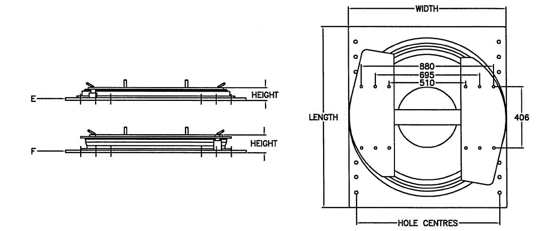
L-series = for farm carts and trailers with a speed up to 30 km/h (18m.p.h.).
N-series = for heavy farm carts and light truck trailers with a speed above 30 km/h (18 m.p.h.).
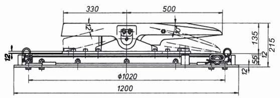
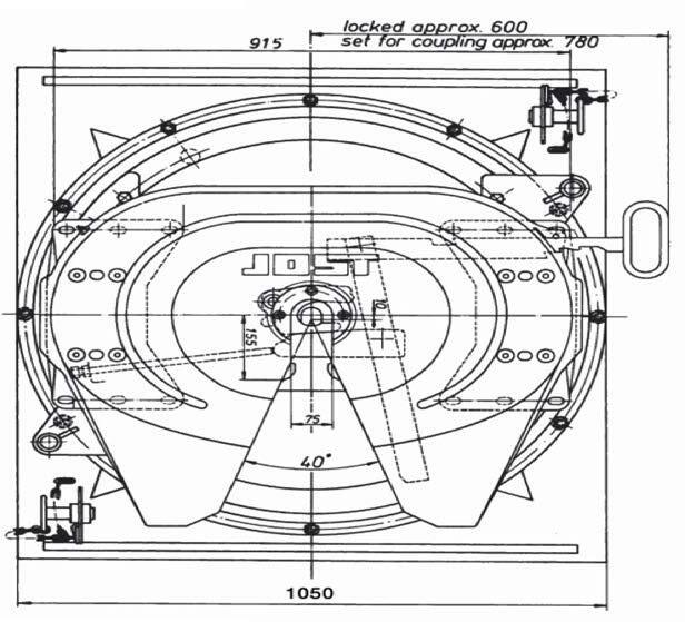
Slewing rings are supplied undrilled and primed in black for corrosion protection. The measurements are subject to our standard tolerances. For the turntables of the N series the load limits are only valid for operation on paved roads and under conditions prevailing in Europe.
The axial load can be exceeded by 30 to 50% on the turntables of the N series if the speed is below 30 km/h (18 m.p.h.).
See reverse for fitting and maintenance instructions. The right to alter specifications is reserved.
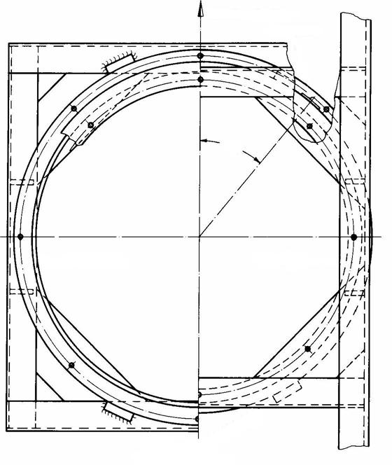
plate
Hexagon bold DIN 931 M 10 resp. M 12-8.8 tightened to 49 resp. 85 Nm or preferably according to DIN 960/961 M 10 × 1,25 resp. M 12 × 1,5 tightened to 52 resp. 89 Nm Alternative mounting with head bolt underneath, counter nut also admissible. Direction of motion
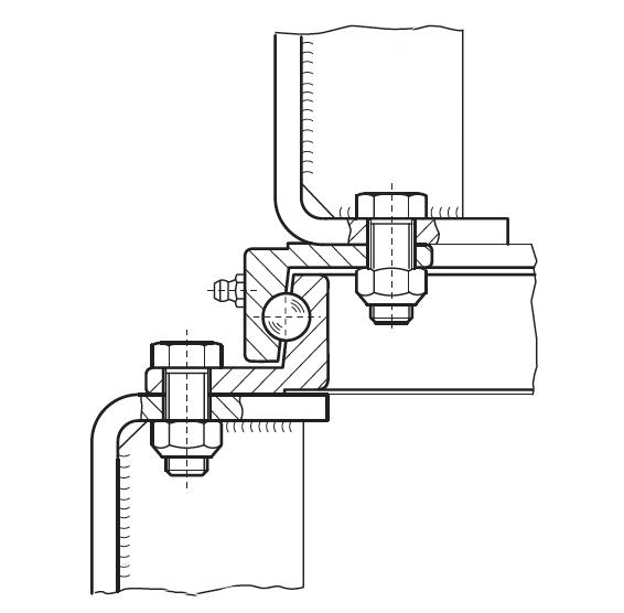
Hexagon nut DIN 980 M10 resp. M12-8 or preferably M 10 × 1,25 resp. M 12 × 1,5 X
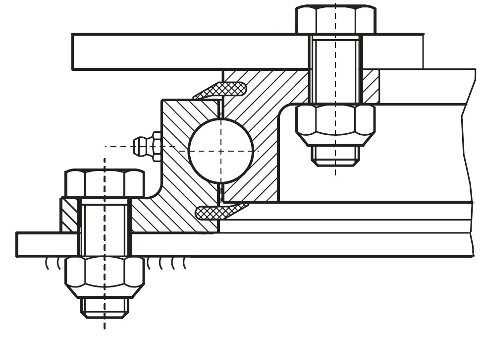
1. The ball bearing turntable must be mounted on a completely flat (max. unevenness 1mm) and horizontally and vertically rigid base with at least 50% of the circumference adequately supported. Particular attention should be paid to the support of the web section area containing the ball bearing races. Any unevenness under the flanges can be corrected with metal strips or by filling in with plastic metal.
2. Each flange must be attached with a minimum of 8 high tensile bolts grade 8.8, preferably M 10 × 1,25 (3/8 − 24) or M 12 × 1,5 (7/16−20) for sizes below 650 mm (25 5/8”) dia. 4 to 6 bolts are adequate. In case of operation under adverse conditions, we recommend the use of bolts with enlarged contact surface (such as Tensi Lock or Verbus Ripp), or to increase the number of bolts. The thickness of paint between turntable and frame should not exceed 50mm to guarantee the fit to be friction-tight.
3. To ease the shear load on the mounting bolts at least four blocks should be welded on immediately adjoining each flange. The ball bearing turntable must not be mounted by means of welding.
4. JOST turntables are lubricated with a lubricant suitable for the type of operation and the adherent operating conditions before they leave the factory, however, the turntable must be adequately re-lubricated with high quality ball bearing grease (lithium saponified, NLGI class 2) before the trailer is put into operation for the first time. The relubrication should build up a collar of grease in the gap between the 2 rings of the turntable thus preventing ingress of grit and water into the ball races.
5. The ball bearing turntable must be lubricated according to use but at least once a month with a lubricant suitable for the type of operation and the adherent operating condition (lithium saponified, NLGI class 2). While lubricating the A-frame should be turned so that the grease is evenly distributed and a collar of grease is being built up in the gap between the 2 rings. The tightness of the mounting bolts should also be checked.
6. Ball bearing turntables are subject to wear. The limit of wear is reached when there is 2,5 mm axial play. This is the case at the very latest when the air gap X = 1 mm at any point on the circumference of the turntable.
For drawbar trailers and special trailers
For drawbar trailers and special trailers
Note: SO100024 used in SO assembly Ball bearing turntables are supplied undrilled. *drilled and primed in black for corrosion protection.
The measurements are subject to our standard tolerances.
The above axial loads are applicable if the slewing ring is mounted to the front axle of the trailer with three/four axles at speeds of up to 105 km/h (65 mph).
They can be exceeded by 10% for full trailers with two axles.
In case of speeds below 30 km/h (18 mph) the axial loads can be exceeded by 20%.
If required axial loads exceed the data permitted for turntables of series HE/SO, please ask for slewing rings of series KDL900, which allow axial loads up to 250 kN.
In case of use above the steered axle and above the fifth wheel on semi-trailers with rear axle steering please enquire as to the load data giving details of the vehicle.
The load limits are only valid for operation on paved roads and under conditions prevailing in Europe.
See reverse for fitting and maintenance instruction
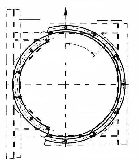
Alternative mounting with bolt head underneath counter nut also admissible Direction of motion
1. The ball bearing turntable must be mounted on a completely flat (max. unevenness 1mm) and horizontally and vertically rigid base with at least 50% of the circumference adequately supported. Particular attention must be paid to the support of the web section area containing the ball bearing races. Any unevenness under the flanges can be corrected with metal strips or by filling in with plastic material.
2. Each flange must be attached with at le ast 8 h igh tensile bolts, M 16 x 1,5 of grade 8.8. Do not drill in the area of the type plate ball insertion hole which should be at less than 30° to the direction of travel. In case of operation under adverse conditions, we recommend the use of bolts with enlarged contact surface (such as Tensi Lock or Verbus Ripp), or to increase the number of bolts from 8 to 12 per flange. This applies in particular to type HE130022 The thickness of paint between turntable and frame should not exceed 50 mm to guarantee the fit to be friction-tight.
3. To ease the shear load on the mounting bolts at least four blocks should be welded on immediately adjoining each flange. The ball bearing turntable must not be mounted by means of welding.
4. JOST ball bearing turntables are suitably lubricated before they leave the factory, Before the trailer is put into operation for the first time, however, they should be re-lubricated with a high quality lithium saponified turntable grease of NLGI class 2 through all the grease nipples. The re-lubrication should build up a collar of grease in the gap between the 2 rings of the turntable thus preventing ingress of grit and water into the ball race. If a central lubrication system is to be used the quantity of lubrication nipples should be increased (please specify when ordering) and the above mentioned grease specification observed, however NLGI consistency class min 1.
Hexagon bold DIN 931 M 16-8.8 tightened to 210 Nm, or preferably according to DIN 960/961 M 16 x 1,5 - 8.8 tightened to 225Nm
Hexagon nut DIN 980 M 16-8.8 or preferably M 16 x 1,5 - 8
5. The ball bearing turntable must be lubricated according to use but at least once a month with a high quality lithium saponified turntable grease of NLGI class 2. lubricant suitable for the type of operation and the prevailing operating conditions. While lubricating the A-frame should be turned so that the grease is evenly distributed and a collar of grease is being built up in the gap between the 2 rings. The tightness of the mounting bolts should also be checked
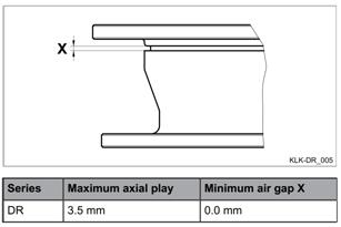
6. Ball bearing turntables are subject to wear The limit of wear is reached when there is 3,5 mm axial play. This is the case at the very latest when the air gap X = 0 mm at any point on the circumference of the turntables.
shaped profile
The measurements are subject to our standard tolerances.
Model
KDL9006W Supplied Pre-Drilled
Typical applications: Fridge Vans Stock Crate D-Value Rating*: 240kN
• Slewing rings are supplied primed for corrosion protection.
• Material C45.
• Ball race hardened.
• 8 conical lubrication nipples AM 8 × 1 according to DIN 71412.
*As tested in a JOST assembly
The below axial loads are applicable if the slewing ring is mounted to the front axle of a trailer at speeds of up to 105 km/h (65 m.p.h.). If it is to be used in self steering systems or above a fifth wheel please contact us for the maximum permissible loads by submitting construction data.
M 16 x 1,5 – 8 resp. M 16 – 8 Direction of
Welded stops above and below
1. The slewing ring must be mounted on a completely flat (max. unevenness 1mm) and rigid base with at least 50% of the circumference adequately supported. Particular attention must be paid to the support of the web section area containing the slewing ring races. Any unevenness under the flanges can be corrected with metal strips or by filling in with plastic metal.
2. Each flange must be attached with at least 12 high tensile bolts M 16 × 1,5 of at least grade 8.8. Do not drill in the area of the ball insertion hole, which should be at less than 45° to the direction of travel. The thickness of paint between slewing ring and mounting should not exceed 50 microns to guarantee the fit to be friction-tight.
3. To ease the shear load on the mounting bolts in the case of horizontal force at least 4 blocks should be welded on immediately adjoining each flange. The slewing ring must not be mounted by means of welding.
4. JOST slewing rings are initially lubricated before they leave the factory. Before they are put into operation for the first time however they must be adequately re-lubricated with ball bearing grease (lithium saponified, NLGI class 2). Whilst
Hexagon bold DIN 960
M 16 x 1,5 – 8.8 tightened to 225 Nm; alternatively M16 – 8.8, tightened to 210 Nm, according to DIN 931
Alternative mounting with head bolt underneath, counter nut also admissible.
Hexagon nut DIN 980
lubricating the slewing ring should be turned so that the grease is evenly distributed. If a central lubrication system is to be used we recommend increasing the number of grease nipples (please state on order) and using a high quality lithium saponified ball bearing grease of at least NLGI class 1.
5. The slewing ring must be lubricated according to use but at least once every 3 months or 25,000 km, using a high quality ball bearing grease (lithium saponified, NLGI CLASS 2). Whilst lubricating the A-frame should be turned so that the grease is evenly distributed.
The tightness of the mounting bolts should also be checked at regular service intervals.
6. Slewing rings are subject to wear. The limit of wear is reached when the axial play is 3.5 mm. This is at the latest the case when the distance X < 8 mm at any point on the circumference.
Wear Limits
Radial play - max. 3.0mm
Axial play - max. 2.5mm
Model
Double Row Ballrace KLK Series
Typical applications: Dairy Tankers, Tri Axle Tippers
D-Value Rating: 275kN
• Ballraces are supplied E-coated.
• 8 lubrication points enable the best possible distribution of grease.
• Lbryrinth seal.
• Supplied drilled/undrilled.
The specified axle loads for KLKDR series relate to use where the slewing ring is mounted on the front axle of a trailer with three axles and fifth wheel steering, travelling at speeds of up to 100kph (65mph). On dual-axle trailers, the specified axle load can be exceeded by 10% of 20% at speeds below 30kph (18mph).
KLKDR4100010K
KLKDR210010K
KLKDR110020
KLKDR4200010K
KLKDR4400010K
Note: The pre-drilled hole pattern on the KLKDR41AS010K is suited only for a DR assembly replacement. Other ballraces are undrilled as standard. For any special drilling requirements please contact JOST Australia.
Note: The above ratings are in accordance to ADR requirements.
The measurements are subject to our standard tolerances.
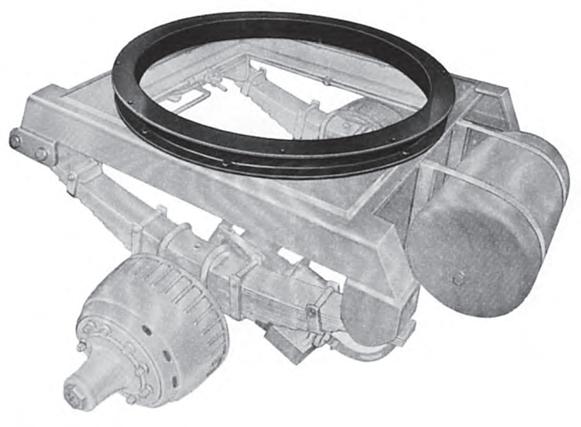
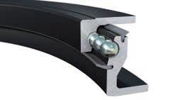
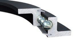
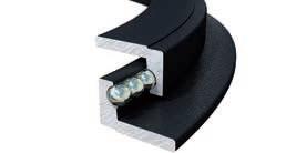
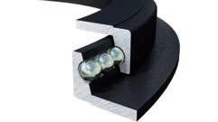
The ball bearing turntables enable the rotation of the pivot support towards the trailer frame. Thanks to the functional design, the axial loads are ideally supported and the thrust and tractive forces which occur when driving are transmitted in an optimal fashion.
The advantages at a glance:
Premium force transmissions for the highest demands
• The extra large support balls transmit the axial loads ove a wide area directly onto the vertical bar of the ring parts
• Horizontal forces in pull or push direction, as well as the moment load resulting from braking and centrifugal forces, are supported by the interplay of the two ball rows
• Lifting forces are transmitted by the smaller radial ball
• Optional fastening using splined bolts, making additional welding of thrust plates unnecessary
Durable construction with very little wear
• The use of high-strength steel ensures the greatest possible surface quality
• Cold-twisting of tracks by shrinking the ball gearing turnable reduces wear to a minimum and increases
• A robust labyrinth seal protects the tracks from dirt, even in extreme conditions
• The practiculary large grease reservior resulting from the free space between the tracks guarantees smooth running thanks to opium lubrication.
• 8 lubrication points enable the best possible distribution of grease within the tracks with just minimal rotation (+/- 20°) during lubrication.
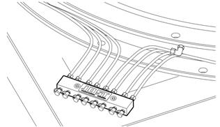
• Optionally available with pre-assembled lubrication block to ensure ideal access to the lubrication points or as preparation for connection to a central lubrication system.
Note: D-values may vary when used in conjunction with additional JOST products that have been tested and carry a CRN number. Contact your local JOST branch for further details.
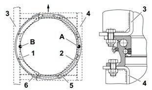
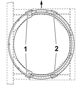
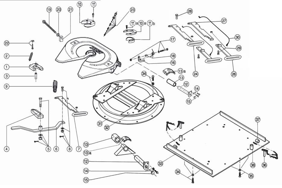
1.Upper ring
2.Lower ring
3.Chassis
4.A-frame
5.Thrust plates bottom
6.Thrust plates top
A.Position of the type plate
B.Position of the ball earing lling hole
1.Standard mounting.
The ball bearing turntable must be tted on a at (max. offset 1mm) support construction that provides torsional, longitudinal and lateral rigidity. To ensure there is an adequate transfer of force, at least 50% of the ange surfaces must be supported with weight-bearing structures. The bearing zone must be distributed evenly in and lateral to the direction of travel and be designed so that the ball bearing turntable is supported in the area of its vertical pro le bars, i.e the ball race-ways. Larger planarity deviations can be compensated with shim panels. With undrilled turntables, the following must be noted with drilling the fastening holes.
• That no drill chips or cutting uid gets into the raceway.
• That no holes are drilled in the vicinity (+/- 15mm) of the ball insertion hole or in the vicinity of the welds.
• That the type plate is placed at 90 degrees to the right of the vehicle and the ball insertion hole is placed at 90 degrees to the left of the vehicle to remove the smaller cross-sections from the area under maximum stress.
• The lubricating nipples are easily accessible.
• Free motion of the swivel movement is ensured.
Special fastening
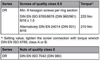
Screws of strength class 8.8 must be used for fastening. The screw connections must be secured using state of the art methods to prevent them coming loose.
Do not secure the ball-bearing turntable by welding. In general, the layer thickness of the paint build-up must be no more than 170 µm per component in the screws grip area so that a perfect friction lock is guaranteed without settling.
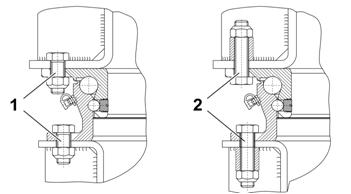
The values shown are guide values for a coefficient of friction µtot. = 0.14. Further information is available in VDI 2230. Tighten screws with a suitable tool diagonally. In case of fastening with a low number of screws or small screw size, at least the same overall stability must be achieved.
In more arduous operating conditions, we recommend installing screws with a spacer sleeve or increasing the number of screws in order to maintain the correct pre-tensioning force. With different screw connections, as shown in position (1) and (2), free movement of the turntable must be absolutely guaranteed, especially in the area of the lubricating nipples and the type plate.
When used on single axle bogie steering systems at axle loads of up to 10t, the standard hole patterns can be used as per the JOST product data sheet in combination with splined bolts for attachment to the vehicle without the use of thrust plates.If the axle load of the bogie is greater than 10t, we recommend using at least 12 securing points per ring, distributed as evenly as possible, with splined bolts.In order to ensure that the tting of the turntable or slewing ring is under as little strain as possible, a positional accuracy for the hole pattern of 0.6mm and a drilling diameter of 18 +/-0.1, should be observed.More detailed information can be found in our installation instructions for JOST splined bolts.
To relieve the thrust force on screws subject to horizontal forces, the tted ball bearing turntable must be attached to the anges with four pre-welded thrust plates and there must be no play between the components. Use the welding methods set out by the trailer’s manufacturer for this purpose. In cases of special fastenings with JOST splined bolts there are no trust plates required, if the requirements speci ed in ‘special fastening’ are met.
The JOST DR series has a permanent cathode dip coating. The CDC offers the ideal surface sealing method and therefore excellent protection against corrosion. Thanks to the evenly thin coating, it may be painted over at any time.
Fastening set KLE0000500 (16 screws M16 x 1.5 x 55 - 8.8, 16 nuts M16 x 1.5 – 10 and 8 thrust plates.
Min. 8 JOST splined bolts M16 x 55-10.9 per ring section and matching JOST nuts M16-10.9, tightening torque 300Nm. Fastening set KLE0000300 (16 splined bolts and nuts) Fastening set KLE0000400 (24 splined bolts and nuts)
Standard ball bearing turntables are supplied with light basic lubrication. Before commissioning, the turntable must be given a thorough re-lubrication over all lubricating nipples with a high quality rolling bearing grease (lithium soap, NGLI consistency class 2), with a closed bead of grease sealing the bearing clearances against the penetration of dirt and spray water. We recommend the use of JOST high performance lubricant (SKE005670000). Where a central lubricating system is used, a high quality rolling bearing (lithium soap, NLGI consistency class min. 1) should be used. At least 6 lubricating nipples should be connected.
The ball bearing turntable must be lubricated at least every 8,000 to 10,000km, or once a month, with a high quality rolling bearing grease (lithium soap, NLGI consistency class2). This is done by swivelling the bogie backwards and forwards until as closed a bead of grease as possible comes out from the entire length of the bearing clearances or sealing lips. We recommend the use of JOST high performance lubricant (SKE005670000).
• If the ball bearing turntable is used in forced steering systems, the servicing instructions of the manufacturer must be observed.
• The screw connections must be checked as part of the vehicle inspections, but no later than 50,000km, to ensure they are tightened to the prescribed tightening torque.
• Check for wear.
• Ball bearing turntables and their fastening elements, must be checked for excessive corrosion, damage or cracks.
• Only use the speci ed lubricating grease for servicing work.
• The servicing work should only be completed by trained personnel.
• Do not change the installation area de ned by the trailer’s manufacturer.
• The assembly work may only be completed by authorised specialists.
• Instructions from the trailer’s manufacturer must be observed e.g. the type of fastening and support construction.
• The installation guidelines provided by the trailer’s manufacturer must be complied with.
Technical modi cations reserved. The latest information can be found at www.jostaustralia.com.au or www.jost-world.com
Note: JOST ball races are initially lubricated before they leave the factory. Before they are put into operation for the rst t ime however they must be adequately re-lubricated with ball bearing grease.
JOST ball races – Lithium Sapon ed, NLGI class 2. (Use class 1 grease if a central lubrication system is to being used)
BPW Double Row – BPW special long life grease ECO-Li 91 Lithium Complex Grease.
The grease must not be mixed with other calcium base or sodium base lubricants.
Ball races should be lubricated at least every 25,000klm or every 3 months, or sooner depending on the application. Under extreme or arduous operating conditions greasing may be required weekly. The ball race should be rotated during greasing to ensure that the grease is distributed evenly.
The tightness of the mounting bolts should also be checked at regular service intervals.
Ball races are subject to wear. It is recommended that the ball race be replaced when the wear limits are reached.
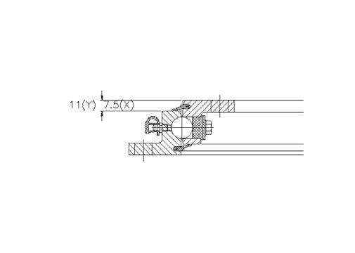
Jost KDL 900/6 Radial Play max 3.0mm – Axial Play max 3.5mm (< 01.2010)
Jost KDL
BPWDK9014
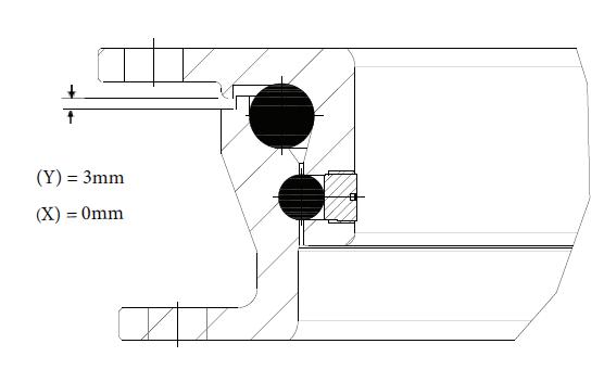
Jost KLK DR Series
900/6W Radial Play max 3.0mm – Axial Play max 3.5mm (> 01.2010)
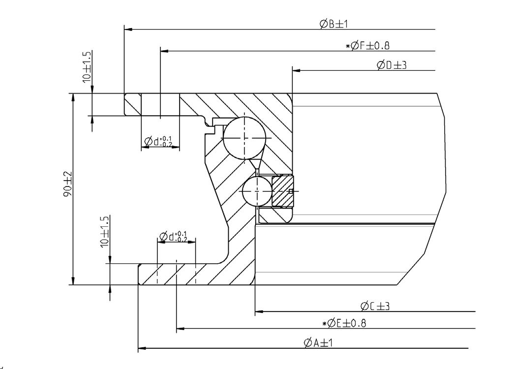
Refer to Figure 1: (Y New Ball Race 11mm) (X Measurement =7.5mm has reached wear limit)
Radial Play max 2.0mm – Axial Play max 3.0mm (< 06.2012)
Radial Play max 2.0mm – Axial Play max 3.0mm (> 06.2012)
Refer to Figure 2: (Y New Ball Race 3mm) (X Measurement = 0mm has reached wear limit)
Note: X and Y measurement pictured below refer to axial movement
KDL900 Series
KLK DR & DK9014 Series
Ball bearing turntables and slewing rings are parts for tting onto trailers and agricultural vehicles to connect the A-frame t o the trailer chassis so it can swivel. They are the products which started the success story of JOST in 1952. Today, they are used on all the world‘s roads. And not only that: They are also used in agriculture, at airports and railway stations, in mining and in a wide range of special applications, such as in TRIDEC forced steering. The ball bearing turntables are subject to constant further development, so that they impress with their innovative bene ts and proven quality time and again.
E-coating
• Premium corrosion protection
• Additional top coat on request
Verified safety
• Tested in accordance with ECE R55
• Environmental management in accordance with ISO 14001
• Quality management in accordance with ISO/TS 16949
Weight advantage
• Up to 10 kg lighter than comparable products
Splined bolt
• A ssembl y ki t wi t h s p ecia l s cr ews, mak ing use o f a d di t ional welded t hrust plates unnecessary
Ite m n umbe r KLE 0 00030 0 (1 6 pieces) It em num b er K LE 0 00040 0 (2 4 pieces)
Mounting kit KLE0000500
ItemDescription per kit
01Hexagon screw M16x1,5x55 16
02Hexagon nut M16x1,5 16
03Stop block 8
Central lubrication manifold
•M ake s l ubricatio n ea sier
•M ake s con nectio n to central lubrication system easie r Item num b er K LE000020 0
High performance lubricant
•J OST hi g h pe rformance lu b rican t for in itial g reasin g or fo ll o w-u p lu b ricatio n in a p ractica l refi ll set It em num b er SK E0 056 70000
Low maintenance
• Low maintenance version for HE and KDL available
Ball bearing turntables KLKHE and SO
E-coated
Standard or low maintenance (HE series)
Drilled or undrilled
Lubrication manifold (optional)
Splined bolts (optional)
E-coated
Low maintenance
Drilled or undrilled
Hardened bearings
Lubrication manifold (optional)
Splined bolts (optional)
Customer-specific drilling patterns
• Even in small batch sizes
Ball bearing turntables KLKL and N
• E-coated
• Undrilled
• L series: Agricultural trailers and transportation devices up to 30 km/h
• N series: Heavy agricultural trailers and light truck trailers over 30 km/h
Ball bearing turntables KLKND
• E-coated
• Drilled or undrilled
• Lubrication manifold (optional)
maintenance
The application of ball bearing turntables and slewing rings depends on the permissible axial load. JOST ball bearing turntables and slewing rings cover an axial load range of between 7.5 and 250 kN.
All load data for the KDL, HE, SO, ND, L and N series apply for operation in pivot support steering systems on paved roads and under the transport conditions common in Central Europe.
JOST standard ball bearing turntables are supplied with a thin base coating of lubricant. Before it is used for the rst time the ball bearing turntable must be lubricated thoroughly. See JOST installation and operating instructions.
Connection to the central vehicle lubrication system is possible (grease is essential, rather than oil).
The low-maintenance versions of ball bearing turntables and slewing rings mean they do not have to be maintained for up to three years or 300,000 km. After this period they must be serviced in the same way as standard turntables. The low-maintenance models are distinguished by a green type plate and by the letter “W” at the end of the item number. Maintenance conditions differ when tted to steered semi-trailers or in the case of heavy conditions of use. The maximum storage period for maintenance-free ball bearing turntables and slewing rings is three years.

Refer to Jost website www.jostaustralia.com.au for further details and instructional videos.
1
2
Failure to ensure that trailer rubbing plate is set below the fifthwheel plate when coupling up could result in loss of your trailer or damage to your truck or trailer.
Regardless of whether you have air or spring suspension, ALWAYS follow the coupling CODE to ensure the king pin is securely engaged with the fifthwheel. This following coupling CODE is issued by JOST Australia Pty Ltd.
The fifthwheel must be angled down to the rear of the truck and the mechanism in the pre-set position.
Ensure that the trailer rubbing plate is below the height of the fifthwheel plate (refer Diagrams 1 and 2).
Reverse the truck slowly under the trailer, aligning the king pin with the centre of the fifthwheel.
Continue reversing until the mechanism locks and secures the king pin.
Pull forward against the trailer brakes to ensure engagement of the king pin in the fifthwheel.
Visually check to see that there is no gap between the fifthwheel plate and trailer rubbing plate and that the king pin is secured correctly within the fifthwheel mechanism.
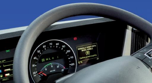
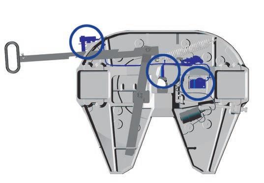
Finally, ensure that the automatic secondary locking device is engaged (as per Diagram 3). If it is not engaged, the whole coupling up procedure must be repeated.
Note: Pending the fifthwheel model, coupling code may vary.
Diagram 3
Failure to read, understand and follow the important information contained above may result in a hazardous condition or cause a hazardous condition to develop.
ensure that you get a when coupling!
1
2
Failure to ensure that the trailer rubbing plate is set level with the fifthwheel plate when coupling up, could result in loss of your trailer or damage to your truck or trailer.
Regardless of whether you have air or spring suspension, ALWAYS follow the coupling CODE to ensure the king pin is securely engaged with the fifthwheel. This following coupling CODE is issued by JOST Australia Pty Ltd.
The fifthwheel must be angled down to the rear of the truck and the mechanism in the pre-set position.
Ensure that the trailer rubbing plate is level with the height of the fifthwheel plate (refer Diagrams 1 and 2).
Reverse the truck slowly under the trailer, aligning the king pin with the centre of the fifthwheel.
Continue reversing until the mechanism locks and secures the king pin.
Pull forward against the trailer brakes to ensure engagement of the king pin in the fifthwheel.
Visually check to see that there is no gap between the fifthwheel plate and the trailer rubbing plate and that the king pin is secured correctly within the fifthwheel mechanism.
Finally, ensure that the automatic secondary locking device is engaged (as per Diagram 3). If it is not engaged, the whole coupling up procedure must be repeated.
Diagram 3
Failure to read, understand and follow the important information contained above may result in a hazardous condition or cause a hazardous condition to develop.
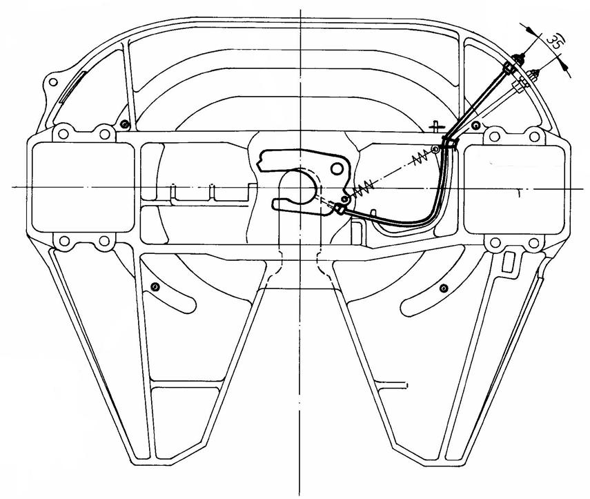
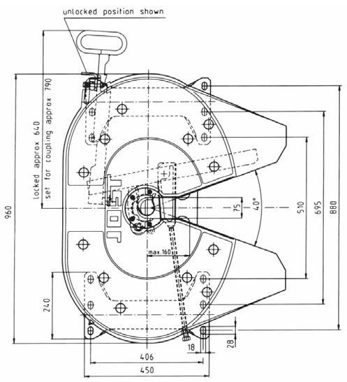
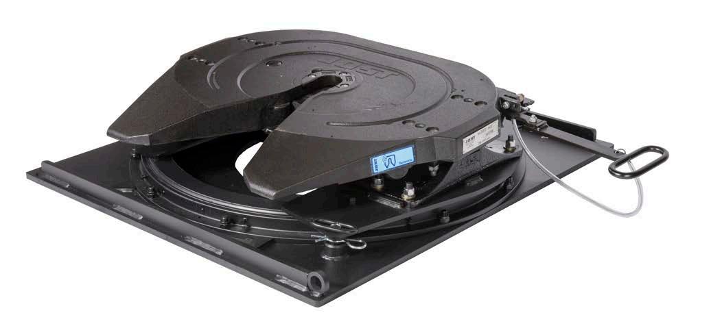
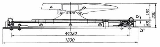
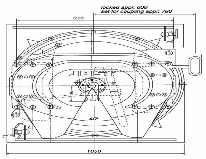
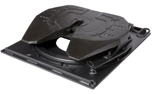
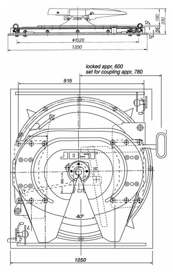
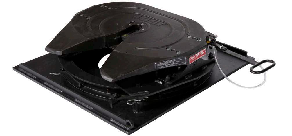
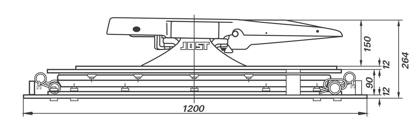
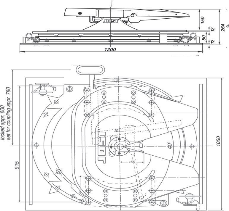
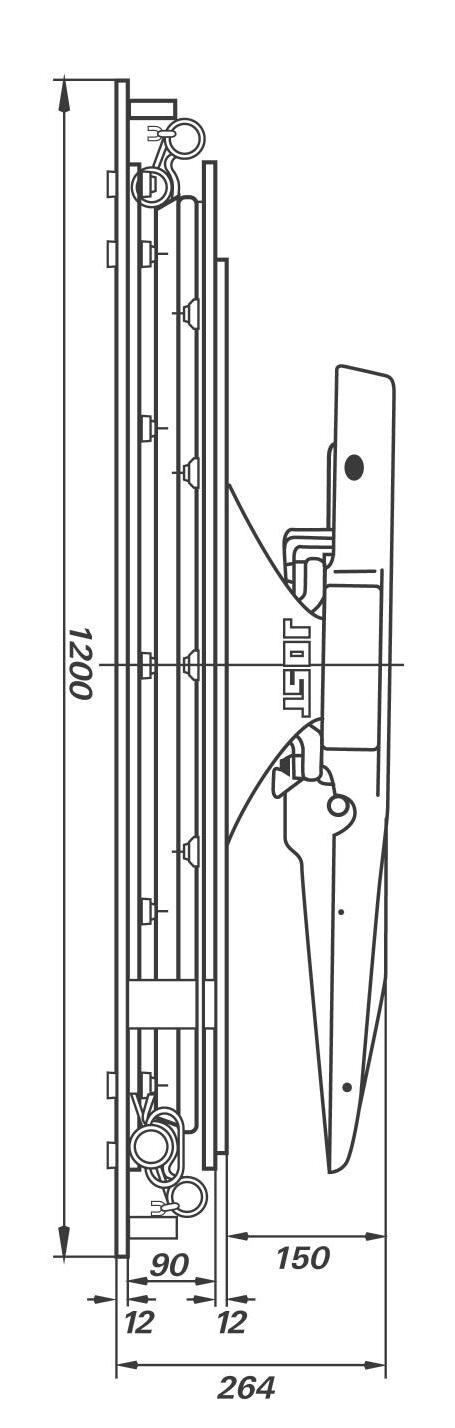
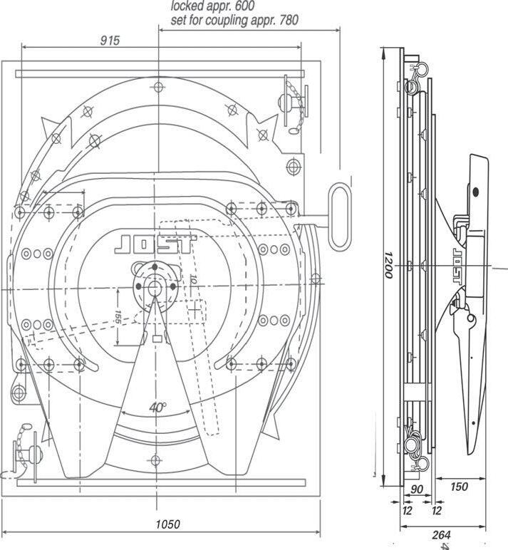
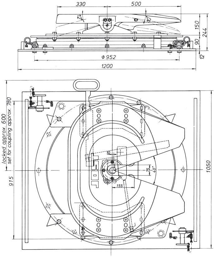
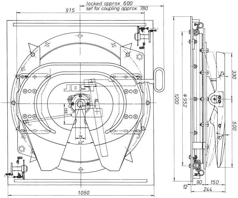
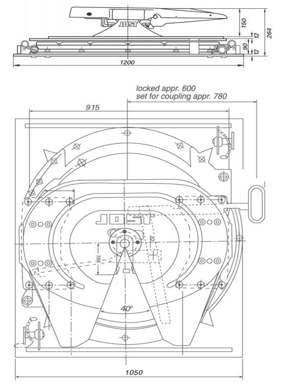
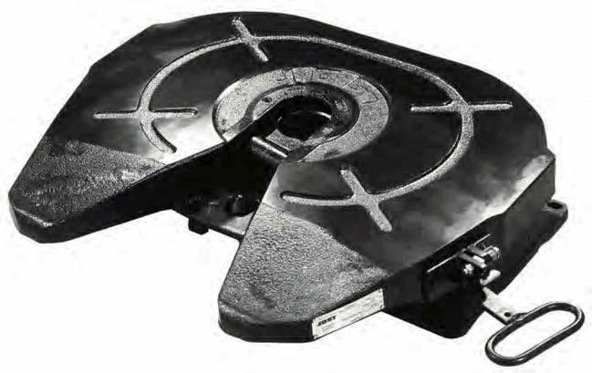
Locked with spring latch closed
• Automatic setting to couple up
• Fully adjustable wear
• Easy maintenance
Set for coupling
Type of mounting
E=
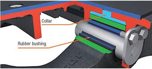
Pivot bearing mounting
Slack and maintenance free.
Oil and grease resistant
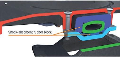
C = Rubber mounting
Shock absorbing by large rubber pads.
Slack and maintenance free. Oil and grease resistant
Selection criteria, maintenance, mounting instructions and user information for the top plate liner
The fifth wheel must be angled down to the rear of the truck and the mechanism in the present condition. Ensure that the trailer rubbing plate is level with the height of the fifth wheel plate. Reverse the truck slowly under the trailer aligning the king pin with the centre of the fifth wheel.
Continue reversing until the mechanism locks and secures the king pin. Pull forward against the trailer brakes to ensure engagement of the king pin in the coupling.
Visually check to see that there is no gap between the fifth wheel plate and the trailer rubbing plate and that the king pin is secured correctly within the fifth wheel mechanism.
Ensure lock catch is secured in the locked position.
Selection Criteria
The main characteristics of the JOST low maintenance fifth wheel coupling JSK37 are there excellent sliding properties (equivalent to a well lubricated fifth wheel) and their long life.
The fifth wheel was designed in particular for articulated vehicles with high mileage which are rarely uncoupled and run for long periods between services, e.g. tankers and tilts.
This high quality, low maintenance fifth wheel will offer you a long life span if you
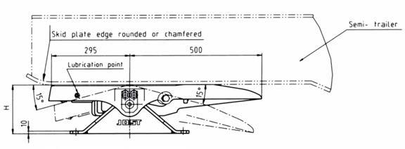
• Couple up carefully: the fifth wheel should be at the same height as the skid plate (air suspension vehicles are advantageous)
• Make sure that the skid plate resp. guide rails to the skid plate are the correct size. They should have no sharp edges, steps or welding seams in the coupling up area.
• Ensure a flat, smooth surface of the skid plate and contact area.
• Grease the skid plate lightly to protect it from corrosion. The liner is not adversely affected by grease.
if these points are not observed the liner may be damaged.
Articulated vehicles with more complex load requirements (e.g. on building sites) and/or semi-trailers with rigid chassis (e.g. tankers) are liable to increase wear on the liner.
The liner is bolted onto the fifth wheel and can be easily replaced.
Lubrication of the liner is not necessary.
The fifthwheel has only one lubrication point for the lock jaw
Uncouple at the latest every 50,000 Km or six months, depending on usage. Clean the fifth wheel with liner and the skid plate. Check the liner for damage and wear. Lubricate the lock jaw and king pin with high pressure grease (EP) with MoS2 or graphite additive (e.g. L21M,Esso universal grease M or Shell Retinax AM).
The grease nipple on the edge of the fifth wheel plate is for lubricating the lock jaw and king pin between service.
The life expectancy of the lock jaw and king pin depend on effective lubrication before being put into service and after every cleaning operation.
For further information please refer to the JOST repair instruction booklet.
Models JSK37 Series
Replacement lock jaw
See JOST repair instructions page 9 resp.14
Thread M 8 x 1 for conical grease
nipple BM 8 x 1 DIN 71412 or cylindrical screw coupling M 8 x 1 with flexible tubing
Lubrication tubing, complete
The drawing shows JSK37 C-Z
The fifth wheels JSK37CZ and JSK37E Series are supplied with additional lubrication for the lock jaw and the king pin.
In order to connect the fifth wheels to the central lubrication system of the prime mover it is necessary to replace the 4 grease nipples under the fifth wheel plate and the 2 at the side with suitable screw couplings and connect them to flexible tubing, which is in turn joined up to a distributor unit compatible with the respective central lubrication system.
As a lubricant we recommend grease or liquid grease. Fifth wheels with central lubrication should be thoroughly cleaned and inspected for wear, damage and correct functioning at least once a year, or at the latest after 50,000 km, and repaired if necessary. Before coupling up again the fifth wheel and the king pin should be manually lubricated with high pressure grease (EP) with MoS2 or graphite additive.
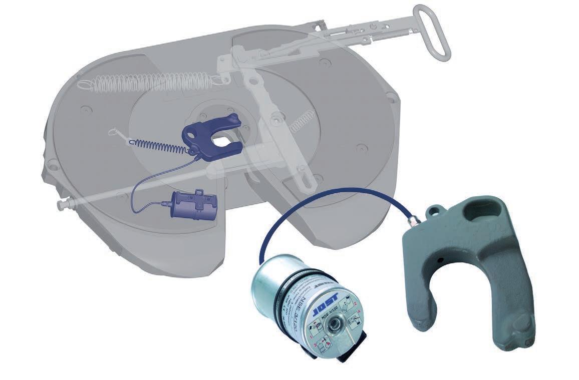
Integrated cartridge, protected under the fifth wheel plate. 3 year life span
The special multi-stage thermal coating on the jaws makes its surface highly durable.
Guaranteed safe and automatic for 3 years
JOST, the market leader in the area of couplings for trucks and trailers, remains on it’s innovative course. The new development LubeTronic saves time and money and simplifies the day-to-day life of drivers and freight forwarding companies.
Always lubricates safely
• The special coating on the lock jaw makes the surface extremely durable. This allows the lock jaw to be operated with a minimal amount of lubricant.
• Excellant emargency running properties allow the coating to handle short-term operating even without lubricant.
• Outstanding lubricant qualities thanks to novel lubricants from high-performance grease and continuous lubrication.
• Temperature range: -20°C to +70°C
• Electronic dose dispensing reduces both costs and enviromental impact
• Completely sealed and immersion tested (IP 68)
Simple maintenance
• LubeTronic is easy to mount
• Self-regulating system with electronic monitoring signal on the cartridge
• Guaranteed 3 year life span
• Maintenance time savings
• Potential upgrading of all low-maintenance couplings
• Very light and compact
• With shockproof metal bracket
• Not recommended for usage in the construction industry
• Repair kit (complete) with cartridge: Order No. SKE004070000
JOST, the market leader in the area of couplings for trucks and trailers, remains on it’s innovative course. The new development LubeTronic saves time and money and simplifies the day-to-day life of drivers and freight forwarding companies.
The lock of the fifth wheel holds the king pin firmly in place; it used to be one of the last maintenance-intensive elements in the system. LubeTronic allows this system to run practically maintenance-free for three whole years. The grease is discharged in a electronically controlled manner; the lock and king pin are always optimally lubricated. JOST guarantees automatic and safe operation of the LubeTronic for three years. The lubrication cartridges discharges it’s lubricant in a constant, uniform manner over a wide temperature range from -20 to +70 degrees Celsius and the entire system has been underwater-tested according to IP 68.
The LubeTronic retrofit kit includes a specially coated lock, which, together with the electronically regulated lubrication cartridge, is a system patented by JOST. The coating makes the surface of the lock particularly resistive and durable, so that even minimal quantities of the lubricating grease are sufficient. This is efficient and eco-friendly at the same time. The coating is so efficient that it even allows running without lubricant for short periods, although this is not recommended!
The lock holds the king pin and with it, the entire support system, coupled firmly with the traction engine. So far, regular lubrication by hand or by means of an expensive central lubrication was required, because the lock and king pin wear quickly without lubrication and have to be replaced. The traditional lubrication aids - which are mostly lubricating cartridges operated with overpressure - discharge grease smoothly and uniformly only within a narrow temperature range. All the maintenance procedures for the fifth wheel, which are not only uncomfortable and time-consuming, but above all, relevant for safety, are rendered redundant by LubeTronic.
Pressed Steel
Mounting must be carried out in accordance with our instructions.
Application: General Freight Tipper work
For use with single trailers and B Double (not Road Train)
D-value 152 kN
Approval Number E1 55R-01 0301 Weight approx.
(bolt on feet) (for 150mm height)
Available with Fabricated-weld on Pedestals upon request.
Bolt on Pedestals 185 SK929440 1 20a Fabricated Pedestals 130 SK2920130 1 20b Fabricated Pedestals 150 SK2920150 1
Fabricated Pedestals 170 SK2920170 1
Pedestals 185 SK2920185 1
Fabricated Pedestals 195 SK2920195 1
205 SK2920205 1
215 SK2920215 1
*Note 300mm non weldable pedestals
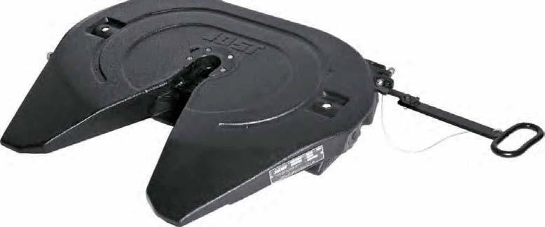
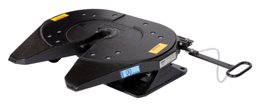
Applications: Tanker General freight Fridge van B-double Road train
The fifth wheel comes standard with bolt on/weld on feet.
The fifth wheel coupling can be linked to the central lubrication system of the prime mover.
Lock jaw and wear ring can be replaced without difficulty in a few minutes with the fifth wheel still in position.
Shock absorbing large rubber pads. Oil and grease resistant.
Mounting must be carried out in accordance with our instructions.
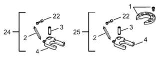
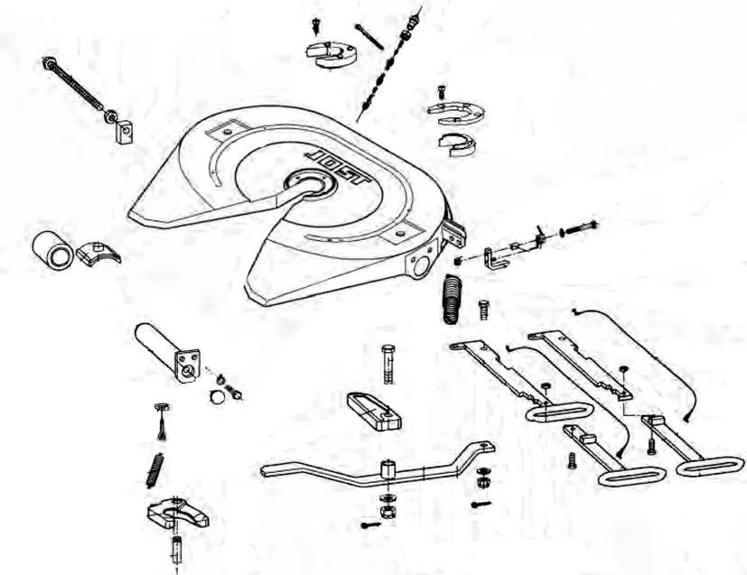
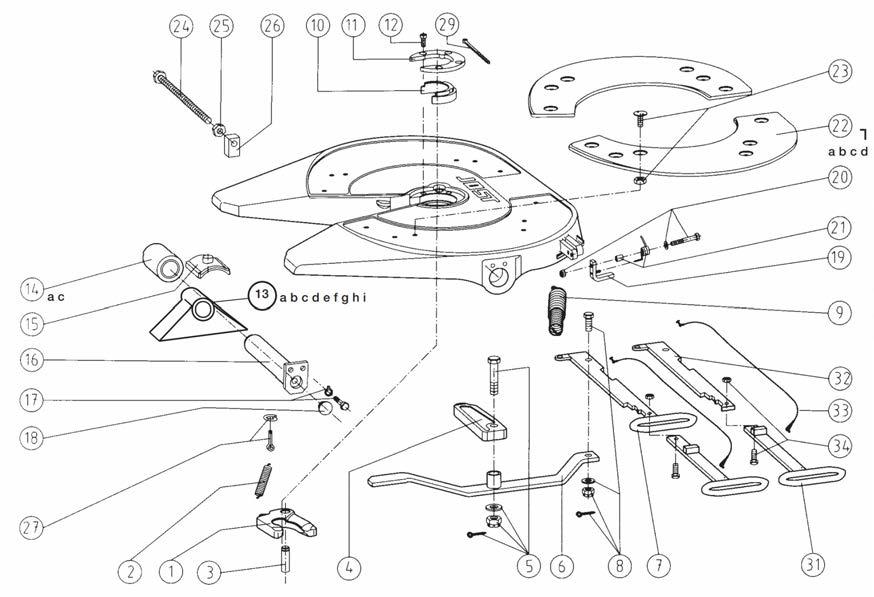
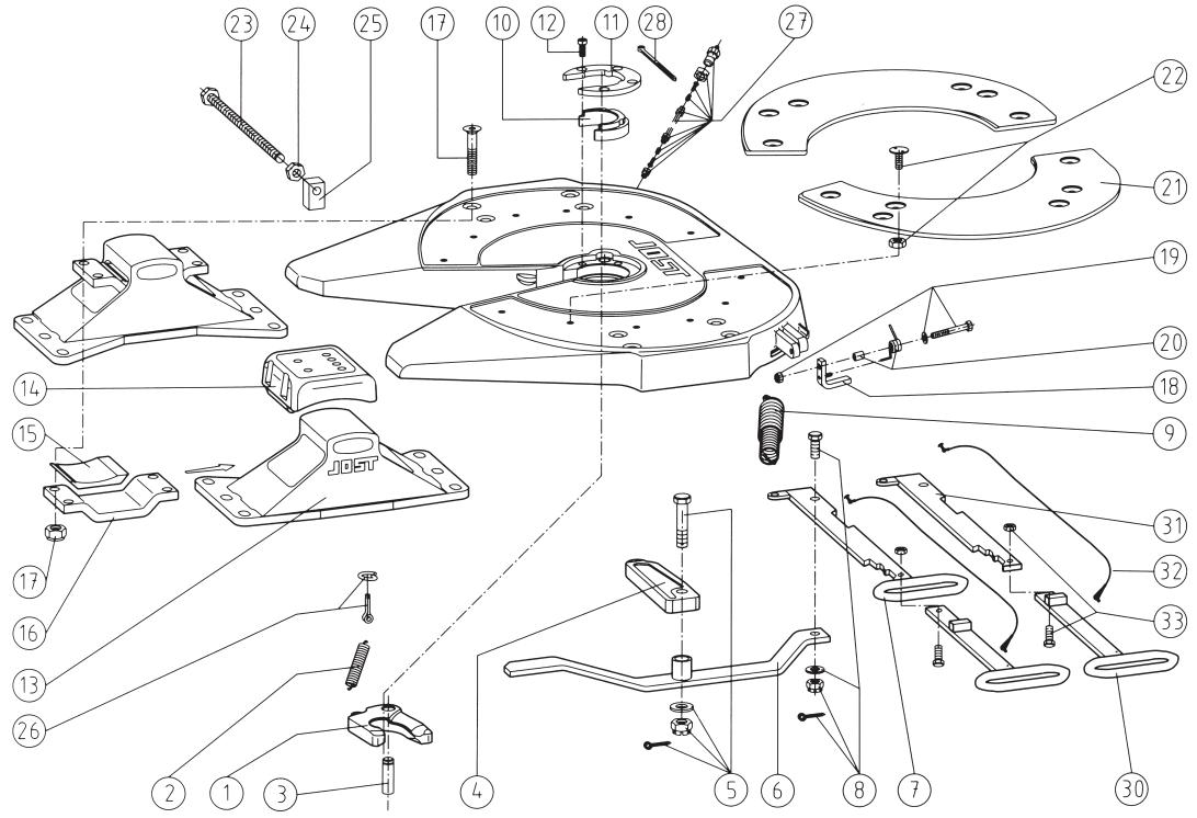
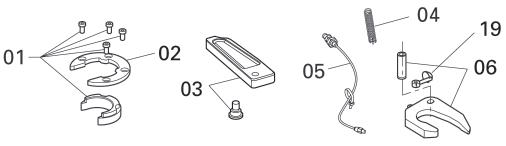
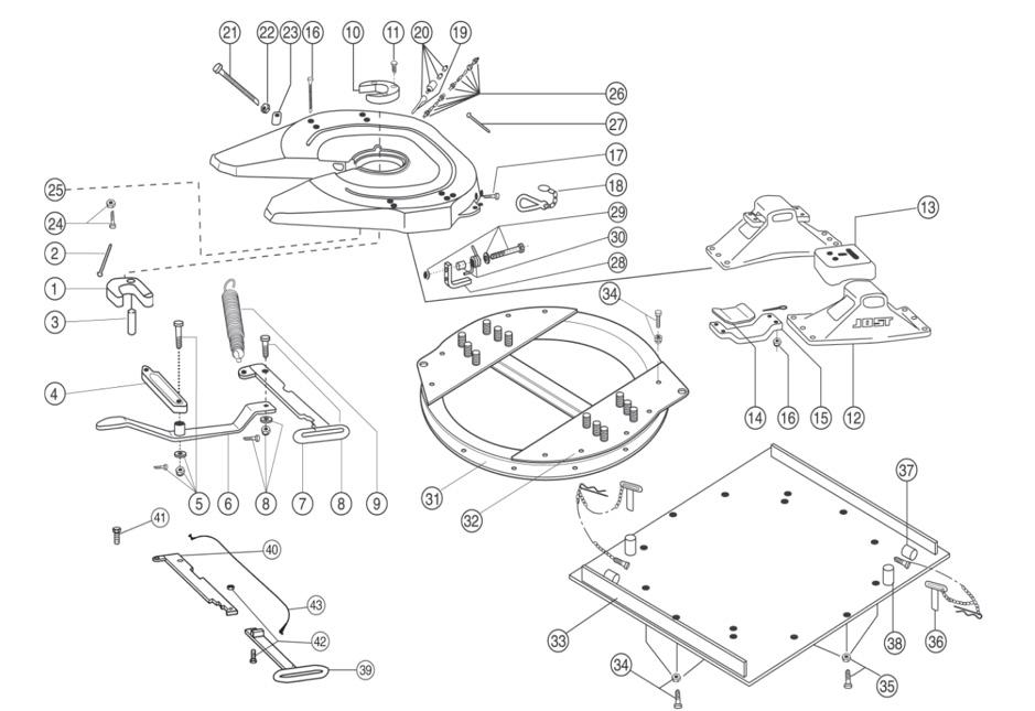
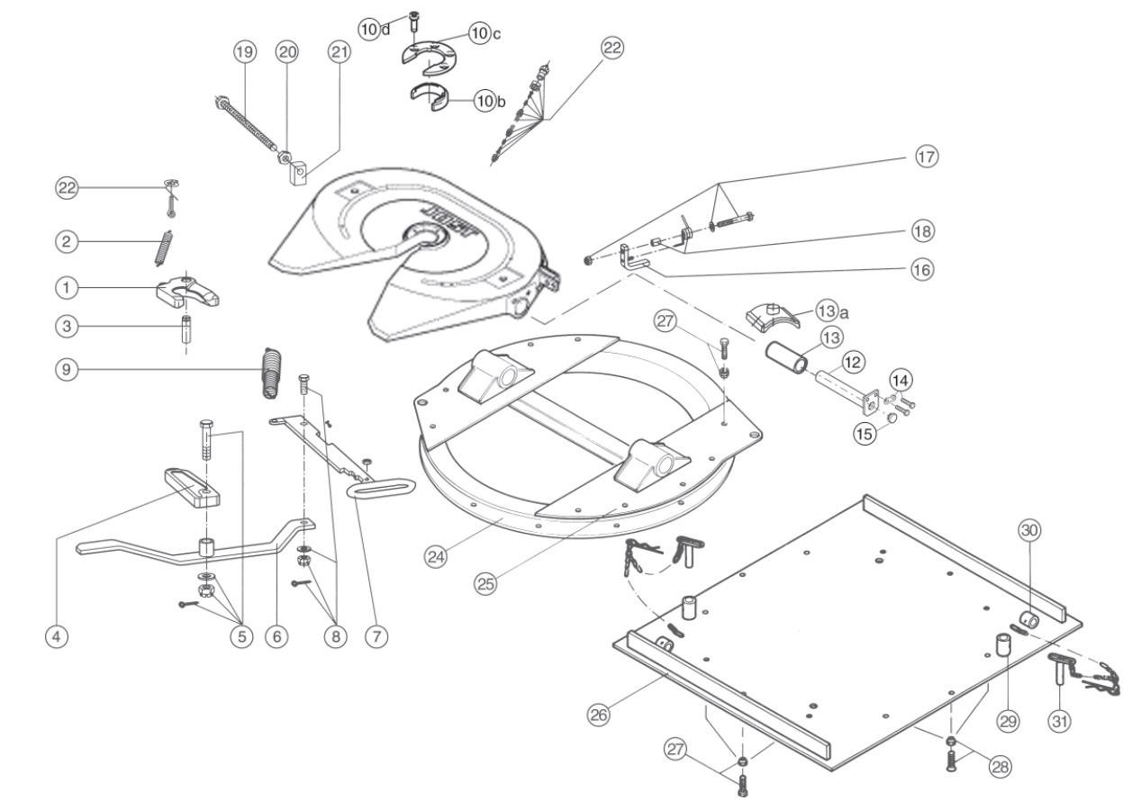
Fig. Description Part No.
01 Lock jaw
02 Lock jaw spring
03 Pivot for lock jaw, compl.
04 Locking bar
05 Locking bar bolt, compl.
06 Lever
07 Operating handle
08 Socket head bolt
09 Double tension spring
10 Wearing ring
11 Head bolt
SK1489Z
SK847
SK210667
SK320506
SK322101
SK310518
SK310515
SK1513
SK310520
SK210519
SK212107
12b Pedestal (150 mm) Bolt on\Weld on SK210402X
12c Pedestal (170 mm) Bolt on\Weld on SK210421X
12a Pedestal (185 mm) Bolt on\Weld on SK210401X
12d Pedestal (220 mm) Bolt on\Weld on SK210418X
12e Pedestal (250 mm) Bolt on\Weld on SK210414X
12f Pedestal (300 mm) Non Weldable
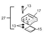
13 Upper rubber cushion
14 Lower rubber cushion
15 Mounting bracket
Fig.
01, 02, 03, 10, 11
02, 03
01, 02, 03, 08, 10, 11, 18,
13, 14, 16
28, 29, 30
SK210420
SK1259
SK210525
SK1372 Fig. Description
No. 16 Socket head bolt, compl. with nut
Spring hook Pre 1996
Lubrication fitting
SK212115
SK1974
SK1436
SK212178
SK320507
SK312111
SK312152
SK3105115
SK1513
SK242150
SK352102
*Note 300mm non weldable pedestals
Applications: Stock crate Fridge van Tanker B-double Road train
Sturdier fifth wheel coupling plate, with central relief to avoid load concentration on the coupling system. A heavy-duty fifth wheel coupling for operation in arduous conditions.
Pedestals fixed by 6 bolts. Hole areas have been reinforced.
Lock jaw and wear ring can be replaced without difficulty in a few minutes with the fifth wheel still in position. Mounting must be carried out in accordance with our mounting instruction.
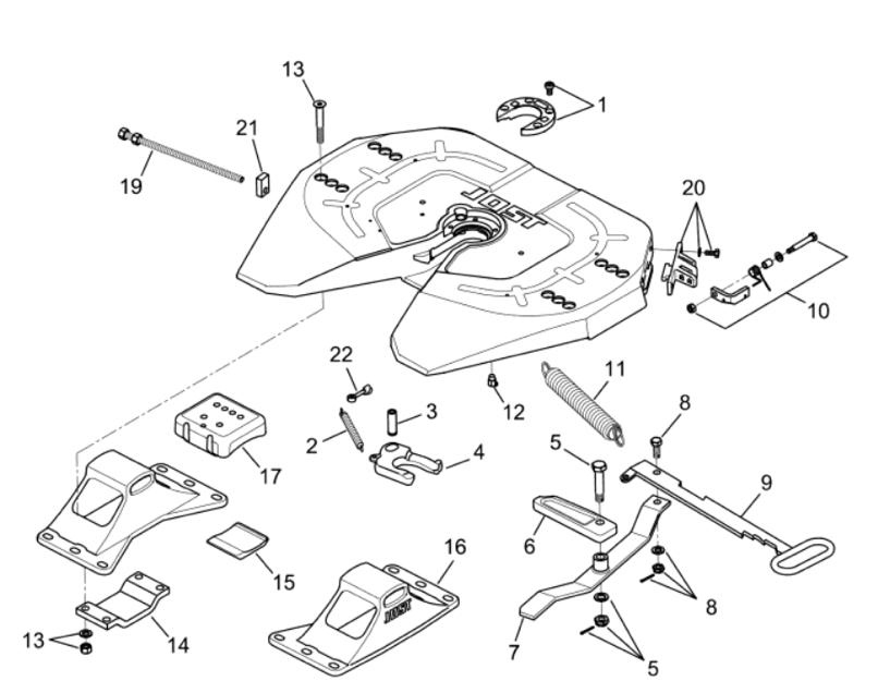
Fig. Description
01 Wearing ring and bolts
02 Lock jaw spring
QR00269J00
SK847 03 Pivot
04 Locking jaw
05 Bolt (complete)
06 Locking bolt
07 Lever with bushing
SK210667
SK1489Z
SK322101
SK320506
SK310518
SK1513
SK310515
SK312152KIT
14 Mounting bracket
15 Lower rubber cushion
QR00215J01
SK21025
16a Pedestal (150mm) SK210402X
16b Pedestal (170mm)
SK210421X
16c Pedestal (185mm) SK210401X
16d Pedestal (220mm) SK210418X
16e Pedestal (250mm) SK210414X
16f Pedestal (300mm)
17 Upper Rubber Cushion
19 Adjustment screw
20 Guide latch complete security
SK210420
SK1259
AD01148B80
QR00270J00
21 Guide with thread SK320507
22 Pin with eyelet SK212204
SK212169CX
The right to alter specifications is reserved.
Applications: Highway Work Tipper Work
Lock jaw and wear ring can be replaced without difficulty in a few minutes with the fifth wheel still in position. Available with extended operating handle (240mm) on demand.
Mounting must be carried out in accordance with our instructions.
Mounting hole pattern in accordance with DIN standard 74081 and ISO standard 3842. Suitable for all types of rear axle steering systems.
CTA-036821
CTA-036821
13e
13f
The right to alter specifications is reserved.
Applications: Highway work Tipper Work
Low maintenance fifth wheel coupling:
• maintenance free top plate
• maintenance free rubber cushioned pivot bearings
• maintenance free wear ring
• only one remaining grease point the lock jaw (little grease required)
Lock jaw and wear ring can be replaced without difficulty in a few minutes with the fifth wheel still in position.
Available with extended operating handle (240mm) on demand.
Mounting must be carried out in accordance with our instructions.
Mounting hole pattern in accordance with DIN standard 74081 and ISO standard 3842. Suitable for all types of rear axle
SK310595
SK310405
SK312128
JS110112
SK312152
SK352103
SK312159
SK3105/130L
SK3105/130R
bolt (new style) SKT 001006000
screw SK310597
13a Cast Pedestals 6 inch (155.8mm) SKE-6IN-W
13b Cast Pedestals 7 inch (181.2mm) SKE-7IN-W
13c Cast Pedestals 8 inch (206.6mm) SKE-8IN-W
13d Cast Pedestals 9 inch (232.0mm) SKE-9IN-W
13e Bolt on Pedestals 150mm
13f Bolt on Pedestals 170mm
13g Bolt on Pedestals 185mm
SK2904/42
SK2904/41E
SK2904/40
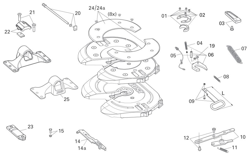
Fig. Repair Kits Part No.
1, 2, 3 Repair kit for locking device SK322152Z
1, 2, 3, 8, 10, 12, 28 Repair kit for locking device SK3121060Z
10, 11, 12 Repair kit for wearing ring SK310494
SK212178
bolt, compl. SK212204
tubing, compl. SK310802
SK312113
handle, grip SK3105113
Latch cord, compl. SK352102
Socket head bolt, compl. SK242150
Lubetronic grease cartridge SKE003110310
Fig.Repair Kits Part No.
22aSteel Inserts 6 bolt LH
SK4001L 22aSteel Inserts 6 bolt RH SK4001R
22Steel Inserts (6 bolt) kit SK4000
14, 15, 16, 17, 18 22,23 Repair kit for top plate liner 10mm (6 bolt) kit
Repair kit for bearing SK3121061
19, 20, 21 Repair kit for spring latch SK312152 Kit
SK3106007
Handle extension, compl. SK3121063
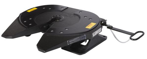
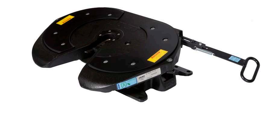
Applications: Tanker
General freight Stock crate Fridge van B-double Road train
Low maintenance fifth wheel coupling:
• maintenance free top plate
• maintenance free rubber cushioned pivot bearings
• maintenance free wearing ring
• only one remaining grease point the lock jaw (little grease required)
Lock jaw and wearing ring can be replaced without difficulty in a few minutes with the fifth wheel still in position.
Available with extended operating handle (240mm) on demand.
Mounting must be carried out in accordance with our instructions.
Mounting hole pattern in accordance with DIN standard 74081 and ISO standard 3842.
*Note 300mm non weldable pedestals
Lockjaw
Operatinghandle(standard)
Pedestal(150mm) bolt on\weldable
Pedestal(170mm) bolton\weldable
Pedestal(185mm) bolt on\weldable
Pedestal (220mm) bolt on \weldable
Pedestal(250mm) bolton\weldable
Pedestal(300mm)bolton
Upperrubbercushion
SK3105-93 SK3121-55
SK2104-02X SK2104-21X SK2104-01X SK 2104-18X SK2104-14X SK2104-20 SK1259
13a Pedestal (150mm) bolt on\weldable SK210402X
Lowerrubbercushion
13b Pedestal (170mm) bolt on\weldable SK210421X
SK2105-25 SK1372
13c Pedestal (185mm) bolt on\weldable SK210401X
13d
Pedestal (220mm) bolt on\weldable SK210418X
Repairkitforlockingdevice
SK3221-52Z
13e Pedestal (250mm) bolt on\weldable SK210414X
13f
Repairkitforwearingring 10,11,12
Repairkitforbearing 14,15,17
SK3105-94
SK2121-69Z
Pedestal (300mm) bolt on SK210420
Repairkitforspringlatch 18,19,20
Repairkitforspringlatch 19,20,21
SK3121-52
SK3121-59
SK Repair kit for top plateliner (4 bolt)
Therighttoalterspeci cationsisreserved
JostAustraliaPty.Ltd.
SK2121-15
Countersunkbolt,compl. 8 18 SK3121-52 Latch 19 SK3521-03 Boltforspringlatch 20 SK3121-59 Springnoosewithspacer 21a
SK Topplateliner,righthand(6bolt) 3105-12910R 21b
SK Topplateliner,lefthand(6bolt) 3105-12910L 21c
SK3105/130L Topplateliner,righthand(newstyle) 21d SK3105/130R Topplateliner,lefthand(newstyle) 22a SK3121-062 Countersunkbolt,compl. 22bHexalobularbolt(newstyleboltonly) 12 SKT001006000
Adjustingscrew
Eyebolt,compl.
Lubricationtubing,compl.
SK3105-97
SK2121-78 Hexagonnut
SK3205-07
SK2122-04
SK352103
only) SKT 001006000
SK3108-02
SK3121-13 Tubingclamp
SK3105-113 Extendedhandle,grip
SK3105-115 Extendedhandle,lowerpart
SK2421-50 Socketheadbolt,compl. PartNo.
nut SK212178
SK320507
bolt, compl. SK212204
SK3521-02 Latchcord,compl.
tubing, compl. SK310802
1,2,3 SK Repairkit for top plateliner (6 bolt)3106-007
SK4000 SteelInsertsKit8mm(6bolt)
SteelInserts6boltLH
SteelInserts6boltRH Kit
SK4001L/8mm
SK4001R/8mm
Handleextension,compl. SK3121-063 21,22
Repairkitforspringlatch
SK3121-52Kit
SK312113
SK3105113
Repair Kits
Sydney (02)98388100
Brisbane (07)32725777 TollFreeSydney1800811487
Melbourne (03)93609001 www.jostaustralia.com.au
Fig. Repair Kits
01, 02, 03 Repair kit for locking device
Part No.
SK322152Z
10, 11, 12 Repair kit for wearing ring SK310594 14, 15, 17 Repair kit for bearing SK212169Z 18, 19, 20 Repair kit for spring latch SK312152 19, 20, 21 Repair kit for spring latch Kit SK312159 21, 22 Repair kit for top plate liner (6 bolt) SK3106007
The right to alter specifications is reserved
Perth (08)93554137 8/08 17
Fig. Repair Kits
Part No. 21, 22a Steel Inserts Kit 8mm (6 bolt) SK4000 22 Steel Inserts 6 bolt LH SK4001L 22 Steel Inserts 6 bolt RH SK4001R 30, 32, 33 Handle extension, compl. SK3121063 18, 19, 20 Repair kit for spring latch SK312152 Kit
The fifth wheel coupling complies with the following directives/ standards: 94/20/ EC - Class G50, DIN 74081, ISO 3842. Suitable for mounting 2” king pins (50) as per 94/20/EC, DIN 74085, ISO 337 and steering wedges as per 94/20/EC, DIN 74085, AS/NZS 4968-1:2003.
Repair and retrofit kits
Features
• Safety solution with remote dash display
• Road-Train rated – 190kN
• JSK37C 3 point sensor with dash display
• Connections sensor, king pin sensor and coupling height sensor.
• Integrated dash display available (truck specific)
• Extended handle for easy operation
• Optional lubetronic technology.
• Greaseable and greaseless options available
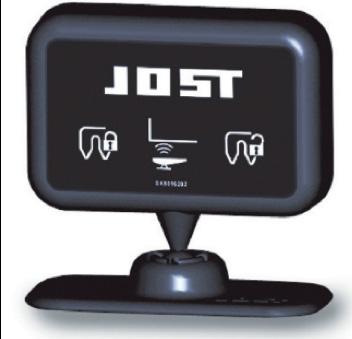
A = sensor for connection status
B = sensor for king pin
C = sensor for coupling height

Advantages at a glance
• Sensors provide best possible safety during the coupling process
• Increased safety even in poor visibility
• A remote display processes the signal and displays it in the driver’s cab
SparepartsJSK36+37
• A sensor permanently monitors the connection status
• A second sensor controls the position of the king pin
• An additional third sensor monitors the contact locking position and displays it in the driver’s cab.
• The sensors are located in protected zones on non-moving parts
• Electromagnetical compatibility according to highest standards
• Also suitable for use in the transport of dangerous goods (ADR)
ItemDescription
with07
03 Retaining plate for trailer sensor with 08
1 03Retainingplatefortrailersensor with08 SKE003220100 1 04Retainingplatefortrailersensor with09 SKE004650000 1
04 Retaining plate for trailer sensor with 09
1
1
004650000 1
053-sensorcableharnesswithretainingplateforlockingsensor-JSK36 with06,07,08,09,10 SKE002040400 1
05 3-sensor cable harness with retaining plate for locking sensor - JSK37 with 06, 07, 08, 09, 10
053-sensorcableharnesswithretainingplateforlockingsensor-JSK37 with06,07,08,09,10
display with 3 sensors - 24V
SparepartsJSK40+42 01Latchplatewithlockingmagnet with06
1
1
1
1
1
1
1
Applications: Fridge van Roll back application Tipper Work
Low maintenance fifth wheel coupling:
• maintenance free top plate
• maintenance free rubber cushioned pivot bearings
• maintenance free wear ring
• only one remaining grease point the lock jaw (little grease required)
Lock jaw and wear ring can be replaced without difficulty in a few minutes with the fifth wheel still in position.
Mounting must be carried out in accordance with our instructions.
Pneumatic operation
Also available in low profile ball race assembly
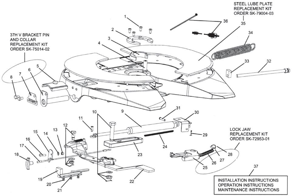
Fig. Description Part No.
01 Cushion ring bolt
02 Cushion ring plate
03 Cushion ring insert
04 Pivot pin for lock jaw
05 Collar
06 Bracket pin
SK7312155
SK310593
SK310592
SK7210667
SK7310595
Fig. Description
21 ¼" split lock washer
22 Release arm assembly
23 Locking bar
24 Cable spring
SK7030305
SK7901637
SK320506
SK7100504
SK1489LZ
SK847
SK7310447
SK7310405 07 Tab washer
08 ½ 13 × ¾ hex bolt
SK7020215 09 Air cylinder
SK210669
SK210670
SK7010103
SK7322101
SK7902013 10 Locking bar bolt assembly
11 ³⁄8" dia. × ¾" lg slic pin
12 Pivot bolt assembly
13 ³⁄8 16 locknut
14 ³⁄8" SAE flat washer
SK7010501
SK71513
SK7040102
SK7030201
15 Handle guide SK7901632
16 ³⁄8 16 × 11.4" button screw
17 Pull cable assembly
18 Thandle air release
19 Lock/unlock plate weldment
20 ¼20 × ¾" hex head cap screw
0136
SK7020602
SK7901646
SK7101200
SK7901622
SK7020228
SK7902008
SK7010201
SK7901005
SK7320507
SK310520
SK7900505
SK5000L&R
SK310802
SK7502016
SK3121027
Application: Highway work Tipper work
also available with: 16mm Base Plate
LP37E 16 mm 20mm Base Plate
LP37E 20 mm
*Note thicker base plate determines extra weight **Note other heights available on request
D-Value
190 kN
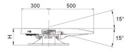
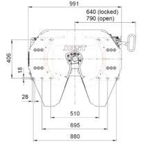
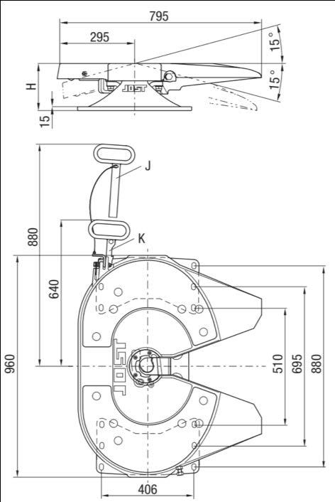
Overall height 234 mm
Imposed load 20000 kgs
Weight approx. 356 kgs (for 16mm base plate)
Approval Number
Twin lockouts.
JSK37E -CTA-036821 LP Subassembly -CTA-047151
Flush bolt heads on mounting plate in chassis mounting zone. Wear ring easily removed from above on JSK37E fifth wheel. Mounting must be carried out in accordance with our instructions.
Half Moon c/w 130mm or 150mm Ped. SK370402
33a Base plate (12mm) incl. 56, 57, 58
SK370612
33b Base plate (16mm) incl. 56, 57, 58 SK370616
33c Base plate (20mm) incl. 56, 57, 58 SK370620
Hex. bolt compl.
SK372104
Countersunk bolt compl. SK372105
Lock out pin compl. with chain (old style) SK370610 36a Lock out pin compl. with R clip (new style) SK370609
SK370604
Tube lock out (old style) SK370605
38a Tube lock out (new style) SK370504
Application: Stock crate Fridge van General freight Tankers
also available with:
16mm Base Plate
20mm Base Plate
LP37CZ 16mm
LP37CZ 20mm
Narrow chassis width available ie European spec
*Note: thicker base plate determines extra weight and height.
**Note: other heights are available on request
D-Value
190 kN
Overall height 234 mm
Imposed load 20000 kgs
Gross comb. weight 135000 kgs
Weight approx. 367 kgs
(for 12mm base plate)
Approval Number
Twin lockouts.
JSK37CZ -CTA-041876
LP Subassembly -CTA-047151
Flush bolt heads on mounting plate in chassis mounting zone. Cast type unit equipped with external king pin grease point for additional lubrication to the jaw. Wear ring easily removed from above on JSK37CZ fifth wheel. Mounting must be carried out in accordance with our instructions.
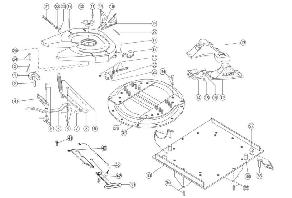
Fig. Description
01 Lock jaw
02 Lock jaw spring
03 Pivot for lock jaw, compl.
04 Locking bar
05 Locking bar bolt, compl.
06 Lever
07 Operating handle
08 Head bolt
09 Double tension spring
10 Wearing ring
11 Socket head bolt
12 Pedestal (185mm)
Pedestal (170mm)
Pedestal (150mm)
13 Upper rubber cushion
14 Lower rubber cushion
15 Mounting bracket
SK1489Z
SK847
SK210667
SK320506
SK322101
SK310518
SK310515
SK1513
SK310520
SK210519
SK212107
SK210401X
SK210421X
SK210402X
SK1259
SK210525
SK1372
16 Socket head bolt, compl. SK212115
17 Split pin
18
SK1974
Fig.
01, 02, 03, 10, 11, 26
01, 02, 03, 26
01, 02, 03, 08, 10, 11, 18, 26
13, 14, 16
Repair kit for locking device
Repair kit for locking device
Repair kit for locking device
Repair kit for rubber bearing
28, 29, 30 Kit for latch
Eye bolt compl. SK212204 25 Grease nipple SK312111
Lubrication tubing with Fig. 27 SK310802
Tubing clamp SK312113 28 Spring Latch 1996 onwards SK312152 29 Bolt for Spring Latch SK3521/03
30 Spring for Latch SK3121/59 31 Ball bearing
KDL9006W
32 Half moon compl. SK370629
33a Base plate (12mm) incl. 36, 37, 38 SK370612
33b Base plate (16mm) incl. 36, 37, 38 SK370616
33c Base plate (20mm) incl. 36, 37, 38 SK370620
34 Hex. bolt compl.
SK372104
35 Countersunk bolt compl. SK372105
36 Lock out pin compl. with chain (old style) SK370610
36a Lock out pin compl. with R clip (new style) SK370609
37 Tube park old style SK370604
38 Tube lock out (old style) SK370605
38a Tube lock out (new style) SK370504
39 Handle Extension
SK3105113
40 Internal Operating Handle SK3105115
41 Head Bolt SK1513
42 Extended Handle Bolt SK242150 43 Cable Extension SK352102
SK322150Z
SK322152Z
SK312150Z
SK212169Z
SK312152 KIT
Application: General freight Tankers Fridge van Stock crate
also available with:
16mm Base Plate
LP37CX 16mm
20mm Base Plate LP37CX 20mm
Narrow chassis width available ie. European spec
*Note thicker base plate determines extra weight and height.
**Note: other heights are available on request
D-value 240kN
Overall height 234mm
Imposed load 24000 kgs
Weight approx. 367 kgs (for 12mm base plate)
Approval Number
Twin lockouts.
JSK37CX -CTA-045374
LP Subassembly -CTA-047151
Flush bolt heads on mounting plate in chassis mounting zone. Cast type unit equipped with external king pin grease point for additional lubrication to the jaw.
Wearing easily removed from above on JSK37CX fifth wheel.
Mounting must be carried out in accordance with our instructions.
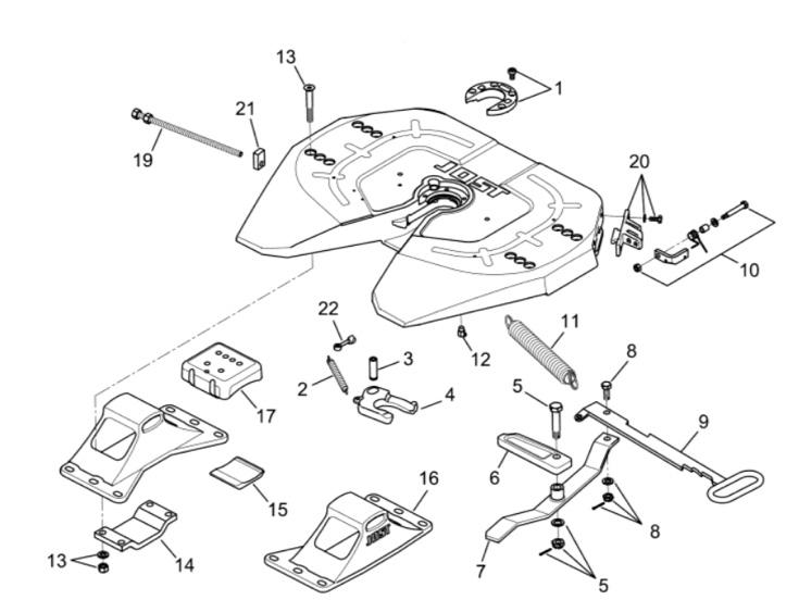
Fig. Description Code
01 Wearing ring and bolts
02 Lock jaw spring
03 Pivot
04 Locking jaw
05 Bolt (complete)
06 Lock bar
07 Lever with bushing
08 Head bolt
09 Lever handle
10 Latch kit
11 Double tension spring
12 Fitting
13 Complete countersunk bolt
14 Mounting bracket
15 Lower rubber cushion
16 Pedestal (150mm)
16a Pedestal (170mm)
16b Pedestal (185mm)
16c Pedestal (220mm)
16d Pedestal (250mm)
16e Pedestal (300mm)
QR00269J00
SK847
SK210667
SK1489Z
SK322101
SK320506
SK310518
SK1513
SK3105/15
SK312152KIT
SK3105/20
SK312111
SK212115
QR00215J01
SK21025
SK210402X
SK210421X
SK210401X
SK210418X
SK210414X
SK210420
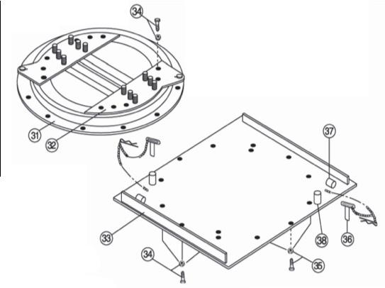
Fig. Description
17 Upper Rubber Cushion SK1259
19 Adjustment screw AD01148B80
20 Guide latch complete security QR00270J00
21 Guide with thread SK320507
22 Pin with eyelet SK212204
31 Ball bearing KDL9006W
32 Half mon complete SK370629
33a Base plate (12mm) inc 36, 37, 38 SK370612
33b Base plate (16mm) inc 36, 37, 38 SK370616
33c Base plate (20mm) inc 36, 37, 38 SK370620
34 Hex bolt complete SK372104
35 Countersunk bolt complete SK372105
36 Lock out pin compl with chain (old style) SK370610
36a Lock out pin compl with R clip (new style) SK370609
37 Tube park (old style) SK370604
38 Tube lock out (old style) SK370605
38a Tube lock out (new style) SK370504
locking claw - items 1, 2, 3, 4, 22 SK322150CX 27 Base plate fastening kit - items 13, 15, 17 (with 4 screws)
SK212169CX
Application: General Freight Tankers
also available with:
16mm Base Plate
DR37CZ 16mm
DR37CZ 20mm
*Note thicker base plate determines extra weight
mm
Gross comb. weight
190 kN
DR Subassembly -CTA-060153
Flush bolt heads on mounting plate in chassis mounting zone. Cast type unit equipped with external king pin grease point for additional lubrication to the jaw. Wearing ring easily removed from above on JSK37CZ
23 Guide piece
for
compl.
(185mm) SK210401X Pedestal (170mm) SK210421X Pedestal (150mm) SK210402X
head bolt, compl. SK212115 17 Split pin SK1974
18 Spring hook SK1436 19 Lubrication fitting SK1989
SK320507
24 Eye bolt compl. SK212204
25 Grease nipple SK312111
26 Tubing compl. SK3353008
27 Tubing clamp SK312113
28 Spring Latch 1996 onwards SK312152
29 Bolt for Spring Latch SK3521/03
30 Spring for Latch SK3121/59 31 Ball bearing KLKDR41AS010K
32 Half moon compl. SK370640
33a Base plate (12mm) incl. 36, 37, 38 SK370630
33b Base plate (16mm) incl. 36, 37, 38 SK370631
33c Base plate (20mm) incl. 36, 37, 38 SK370632
34 Hex. bolt compl. SK372104
35 Countersunk bolt compl. SK372105
36 Lock out pin compl. with chain (old style) SK370509
36a Lock out pin compl. with R clip (new style) SK370514
37 Tube park (old style) SK370604
38 Tube lock out (old style) SK370510
38a Lockout tube (new style) SK370515
39 Handle Extension SK3105113
40 Internal Operating Handle SK3105115
41 Head Bolt SK1513
42 Extended Handle Bolt SK242150
43 Cable Extension SK352102
Fig. Repair Kits Part No.
01, 02, 03, 10, 11
01, 02, 03
01, 02, 03, 08, 10, 11, 18
13, 14, 16
28, 29, 30
Repair kit for locking device
Repair kit for locking device
Repair kit for locking device
Repair kit for rubber bearing
Latch Kit
SK322150Z
SK322152Z
SK312150Z
SK212169Z
SK312152 KIT
Application: Highway work Tipper work
also available with: 16mm Base Plate
DR37E 16mm 20mm Base Plate DR37E 20mm
*Note thicker base plate determines extra weight **Note only available on weld on feet
190 kN
268 mm
20000 kgs
135000 kgs
394 kgs
Complies with ADR 62, 63
JSK37E -CTA-036821 DR Subassembly -CTA-060153
Flush bolt heads on mounting plate in chassis mounting zone. Wearing ring easily removed from above on JSK37E
01 Jaw SK1489Z
02 Jaw Spring SK847
03 Jaw Pivot SK210667
04 Locking Bar
05 Lock Bar Bolt
06 Release Lever
07 Operating Handle
SK320506
SK322101
SK310518
SK310515
08 Head Bolt SK1513
09 Double Tension Spring SK310520
10a Wear Ring Three Bolt
10b Wear Ring Four Bolt
10c Wear Ring Insert
10d Wear Ring Bolt
11 Wear Ring Bolt
12 Swivel Pin
13 Pedestal Bush
SK210519
SK310592
SK310593
SK312155
SK212107
SK310405
SK290520
13a Collar SK310595 14 Swivel Pin Bolt SK312128
Fig.
01, 02, 03
12, 13, 13a, 14, 15
01, 02, 03, 08, 11, 23, 28
10b, 10c, 10d
16, 17, 18
Repair kit for locking device
Repair kit for locking device
Repair kit for locking device
Repair kit for wear ring
Repair kit Latch
Fig. Description Part No. DR 37 E 15 Swivel Pin Plug JS 110112 16 Spring Latch SK312152 17 Bolt for Spring Latch SK352103 18 Spring for Latch SK312159 19 Adjusting Screw SK310597 20 Hex Nut
SK212178 21 Guide Piece
SK320507 22 Eye Bolt Complete
SK212204 23 Grease Line Complete
24 Ball bearing
SK310802
KLKDR41AS010K
25 Half moon cw 130mm Ped. SK370511
26a Base plate (12mm) incl. 56, 57, 58 SK370630
26b Base plate (16mm) incl. 56, 57, 58 SK370631
26c Base plate (20mm) incl. 56, 57, 58 SK370632
27 Hex. bolt compl.
28 Countersunk bolt compl.
SK372104
SK372105 29 Tube lock out (old style)
29a Tube lock out (new style)
30 Tube park
31 Lock out pin compl. with chain
SK370510
SK370515
SK370604
SK370509
31a Lock out pin compl. with R clip (new style) SK370514
SK322152Z
SK3121061
SK3121060Z
SK310594
SK312152 KIT
Application: General freight Tankers Fridge van Stock crate
also available with:
16mm Base Plate
20mm Base Plate
DR37CX 16mm
DR37CX 20mm
*Note thicker base plate determines extra weight
Overall height
268 mm
Imposed load 24000 kgs
Weight approx. 405 kgs (for 12mm base plate)
D-Valve 240kN
Approval Number
Twin lockouts.
JSK37CX -CTA-045374 DR Subassembly -CTA 060153
Flush bolt heads on mounting plate in chassis mounting zone. Cast type unit equipped with external king pin grease point for additional lubrication to the jaw.
Wearing ring easily removed from above on JSK37CX fifth wheel.
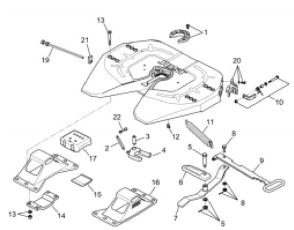

Fig. Description Code
01 Wearing ring and bolts
QR00269J00
02 Lock jaw spring SK847 03 Pivot SK210667 04 Locking SK1489Z
05 Bolt (complete) SK322101
06 Locking bolt SK320506
07 Lever with bushing SK310518
08 Head bolt SK1513
09 Lever handle SK3105/15
10 Latch kit SK312152KIT
11 Double tension spring SK3105/20 12 Fitting SK312111
13 Complete countersunk bolt SK212115 14 Mounting bracket QR00215J01
15 Lower rubber cushion SK21025
16 Pedestal (150mm) SK210402X
16a Pedestal (170mm) SK210421X
16b Pedestal (185mm) SK210401X
16c Pedestal (220mm) SK210418X
16d Pedestal (250mm) SK210414X
16e Pedestal (300mm) SK210420
17 Upper Rubber Cushion SK1259 19 Adjustment screw AD01148B80
20 Guide latch complete security QR00270J00
21 Guide with thread SK320507
22 Pin with eyelet SK212204
31 Ball bearing KLKDR41AS010K
32 Half mon complete SK370640
33a Base plate (12mm) inc 36, 37, 38 SK370630
33b Base plate (16mm) inc 36, 37, 38 SK370631
33c Base plate (20mm) inc 36, 37, 38 SK370632
34 Hex bolt complete SK372104
35 Countersunk bolt complete SK372105
36 Lock out pin compl with chain (old style) SK370509
36a Lock out pin compl with R clip (new style) SK370514
37 Tube park (old style) SK370604
38 Tube lock out (old style) SK370510
38a Tube lock out (new style) SK370515
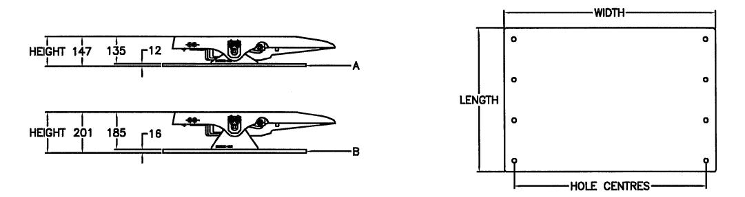
Note: Height is measured with fifthwheel and pedestals assembled together, refer example above. (Example, 16mm plate with 185 mm Pedestals= 201 mm overall)
255mm Pedestals, with 16mm Plate
If using a 37-027 narrow spec fifthwheel, 15 mm is to be added to the overall height. Other base plate options available. Custom styles and drilling available. For further information please contact your local JOST branch
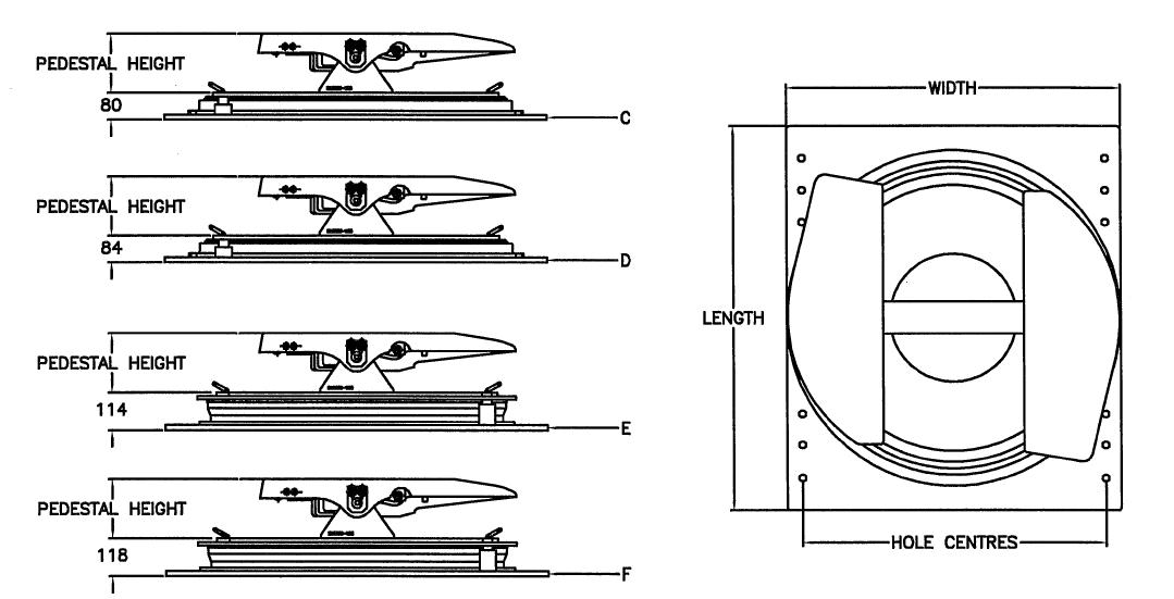
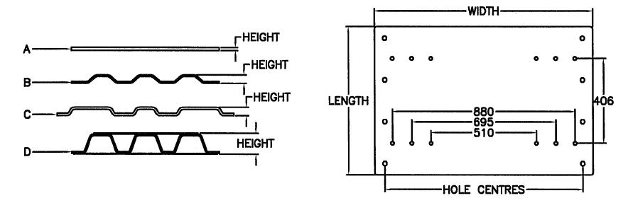
*D-value and imposed load rating reduced if combination height exceeds 300 mm
Other base plate options available. Custom styles and drilling available. For further information please contact
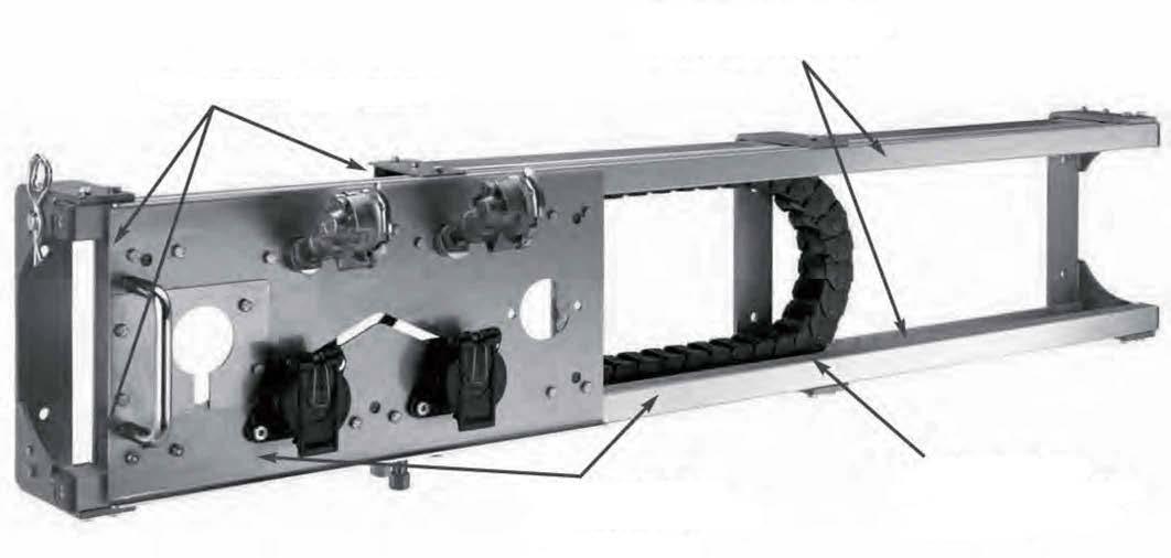
Maintenance-free sliding blocks
Stainless steel and other corrosion-resistant materials.
Guide rails ensure precise, smooth lateral movement
Maintenance-free protection of pneumatic and power cables
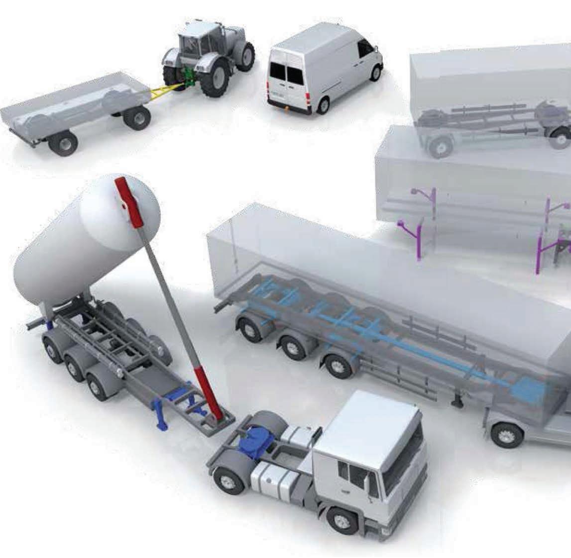
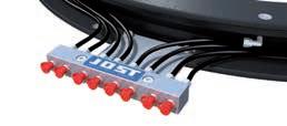
Coupling and uncoupling without the need to raise or lower the unit
• Fast and easy attachment and disconnection of pneumatic and power cables.
• Access from side of vehicle to alleviate OH & S issues
• Easy Connect is universal and directly fits most trailer models
• Prevents damage to spiral connections (suzies, see illustration below)
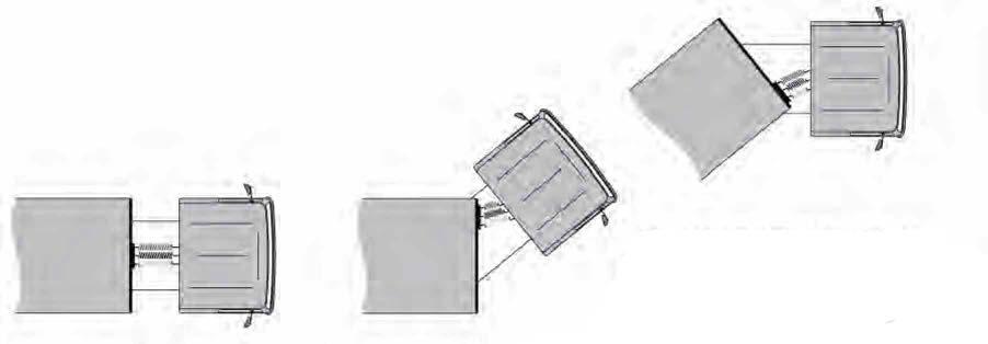
Easy connect system provides for lateral movement when negotiating bends. This prevents stress and excessive strain on the spiral connections (suzies).
Part No: SKE0105000000
3½" and 2"
locked with spring hook inserted set for coupling
hole to use when locking open the operating handling when exchanging lock jaw
JSK38G cardan mounting
• wear resistant bushes
• lateral movement up to a max. of 7° for off road operation.
• lateral movement can be limited to approx. 0° for highway operation.
JSK38C, JSK39C, JSK38DV Rubber mounting
• shock absorbing by large rubber pads slack and maintenance free
• Oil and grease resistant
Operating instructions
The outfit should be parked on a flat and even road surface.
Coupling-up:
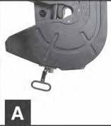
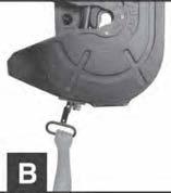
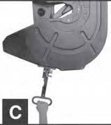
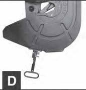
1. The fifth wheel must be in the reset position, i.e. the end of the operating handle standing out approx. 300 mm otherwise: Raise secondary safety latch’ (A) and move handle forward to unlock (B). Pull handle to end position (C).
2. Skid plate of semi trailer should be approx. 50 mm lower than the top of the fifth wheel.
IMPORTANT: Loss of pressure in the air suspension of the trailer can alter the height of the king pin.
3 Reverse tractor - the mechanism locks automatically.
4 Check that the skid plate is resting on the fifth wheel plate with no gap between the two.
5 Ensure secondary safety latch is engaged.
IMPORTANT: The secondary safety latch in the secured position ensures the locking mechanism is closed. If secondary safety latch is in raised position, the coupling-up procedure must be repeated.
Un-coupling:
1. Raise secondary safety latch (A). Move handle forward to unlock (B). Pull handle to end position (C)
2 Drive tractor away. The fifth wheel mechanism will automatically assume the coupling-up position (D)
Lateral movement on type JSK38G
The lateral movement should only be engaged for off-road use. On the road, and especially at higher speeds, it must be blocked for safety reasons.
To set the lateral movement: For normal road Use:
1. Release the hex bolts (2 each side - width over flats 19 mm).
2. Push both blocks into the end of the oblong hole.
3 Re-tighten hex bolts (torque 80 Nm).
For off-road use:
1. Release the hex bolts (2 each side - width over flats 19 mm).
2. Pull both blocks out to the end of the oblong hole.
3 Re-tighten the hex bolts (torque 80 Nm).
Maintenance instructions:
1. Uncouple semi-trailer at least once a week, certainly after more than 5000 km. Clean semi-trailer skid plate and fifth wheel plate. Lubricate fifth wheel plate, locking mechanism, fifth wheel throat and king pin, with heavy duty grease. We recommend the use of high pressure grease (EP) with MoS2 or graphite additive, for example BP L21, M, BP HTEP 1, BP LS 2, Esso universal grease M, Shell Retinax AM. Check operating handle and release lever pivots for free movement - clean and lubricate.
2 The bearings of the lock lever (item 28) and of the pedestals of the JSK38 G-1 and the pivot bearing of the JSK50 are to be regreased through grease nipples provided at each maintenance interval. The rubber cushions of the JSK38 C-1 are maintenance free. According to operating conditions we recommend checking parts for wear at 50,000 and 100,000 km distance driven.
A heavy duty fifth wheel coupling for operation under arduous conditions.
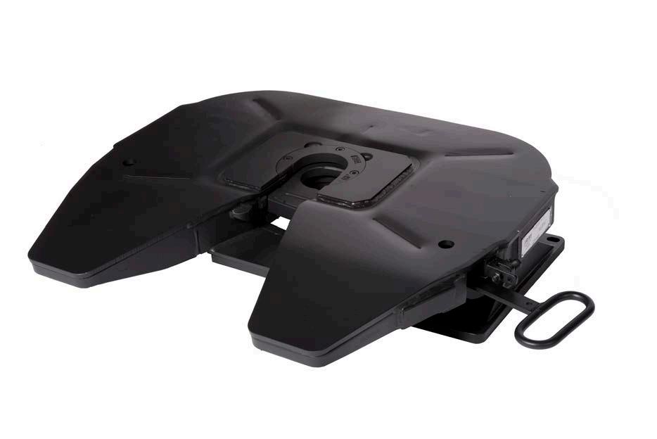
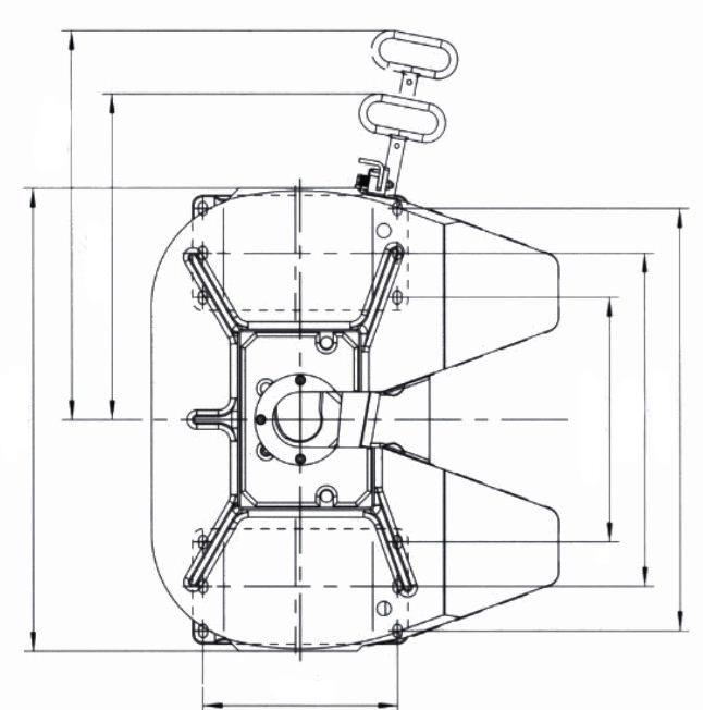
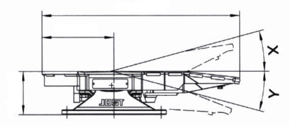
Increased load (up to 28,000kg). With rubber bearing (model “C”): rubber cushions are shock- absorbent and maintenance-free.
Technical specification:
Rubber bearing
The fifth wheel coupling complies with the directives/standards as per 94/20/EC - Class S, DIN 74084 and ISO 3842. Suitable for 3,5" (90) king pins as per 94/20/EC, DIN 74083 and ISO 4086. Fitted on a mounting plate.
Imposed weight 28,000 kg D-value
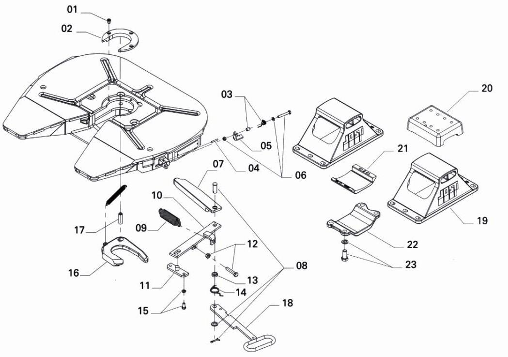
Fig. Description
01 Socket head bolt
Part No.
SK242108
02 Wearig ring, complete SK242156
03 Spring noose, complete SK312159
04 Jaw tension spring SK210638
05 Latch kit, complete SK312152 KIT
06 Hexagon bolt, complete SK352103
07 Locking bar
SKE003750000
08 Bar bolt, complete SKE003760001
09 Double tension spring SK240523
10 Lever SK240504
11 Bearing SK240515
12 Hexagon bolt, complete SK242152
13 Washer SK240519
14 Spring noose
SK240509
15 Hexagon bolt, complete SK244153
16 Lock jaw
SK240514Z
17 Pivot SK240518
18 Handle SKE003740000
Fig. Repair Kits
01, 02, 04, 09, 16, 17
20, 21, 23
05, 03, 06
Repair kit for lock 3.5"
Repair kit for bearing
Repair kit for latch, complete
Fig. Description Part No.
19a Pedestal 160mm
SK240405
19b Pedestal 190mm SK240401
19c Pedestal 250mm SK240404
20 Rubber cushion, upper SK2006
21 Rubber cushion, lower SK2007
22 Bridge SK2005
23 Hexagon bolt, complete SK242155
Part No.
SK242176
SK242178
SK312152 KIT
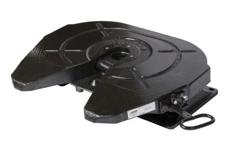
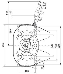
A heavy duty fifth wheel coupling for operation under arduous conditions.
The well known JOST locking device together with the maintenance free rubber cushions ensures a high degree of stability and safety on the road.
This fifth wheel is available for use with 3½" and 2" king pins.
The conversion of a 3½" or 2" locking mechanism or vice versa can easily be carried out with standard tools, without removing the fifth wheel coupling from the truck.
160 mm optional (Bolt on/weldable feet)
190 mm optional (Bolt on/weldable feet)
250 mm optional (Bolt on only)
Mounting must be carried out in accordance with our instructions.
The right to alter specifications is reserved.
Fig. Description
01 Socket head bolt
02 Wearing ring 3½", compl. with 01
02 Wearing ring 2", compl. with 01
03 Nut and bolt
04 Lubrication tube
07 Tension spring
08 Hexagon bolt, compl.
09 Latch
11 Hexagon bolt, compl.
13 Spring noose with spacer
15 Latch holder, compl. with 14
16 Latch, compl. incl. 13,14,17
Part No.
SK242108
SK242156
SK242157
SK1989
SK220512
SK210638
SK242151
SK240527
SK242150
SK312159
SK2405084
SK312152 KIT
17 Hexagon bolt, compl. SK352103
18 Locking bar
SK240501
19 Bar bolt, compl. SK212225
20 Double tension spring
21 Lever
Fig. Description
23 Hexagon bolt, compl.
24 Washer
25 Spring noose
26 Hexagon bolt, compl.
27 Lock jaw 3½"
27 Lock jaw 2’’
27a Lock jaw, 3½" (Greaseable)
27a Lock jaw, 2" (Greaseable)
28 Pivot
29 Handle (standard version)
Part No.
SK242152
SK240519
SK240509
SK242153
SK240514
SK240513
SK240514Z
SK240513Z
SK240518
SK2405066
34 Handle, extended SK2405066 EXT
35a Pedestal 160mm SK240405
35b Pedestal 190mm
SK240523
SK240504SA
22 Bearing SK240515
SK240401
35c Pedestal 250mm SK240404
36 Rubber cushion, upper SK2006
37 Rubber cushion, lower SK2007
38 Bridge SK2005
39 Hexagon bolt, compl. SK242155
Fig. Repair Kits
01, 02, 07, 20, 27,28
Repair kit for lock 3½"
SK242176 01, 02, 07, 20, 27,28
Repair kit for lock 2" SK242177 36, 37, 39
01, 02, 07, 27
01, 02, 07, 27
Repair kit for bearing SK242178 Conversion
kit from 3½" to 2" lock
kit 2" to 3½"
Low profile stabilised fifth wheel assembly
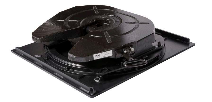
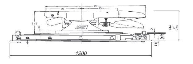
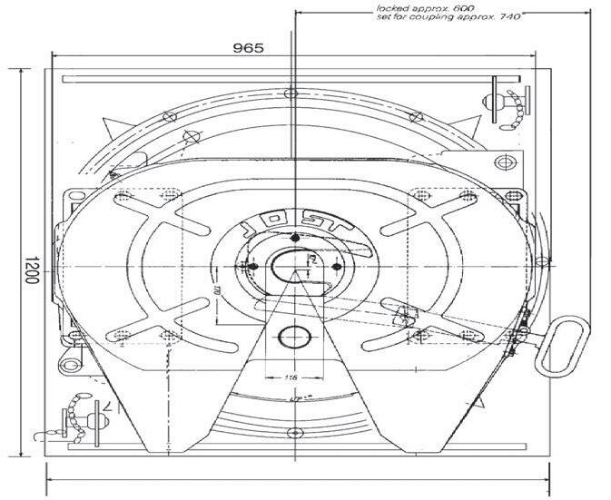

Heavy duty
Applications: Stock crate Fridge van General freight Tankers
Standard with 16 mm base plate optional: 20 mm base plate LP38C 20mm
*Note thicker base plate determines extra weight and height.
D-Value
JSK38C1W 240 kN
JSK38C2W 170 kN Overall height (with 190 mm Feet) 274 mm (with 160 mm Feet) 244 mm
Imposed load 20000 kgs
Weight approx. 444 kgs (for 16 mm base plate)
Approval Number
JSK38C1 ECE E1 55R-01 0471
JSK38C2 ECE E1 55R-01 0472 LP Subassembly CTA-047151
Twin lockouts.
Flush bolt heads on mounting plate in chassis mounting zone. Cast type unit equipped with JSK38 fifth wheel extra heavy duty unit. Jaws sizes can be changed from 50 mm or 90 mm diameter. Mounting must be carried out in accordance with our instructions.
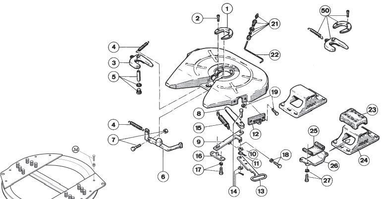
01 Wearing ring 3½" compl. with item 2
01 Wearing ring 2" compl. with item 2
02 Socket head bolt
03 Lock jaw 3½"
03 Lock jaw 2"
04 Lock jaw spring
05 Bolt complete
SK242156
SK242157
SK242108
SK240514
SK240513
SK210601
SK240527
Fig. Description Part No.
21 Grease nipple complete
22 Grease tube
23 Upper rubber cushion
24a Pedestal 160 mm Bolt on/weldable
24b Pedestal 190 mm Bolt on/weldable
24c Pedestal 250 mm Bolt on/weldable
25 Lower rubber cushion
26 Mounting bracket
26a For use with 160mm pedestals
SK1976
SK220512
SK2006
SK240405
SK240401
SK240404
SK2007
SK2005
SK20051 27 Hexagon head bolt
SK242155 29 Ball bearing
KDL 9006W 30 Half moon compl.
31 Base plate (16mm) incl. 34, 36
31b Base plate (20mm) incl. 34, 36
32 Hex. bolt compl.
33 Countersunk bolt compl.
34 lock out pin compl. old style
34a Lock out pin, new style
head bolt complete SK242152
19 Hexagon head bolt complete
SK242150
20 Spring hook complete SK1436
03, 04, 05, 15, 20
03, 04, 05, 15, 20
SK370629
SK370616
SK370620
SK372104
SK372105
SK370610
SK370609 35 Tube park old style
SK370604 36 Tube lock out
SK370504
SK370605 36b Tube lock out, new style
with mounting pattern according to DIN standard 74081 and 74084
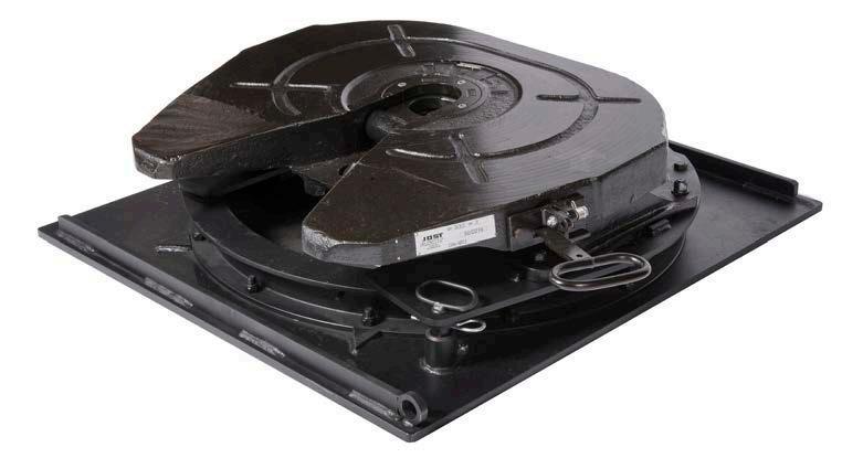
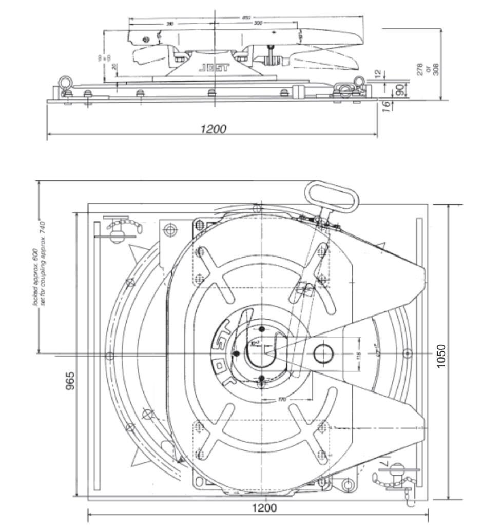
Heavy duty
Applications: Stock crate Fridge van General freight Tankers
Standard with 16 mm base plate optional: 20 mm base plate DR38C 20mm
*Note thicker base plate determines extra weight and height.
D-Value
JSK38C1W
260 kN
JSK38C2W 170 kN
Overall height (with 190 mm Feet)
308 mm (with 160 mm Feet) 278 mm
Imposed load
20000 kgs
Weight approx. 472 kgs (for 16mm base plate)
Approval Number
JSK38C1 ECE E1 55R-01 0471
JSK38C2 ECE E1 55R-01 0472 DR Subassembly CTA-060153
Twin lockouts.
Flush bolt heads on mounting plate in chassis mounting zone. Cast type unit equipped with JSK38 fifth wheel extra heavy duty unit . Jaws sizes can be changed from 50 mm or 90 mm diameter. Mounting must be carried out in accordance with our instructions.
Mounting must be carried out in accordance with our instructions.
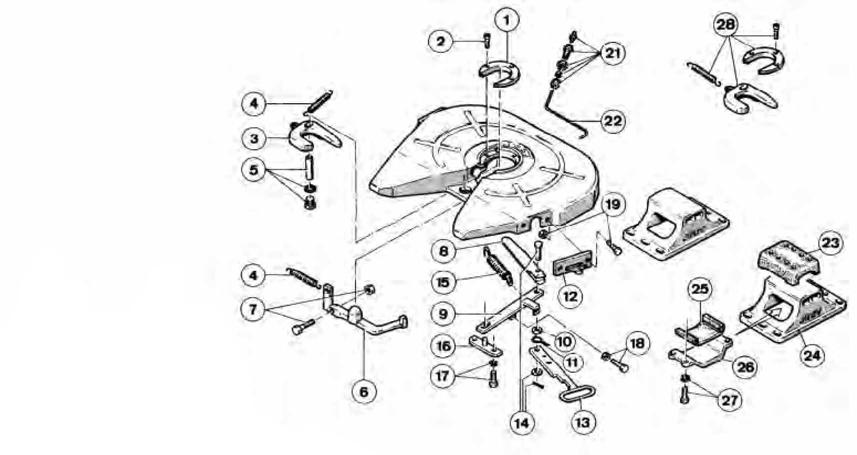
Fig. Description Part No.
01 Wearing ring 3½" compl. with item 2
SK242156
01 Wearing ring 2" compl. with item 2 SK242157
02 Socket head bolt
03 Lock jaw 3½"
03 Lock jaw 2"
04 Lock jaw spring
05 Bolt complete
06 Stopper
07 Hexagon head bolt
08 Locking bar
Fig. Description
SK242108
SK240514
SK240513
SK210601
SK242154
SK240527
SK242151
SK240501
09 Lever SK240504
10 Disc
SK240519
11 Spring loop SK240509
12 Support bracket
SK2405084
13 Operating handle SK240502
14 Locking bar bolt
SK212114
15 Double tension spring SK240523
16 Support SK240515
17 Hexagon head bolt complete SK242153
18 Hexagon head bolt complete SK242152
19 Hexagon head bolt complete SK242150
01, 03, 04, 05, 15
01, 03, 04, 05, 15
23, 25, 27
Part No.
21 Grease nipple complete SK1976
22 Grease tube SK220512
23 Upper rubber cushion SK2006
24a Pedestal 160 mm Bolt on/weldable SK240405
24b Pedestal 190 mm Bolt on/weldable SK240401
24c Pedestal 250 mm Bolt on/weldable SK240404
25 Lower rubber cushion SK2007 26 Mounting bracket SK2005
26a For use with 160mm pedestals SK20051 27 Hexagon head bolt SK242155 29 Ball bearing KLKDR4100010K
30 Half moon compl. SK370440
31 Base plate (16mm) incl.56,57,58 SK370631
31b Base plate (20mm) incl.56,57,58 SK370632
32 Hex. bolt compl. SK372104
33 Countersunk bolts compl SK372105 34 Lock out pin, old style SK370509 34a Lock out pin, new style SK370514 35 Tube park SK370604
Tube lock out, old style SK370510
Tube lock out, new style SK370515
with mounting pattern according to DIN 74 081 and 74 084
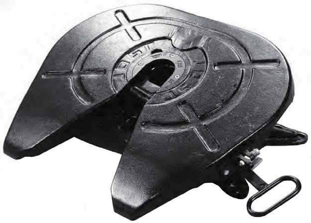
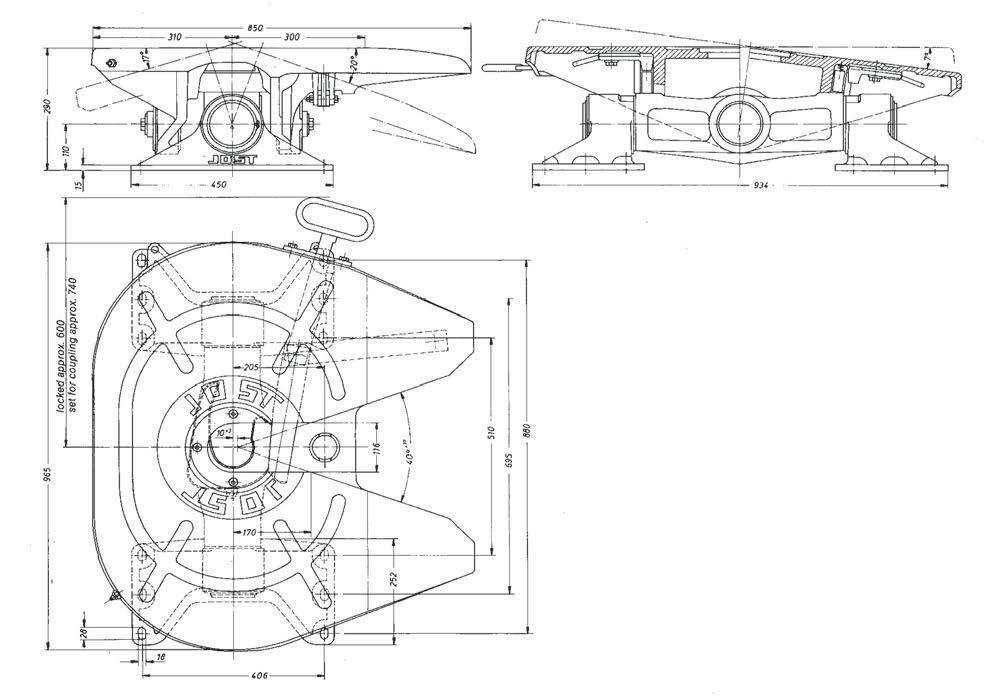
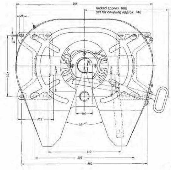
A heavy duty fifth wheel coupling for operation under arduous maintenance free cardan mounting ensures a high degree of The lateral movement of 7° can be reduced to 0° for normal
The conversion of 2" & 3½" locking mechanism or vice versa can easily be carried out with standard tools, without removing the fifth wheel coupling from the tractive unit. Suitable for all
0443
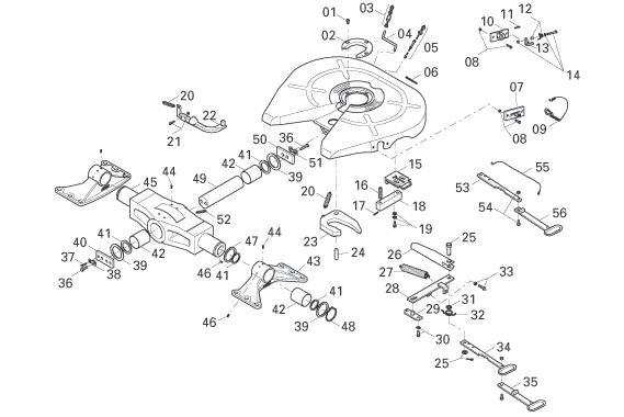
01 Socket head cap screw
02 Wearing ring 3½" compl. with item 1
02 Wearing ring 2" compl. with item 1
03 Grease nipple compl.
04 Grease tube
05 Schmierleitung, compl. with item 6
06 Tubing clamp
07 Guide plate up to series 70
08 Hexagon head bolt comp.
09 Spring hook/chain up to series 70
10 Latch plate compl. with 11 from series 72
11 Split pin
12 Spring compl. with spacer from series 72
13 Latch compl. from series 72
14 Bolt compl. form series 72
15 Cover plate
16 Thrust spring
SK242108
SK242156
SK242157
SK1976
SK1989
SK240802
SK312113
SK240522
SK242150
SK1436V
SK2405084
000.003.027
SK292130
SK312152
SK352103
SK250622
30 Hexagon head bolt compl.
31 Disc
32 Spring loop
33 Hexagon head bolt compl.
34 Operating handle
35 Handle
36 Hexagon bolt
37 Hexagon bolt
38 Security plate
39 Distance ring
40 Plate
41 Seal
42 Bush
43 Pedestal with 42, 44, 46
44 Dowel pin
45 Lock lever compl.
SK252110
SK250615 17 Clamping sleeve
18 Block SK250635
19 Hexagon bolt
20 Lock jaw spring
21 Hexagon head bolt compl.
22 Pin
23 Lock jaw 3½"
23 Lock jaw 2"
24 Pivot bolt
25 Pivot bolt compl.
26 Locking bar
27 Double tension spring
28 Lever
Fig.
SK252150
SK210601
SK242151
SK240527
SK240514
SK240513
SK240518
SK212114
SK240501
SK240523
46 Grease nipple
47 Distance plate
48 Circlip
49 Pivot
50 Lock
51 Security plate
52 Grease nipple
53 Extended handle lower part
54 Hexagon bolt
55 Latch cord compl.
56 Extended handle grip
SK240515
SK242153
SK240519
SK240509
SK242152
SK240566
SK2405066
SK2034
SK252118
SK250421
SK250414
SK250418
SK252107
SK250416
SK252152
SK1533
SK252151
SK252104
SK11921
SK1435
SK240504 Fig. Description Part No. 29 Support
SK250417
SK250419
SK250420
SK252157
SK2405067
SK242150
SK352102
SK3105113
01, 02, 05, 09, 20, 23, 24, 27 Repair kit for locking device 3½"
01, 02, 05, 09, 20, 23, 24, 27 Repair kit for locking device 2"
35, 54, 55 Handle extension SK3121063
Conversion kits
01, 02, 20,23 Conversion from 3½" pin to 2" pin
01, 02, 20,23 Conversion from 2" pin to 3½" pin
Suitable for 3½" king pins. Greaseless option available
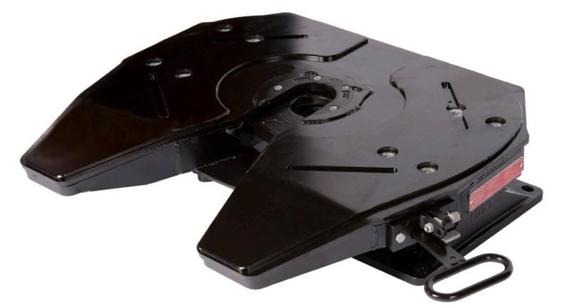
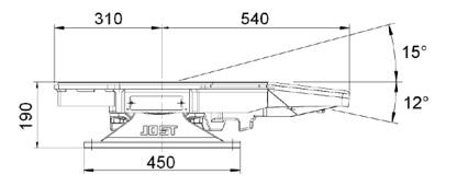
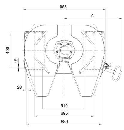
Heavy duty Applications: Mining Stock crate Fridge van Forestry Off road
Suitable for 3½" king pins
D-Value 275 kN
Overall height
190 mm
160 mm
250 mm
Imposed load 26000 kgs
Weight approx. 232 kgs
Approval Number CTA-045375
In accordance with the standards: ISO3842, DIN 74081
Features
A heavy duty fifth wheel coupling for operation under arduous conditions.
Removable wear plates, bolted to the top plate, allowing an easier and cheaper maintenance. Also available in greaseless. Manual adjustment for the locking mechanism to extend the life cycle.
Rubber cushions pad mount. High reliability in the locking mechanism.
Mounting must be carried out in accordance with our instructions.
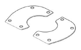
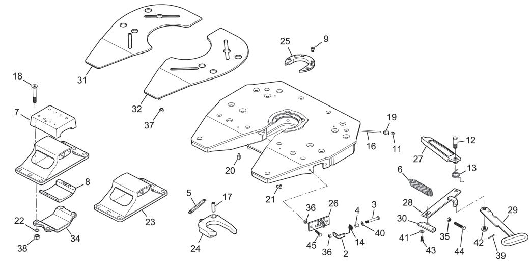
09, 05, 06, 17, 24, 25
07, 08, 18, 22, 38
kit for bearing SK242180 02, 03, 04 Repair kit for spring latch SK312152 KIT
25, 09 Wear Ring, compl. with 09 QR00244J00
Suitable for 3½" king pins. Greaseless option available
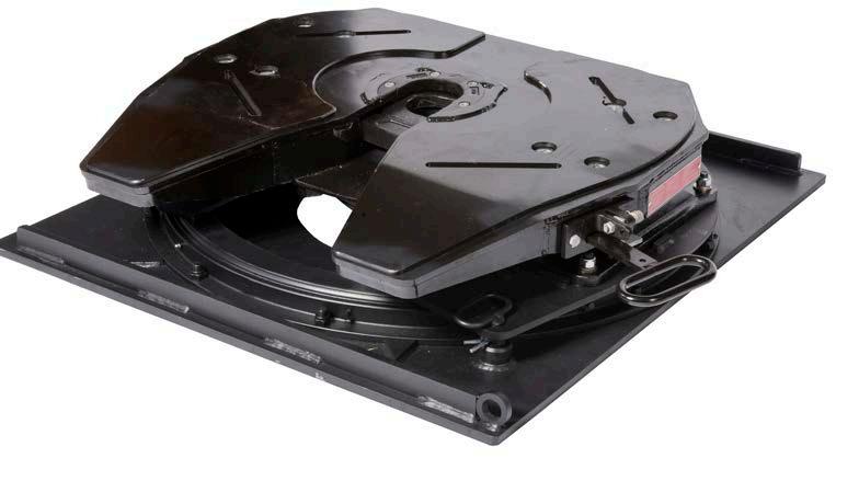
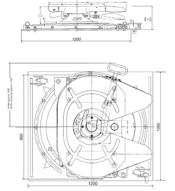
Heavy duty
Applications: Stock crate Fridge van General freight Tankers
Standard with 16 mm base plate optional: 20 mm base plate LP39C 20mm
*Note thicker base plate determines extra weight and height.
D-Value
JSK39CS, CSW 240 kN
Imposed load 24000 kgs
Weight approx. 425 kgs (for 16mm base plate)
Approval Number
Twin lockouts.
JSK39CS / CSW CTA-045375
LP Subassembly CTA-047151
Flush bolt heads on mounting plate in chassis mounting zone. Cast type unit equipped with JSK39 CS fifth wheel extra heavy duty unit. Mounting must be carried out in accordance with our instructions.
Items
05, 06, 09, 17, 24, 25
07, 08, 18, 22, 38
02, 03, 04
Repair kit for lock 3.5"
Repair kit for bearing
Repair kit for spring latch
QR00197J01 34 Bridge
SK2005 37 Hex Nut M12
ST03006B80 38 Hex Nut M20
42 Castellated nut M20
ST03007B81
ST12002J80 43 Hex Bolt, complete M12 × 25 SK242153
44 Hex Bolt, complete M14 × 70 SK242152
45 Hex Bolt, complete M10 × 40
46 Replacement insert kit
46a Replacement greaseless insert kit
51 Ball bearing
52 Half moon compl.
53 Base plate (16mm) incl. 34, 36
53a Base plate (20mm) incl. 34, 36
54 Hex. bolt compl.
55 Countersunk bolt compl.
56 Lock out pin, old style
56a Lock out pin, new style
57 Tube park
58 Tube lock out, old style
58a Tube lock out, new style
SK242150
QR00248J00
SK3106039CS
KDL9006W
SK370629
SK370616
SK370620
SK372104
SK372105
SK370610
SK370609
SK370604
SK370605
SK370504
QR00245J00
SK242180
SK312152 KIT 09, 25
QR00244J00 Repair Kits
Wearing Ring, compl. with 09
Suitable for 3½" king pins. Greaseless option available
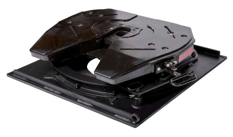
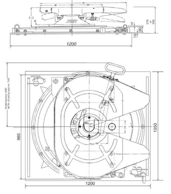
Heavy duty
Applications: Stock crate Fridge van General freight Tankers
Standard with 16 mm base plate optional: 20 mm base plate DR39C 20mm
*Note thicker base plate determines extra weight and height.
D-Value
JSK39 CS & CSW
275 kN
Imposed load 26000 kgs
Weight approx. 485 kgs (for 16mm base plate)
Approval Number JSK39CS / CSW CTA-045375 DR Subassembly CTA-060153
Twin lockouts.
Flush bolt heads on mounting plate in chassis mounting zone. Cast type unit equipped with JSK39 CS fifth wheel extra heavy duty unit. Mounting must be carried out in accordance with our instructions.
Mounting must be carried out in accordance with our instructions.
23c Pedestal 250mm SK240404
24 Jaw 3½"
SK240514Z
24a Jaw 3½" (greaseable) SK240514 25
05, 06, 09, 17, 24, 25
07, 08, 18, 22, 38
02, 03, 04
09, 25
Repair kit for lock 3.5"
Repair kit for bearing
Repair kit for spring latch
Wearing Ring, compl. with 09
Wear plate
QR00195J01
QR00197J01
Bridge SK2005
Hex Nut M12 ST03006B80 38 Hex Nut M20 ST03007B81
42 Castellated nut M20 ST12002J80
43 Hex Bolt, complete M12 × 25 SK242153
44 Hex Bolt, complete M14 × 70 SK242152
45 Hex Bolt, complete M10 × 40 SK242150
46 Replacement insert kit
46a Replacement greaseless insert kit
QR00248J00
SK3106039CS 51 Ball bearing
52 Half moon compl.
53 Base plate (16mm) incl. 34, 36
KLKDR4100010K
SK370640
SK370631
53a Base plate (20mm) incl. 34, 36 SK370632
54 Hex. bolt compl. SK372104
55 Countersunk bolt compl. SK372105
56 Lock out pin, old style
SK370509
56a Lock out pin, new style SK370414
57 Tube park
58 Tube lock out, old style
SK370604
SK370510
58a Tube lock out, new style SK370515
QR00245J00
SK242180
SK312152 KIT
QR00244J00
A heavy duty fifth wheel for arduous conditions D rating 300 kN imposed load up, to 50,000 kg.
Suitable for all types of rear axle steering systems.
Weight: 290 Kg.
Bolt on type Pedestals
Approval Number - ECE E1 55R-01 2504
Mounting must be carried out in accordance with our instructions.
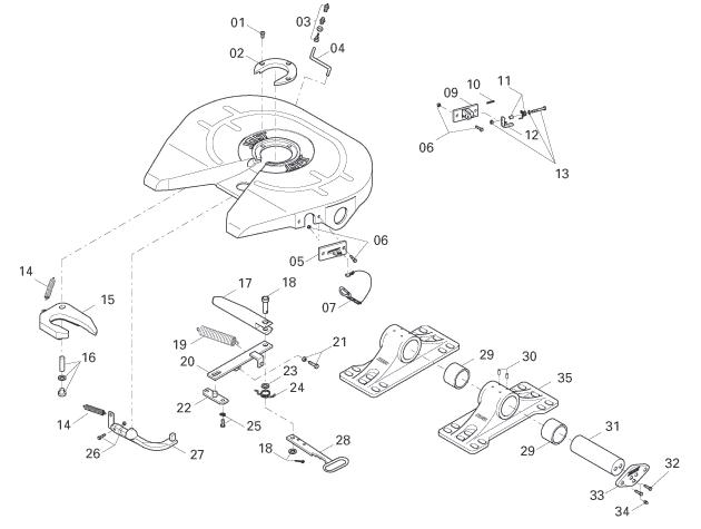
Description
01 Socket head bolt
SK242108
02 Wearing ring 3½", compl. with 1 SK242156
03 Nut and bolt SK1976 04 Lubrication tube
SK1989003
05 Guide plate SK240522
06 Hexagon bolt, complete SK242150 07 Spring hook, complete SK1436
09 Latch holder, compl. with 10 SK2405084
Clamping pin 000.003.027
Spring noose with spacer SK292130 12 Latch, complete SK312152
13 Hexagon bolt, complete SK352103
14 Tension spring SK210638
15 Lock jaw 3½"
SK240514
15a Lock jaw 3½" to suit grease nipple SK240514Z
16 Bolt, complete SK242154
17 Locking bolt
SK240501
18 Bar bolt, complete SK212114
Fig. Description Part No.
19 Double tension spring
SK240523
20 Lever SK240504
21 Hexagon bolt, complete SK242152
22 Bearing SK240515
23 Washer SK240519
24 Spring noose SK240509
25 Hexagon bolt, complete SK242153
26 Hexagon bolt, complete SK242151 27 Latch SK240527
28 Handle SK2405066
29 Bearing bushing SK280503
30 Cylindrical notched pin SK1533 31 Pivot pin SK280501 32 Locking bolt SK252105
Plate SK280502 34 Grease nipple SK252104 35 Pedestal, compl. with 29 + 30 SK282151
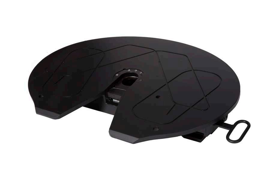
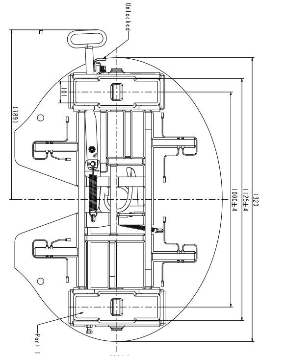
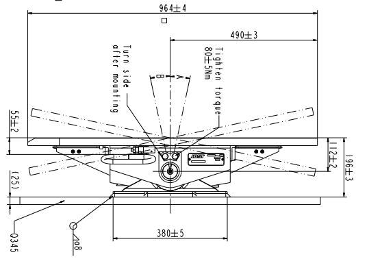
A heavy duty fifth wheel coupling for operation under arduous conditions.
Increased load (up to 75,000kg).
With pivot bearing weld on pedestals.
Technical specification:
Pin and bush
The fifth wheel coupling complies with the directives/ standards as per 94/20/EC – Class S, DIN 74084 and ISO 3842. Suitable for 3.5" (90) king pins as per 94/20/EC, DIN 74083 and ISO 4086. Fitted on a mounting plate.
Imposed weight 75,000 kg
D–value 400 kN
Weight 450 kg
Approval Number CTA-046422
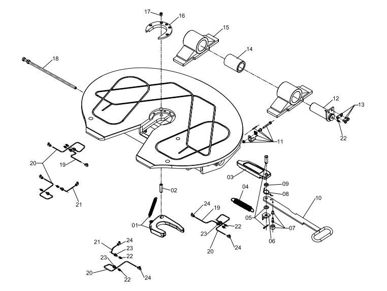
SK242108
SK8301301
SK8301220
SK8301221
SK8301222
SK8301308
SK8301310
SK8301309
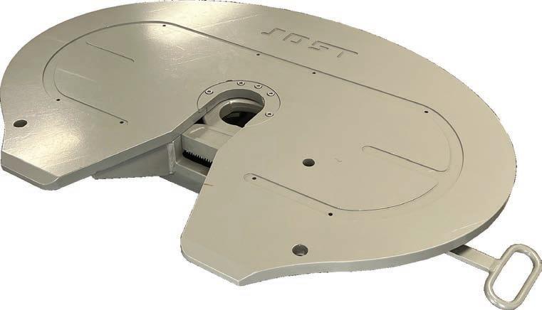
Extreme heavy duty fifth wheel coupling for use in offroad applications.
4’’ fifth wheel.
Compatible with 4’’ / 100mm king pins.
Imposed load 80t.
GCM rating 385T *combination specific.
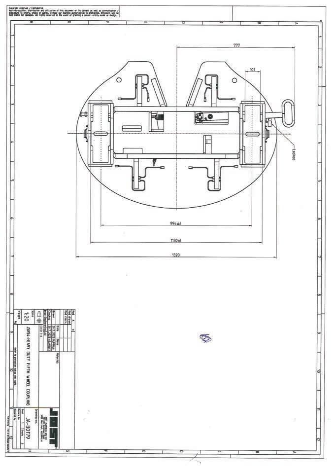
Technical specification:
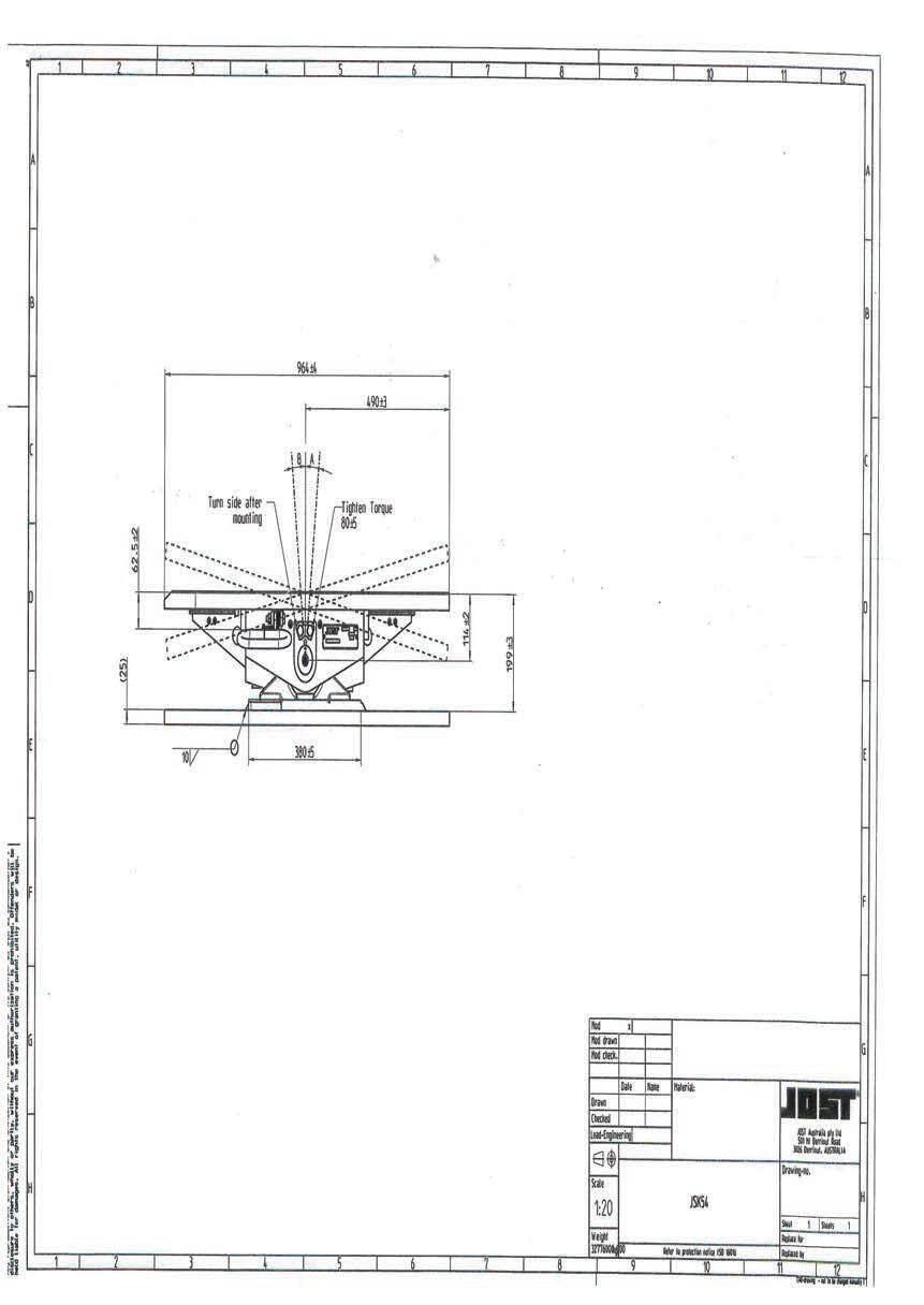
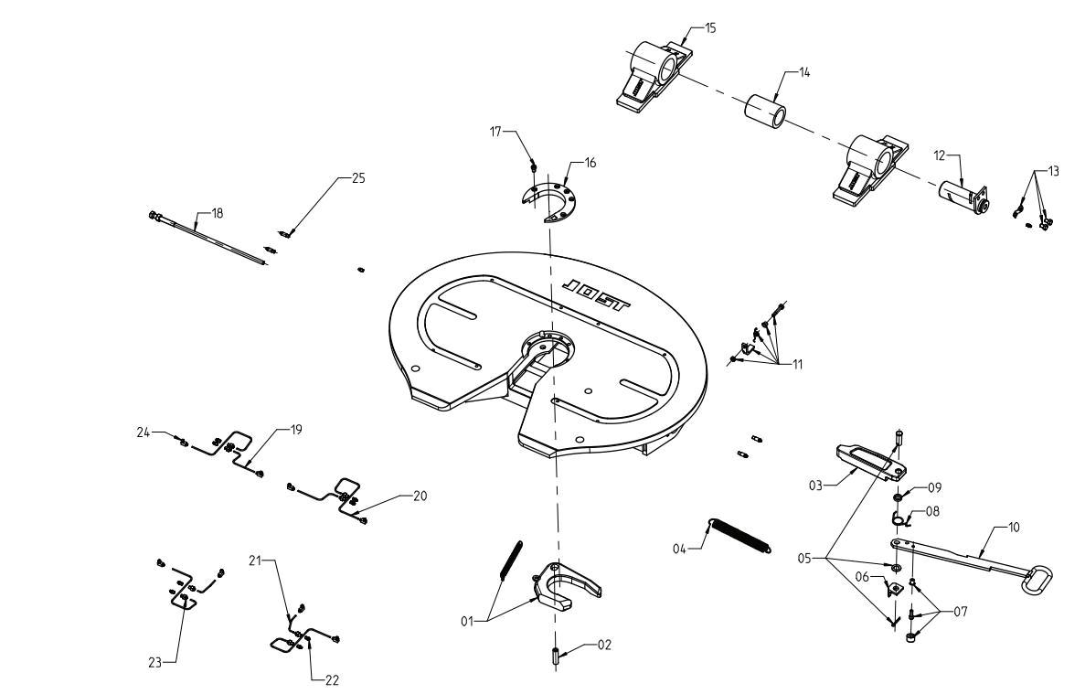
SK8303-005
SK8303-307
SK8303-209
SK8301-210-01
SK8301-006
SK8101-206
SK8301-007
SK2405-009
SK8101-305
SK8303-213
SK8301-008
SK8301-205
SK2921-038
SK8301-224
SK8303-223
SK2421-008-02
SK8301-301
SK8301-220
SK8301-221
SK8301-222
SK8301-308
SK8301-310
SK8301-309
SK8301-308-01
For fifth wheel couplings with mounting pattern according to DIN 74084, for example JSK38C1 and JSK38G1
MP0118
Weight approx. 94kg
Drilling pattern according to DIN standard 74084 and ISO 3842
(use for JSK38 with 160mm pedestals)
Weight approx. 90kg
Drilling pattern according to DIN standard 74084 and ISO 3842
The mounting plates are suitable for all types of semi-trailers with rear axle steering systems.
Suitable for fifth wheel couplings up to 290 mm mounting height.
Imposed load
Weight approx. 120kg
Drilling pattern according to DIN standard 74084 and ISO 3842
36000 kgs
D-Value 260 kN
For fifth wheel couplings with JOST mounting pattern according to JOST standard type JSK38C and JSK38G.
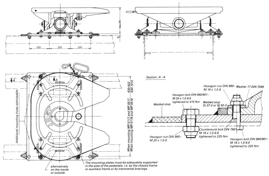
welding process: E II
filler material: E 4320 B9 DIN 1913 alternative welding process: MAG C alternative welding process: Griduct S-V5 green, resp. Griduct S-V4 red or K 5, resp. K 52, resp. K 56 (Westf. Union) or E MK 7, resp. E Mk 6 (Bohler)
(Messer)
When mounting the fifth wheel according to DIN 74084 JOST mounting plate use 12 bolts M 16, preferably M 20 × 1,5 for JSK38C1 and JSK38G1.
To fix the mounting plate on to the vehicle chassis at least 6 bolts M 16 × 1,5, preferably M 16 × 1,5, grade at least 8.8 respectively 4 × 20, preferably M 20 × 1,5 are required on each side.
To ease the shear load on the mounting bolts stop blocks should be welded to both sides of the pedestals and to the front and rear of the mounting plate. The fifth wheel plate must
be able to move freely and must touch neither the mounting plate nor the chassis or subframe.
The mounting instructions of the truck manufacturers and—if applicable—existing legal regulations must be adhered to. The bolts must be checked for tightness.
JOST ‘Mounting instructions for 2" fifth wheel couplings’ must be strictly adhered to. Fit fifth wheel in accordance to AS/ NZS 4968.2:2003 “Installation of fifth wheel and turntable assemblies”.
Heavy Duty FifthWheel Couplings 3½" and 2"
2"
For fifth wheel couplings with mounting pattern according to DIN 74084, for example JSK38C1 and JSK38G1
Weight approx. 81kg
Drilling pattern according to DIN standard 74084 and ISO 3842
The mounting plates are suitable for all types of semi-trailers with rear axle steering systems.
Suitable for fifth wheel couplings up to 290 mm mounting height.
Imposed load
36000 kg D-value 260 kN
For fifth wheel couplings with standard type JSK38C and JSK38G JOST mounting pattern according to JOST
welding process: E II filler material: E 4320 B9 DIN 1913 alternative welding process: MAG C alternative welding process: Griduct S-V5 green, resp. Griduct S-V4 red or K 5, resp. K 52, resp. K 56 (Westf. Union) or E MK 7, resp. E Mk 6 (Bohler)
(Messer)
Mounting instructions
When mounting the fifth wheel according to DIN standard 74084 onto a JOST
preferably M 16 × 1,5 grade at least 8.8 respectively M 20 preferably M 20 × 1,5 for JSK38C and JSK38G.
To fix the mounting plate on to the vehicle chassis at least 6 bolts M 16, preferably M 16 × 1,5, grade at least 8.8 respectively 4 × M 20, preferably M 20 × 1,5 are required on each side.
To ease the shear load on the mounting bolts stop blocks should be welded to both sides of the pedestals and to the front and rear of the mounting plate.
The fifth wheel plate must be able to move freely and must touch neither the mounting plate nor the chassis or subframe.
The mounting instructions of the truck manufacturers and—if applicable—existing legal regulations must be adhered to. The bolts must be checked for tightness.
JOST ‘Mounting instructions for 2" fifth wheel couplings” must be strictly adhered to. Fit fifth wheel in accordance to AS/NZS 4968.2:2003 “Installation of fifth wheel and turntable assemblies”.
JSK 38C Height Variations – Type MP0118
Imposed load 36000 kg
D-value 260 kN
Type MP0119
Imposed load 36000 kg
D-value 260 kN
Type MP4126
Imposed load 36000 kg
D-value 260 kN
JSK38GI height variations – Type MP0118
Imposed load 36000 kg
D-value 260 kN
Type MP0119
Imposed load 36000 kg
D-value 260 kN
Type MP4126
Imposed load 36000 kg
D-value 260 kN

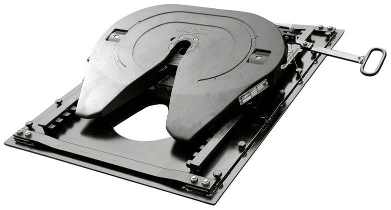
Standard and XXL
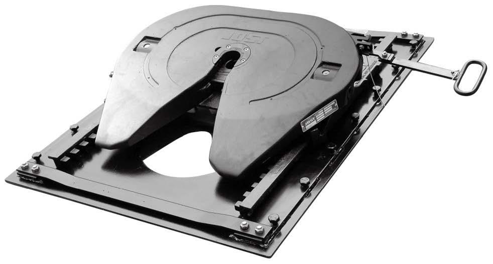
Multi-purpose
• Fifth wheel coupling position freely adjustable in 50mm steps optimum shaft load and load distribution total traction length setting
• Various heights available on request
• Can be attached to all standard vehicle types
• Equipped with the tried and tested fifth wheel couplings JSK37E, JSK37EW
Easy Mounting and operation
• All standard customer hole patterns available ex works
• Easy to mount with a hexagonal bolt
• Base plate to suit European or North American spec chassis
Lightweight, compact and robust
• 25% lighter than its predecessors
• Greater degree of travel with smaller external dimensions
• Cathodic electrophoretic painting for optimum anti corrosion
Top safety standards
• Self-locking mechanism, protected against accidental opening
• Elbow lever principle for greater locking force
• Fourfold, interlocking lock between the carriage and slider frame
• Forged gear tooth rows
• Cast pedestals
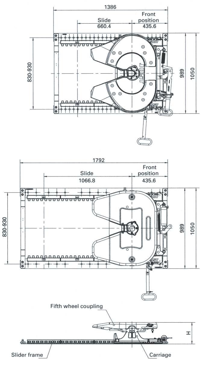
Pos.Description RemarkOrder No.pro JSK
01Fifth wheel coupling * 1
02Split pin ** 2
05Split pin, kit
SLE2022100201
06Bracing, kit SLE2021200201
07Stopper, kit
SLE2025200202
08Lever, kit SLE2023000201
09Cylinder, kit for pneumatic versionSLE2024100201
Spare pedestals are not available
Pos.Description RemarkOrder No.pro JSK
10Traverse, kit
SLE2013800202 10Reinforced Traverse, Kit Scania SLE2013803202 11Bridge, kit for manual versionSLE2027700201 11Bridge, kit for pneumatic version SLE2033000201
*For spare parts for the fth wheel refer to JSK37E
All normal fifth wheel couplings can be mounted on the sliding device. Standard mounting holes for the fifth wheel coupling according to DIN standard 74081 and ISO 3842 are provided.
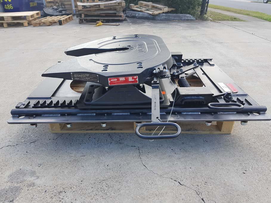
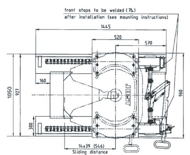
Approval Number
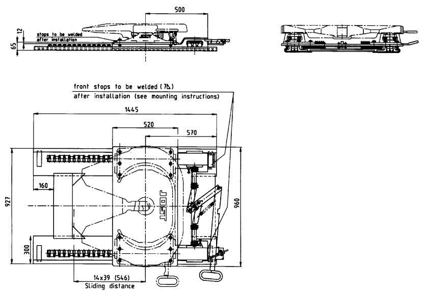
18,000 kg
180-440 kg
Base plate to suit European or North American spec
The above loads apply to operation on ordinary roads and ordinary operating conditions as they are to be found in Europe. If the fifth wheels are being operated in other territories or under other conditions we would ask you to contact us
The right to alter specifications is reserved.
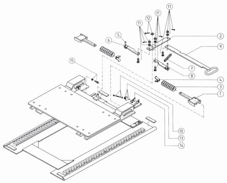
Fig.Description
Part No.
01Locking plunger V100501
02Handle, compl. V100535
03 Spring V100503
04Spring retainer V100504
05 Pin V100505
06 Lever V100548
07Tension spring SK12381
08 Lever V1005139
Fig.Description
09Operating handle
Part No.
V1005183
10Hexagon screw, compl. V102149
11Hexagon screw, compl. V102109
12Washer with split pin V102110
13Spring spacer, clamping sleeves V102150
14Latch, compl. V1005213
15Hexagon screw, compl. V102106
16Slide Upper Part V1002020
All normal fifth wheel couplings can be mounted on the sliding device. Standard mounting holes for the fifth wheel coupling according to DIN standard 74081 and ISO 3842 are provided.
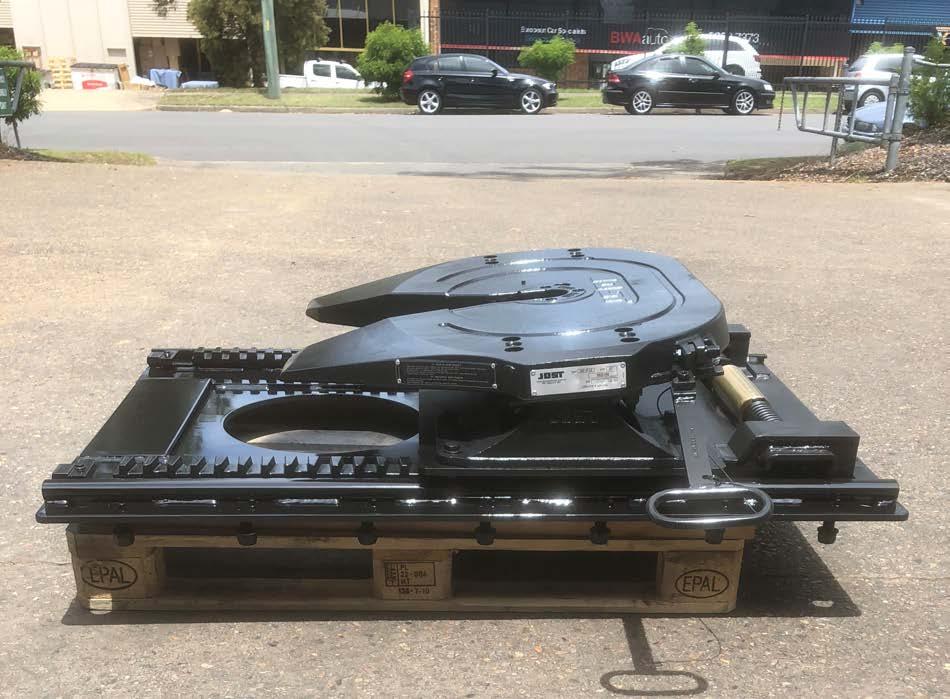
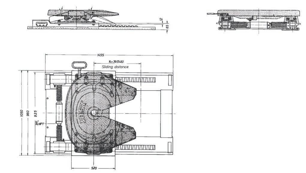
Imposed Load
18,000 kg
Weight approx. 175-435 kg (without fifth wheel)
D-value 190 kN
CRN 26170
Approval Number CTA-026170
For use with JSK37CZ/150
Base plate to suit European or North American spec
The complete pneumatic actuating device (items 9 to 14 of spare parts list shown overleaf) is supplied.
The above loads apply to operation on ordinary roads and ordinary operating conditions as they are to found in Europe. If the fifth wheels are being operated in other territories or under other conditions we would ask you to contact us regarding the type of fifth wheel to be used. The right to alter specifications is reserved.
Fig.Description
01Slider base plate 23"
02Slider upper part
03Locking plunger
04Air-cylinder
V1001006
V100206
V100501
V102105
05Spring V100503
06Spring retainer
V100504
07Pin V100505
08Hexagon screw, compl. V102106
Fig.Description
09Air control valve, compl. V102118
10Fitting
11Fitting
12Fitting
13Pipe plug
14Nylon airline
V102113
V102114
V102115
V102117
V102116
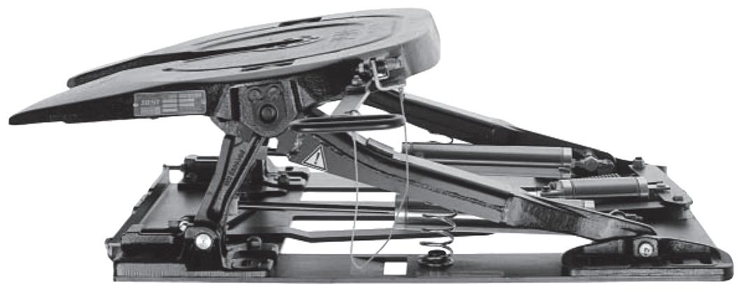
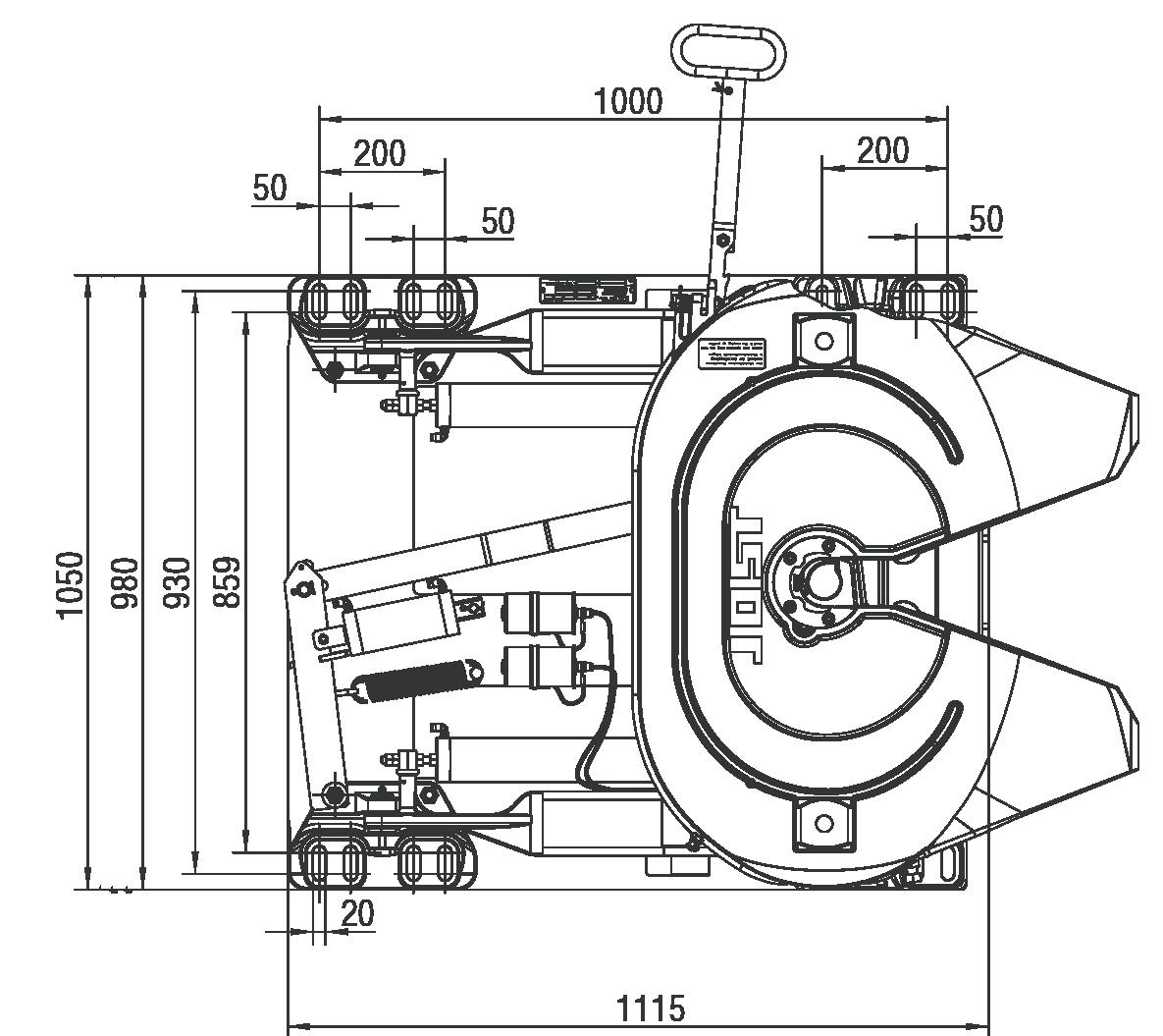
For overheight loads ie. European Containers
Load on main plate 15,000 kg
Weight approx.
kg (with fifth wheel)
D-value
Number
The above loads apply to operation on ordinary roads and ordinary operating conditions as they are to be found in Europe. If the fifth wheels are being operated in other territories or under other conditions we would ask you to contact us regarding the type of fifth wheel to be used.
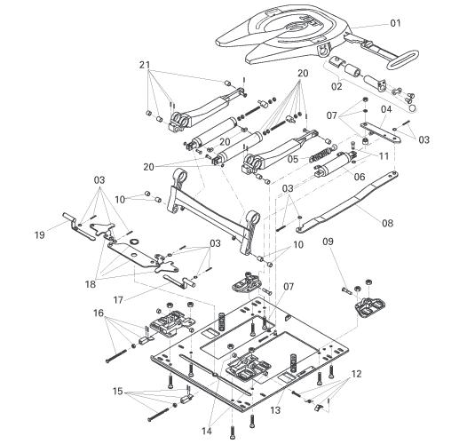
Fig.Description Part No
Fig. Description
Fig.Description
01Fifth wheel coupling
01 Fifth wheel coupling
JSK37E/00128cm
JSK 37 E/00128cm
02Fifth wheel coupling bearing, compl. DH1019902
02 Fifth wheel coupling bearing, comp DH1019902
03 Split pin, complete
DH1019903
03Split pin, complete DH1019903
04 Lever
04Lever
05 Double tension spring
05Double tension spring
06 Closing cylinder
06Closing cylinder
07 Spacer bushing, complete
08 Lever
09 Pivot pin
10 Bushing set 1
11 Bolt complete
DHE1011600
DHE1011600
SK240523
SK240523
DHE1011100
DHE1011100
DH1019907
DH1019908
DH1019909
DH1019910
DHE1003100 Fig. Description
07Spacer bushing, complete
Latch, complete
08Lever
Spring
09Pivot pin
Bushing set 2
10Bushing set 1
DH1019907
DH1019912
DH1019908
DH1019913
DH1019909
DH1019914 15 Wedge right, complete
DH1019915 16 Wedge left, complete
11Bolt complete
DH1019910
DH1019916 17 Locking pin, right
18 Elbow lever
19 Locking pin. left
20 Cylinder, complete
DHE1003100
DH1019917
DH1019918
DH1019919
DH1019920 21 Bushing set 3
DH1019921 22 Paddle
DHPADDLE
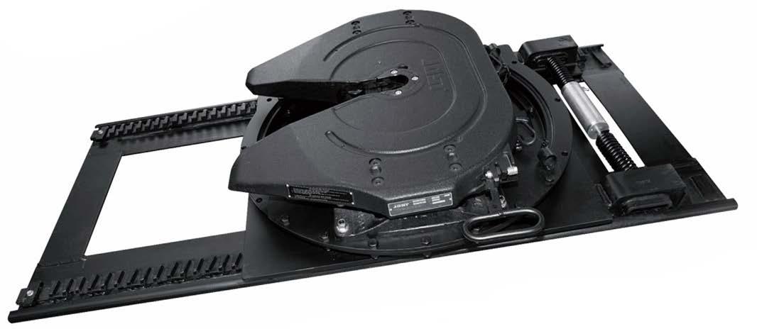
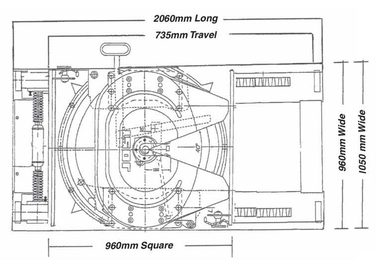
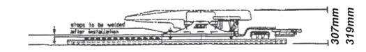
Base Assembly - EVPLP Slider LT Fifth Wheel - JSK37CZ150
• Over 100 kgs lighter than other available products.
• 735 mm of travel.
• Total overall height including the fifth wheel of 307 or 319 mm.
• Total length of 2060 mm.
• Weight: 435-625 kg approx.
• Pneumatically operated.
• CRN’s 24836 and 26170 apply.
• Supplied as standard with the proven tried and tested JSK37CZ Fifth Wheel - “The Industry Standard”.
• Manufactured using only genuine JOST components.
• Imposed Load of 20,000 kgs.
• Will suit all North American and European chassis widths and A-trailers.
2" and 3½" King Pins
2" and 3½" King Pins

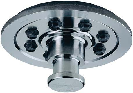
Refer to Jost website www.jostaustralia.com.au for installation and operation instructions.
Until recently precise torque wrenches were not commonly available in workshops and garages. Because of this JOST prescribed onlt torque settings which could not damage the bolts.
The existing torque settings have proven themselves in numerous independent bench tests and in millions of miles of daily use, subject to our installation and maintenance instructions being adhered to.
KZE101203
KZE141603
KZE101606
Nowadays the trailer manufacturers and workshops are using more precise torque wrenches, which are regularly calibrated. This is the prerequisite for a higher torque setting, without the danger of the bolt being damaged. The increase in torque will result in an optimum initial stressing force of the bolt.
The new torque setting will enable the maintenance period to be increased to max. 50,000km resp. six months in line with that of the fifth wheel. The conditions of usage and the instructions of the trailer builders must however be observed.
KZ10081012, KZ1410, KZ1412
KZ1416, KZ2816
KZ1016, KZ1516
Dimensions according to DIN 74080 and ISO 337 JOST king pins can be used in self steering axle systems.
Mounting must be carried out according to the instructions.
Selection table / Versions available
Order No.
Complete
Dimensions according to DIN 74080 and ISO 337 JOST king pins can be used in self steering axle systems.
Mounting must be carried out according to our instructions.
3½" and 2" king pins are easily interchangeable.
Spare Parts for KZ1516
King pin
Retention plate
Self-securing bolt
table / Versions available
3½" & 2" king pins are easily interchangeable
Spare Parts for KZ1016
Dimensions according to DIN 74083 and ISO 4056 JOST king pins can be used in self steering axle systems.
Mounting must be carried out according to our instructions.
Selection table / Versions available
Spare Parts for KZ5216
Dimensions according to DIN 74083 and ISO 4056 JOST king pins can be used in self steering axle systems.
Mounting must be carried out according to our instructions.
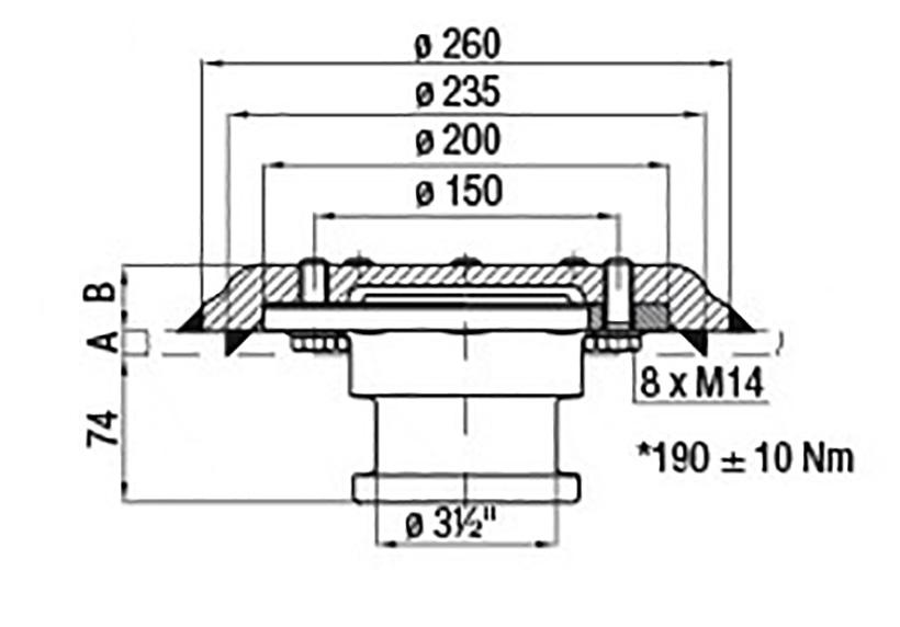
Dimensions according to DIN 74083 and ISO 4086 JOST king pins can be used in self steering axle systems.
Mounting must be carried out according to our instructions.
KZ1412-01
KZ1012-01 3½" and 2" king pins are easily interchangeable.
Parts
Selection table / Versions available
Dimensions according to DIN 74083 and ISO 4086
JOST king pins can be used in self steering axle systems.
Mounting must be carried out according to our instructions
Selection table / Versions available
Spare Parts for KZ2816
Dimensions according to DIN 74080 and ISO 337 JOST king pins can be used in self steering axle systems.
Mounting must be carried out according to our instructions.
Low weight, handy,safe. For all 2" king pins. Completely protects not only the 2” neck, but all mounting bolts. Corrosion-resistant.
Cylinder lock of high quality, dust and water proof. Locking with normal or master keys possible.
Part number: DS2000
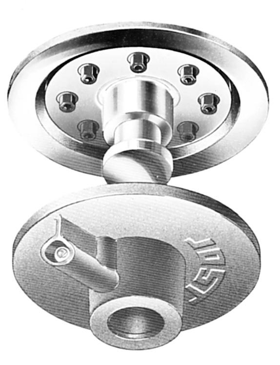
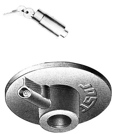
Fig. Description
1 King pin lock, complete
2 Cylinder lock with 2 keys
When reording keys or cylinder locks for locking systems having same keys, please state code number.
Above item is designed as a NO GO wear limit indicator, for either 50mm or 90mm king pins.
Once king pin can pass through gauge the king pin must be replaced. Also designed to check king pin protrusion.
Part number: JOSTGAUGEKINGPIN
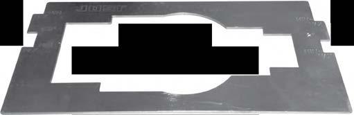
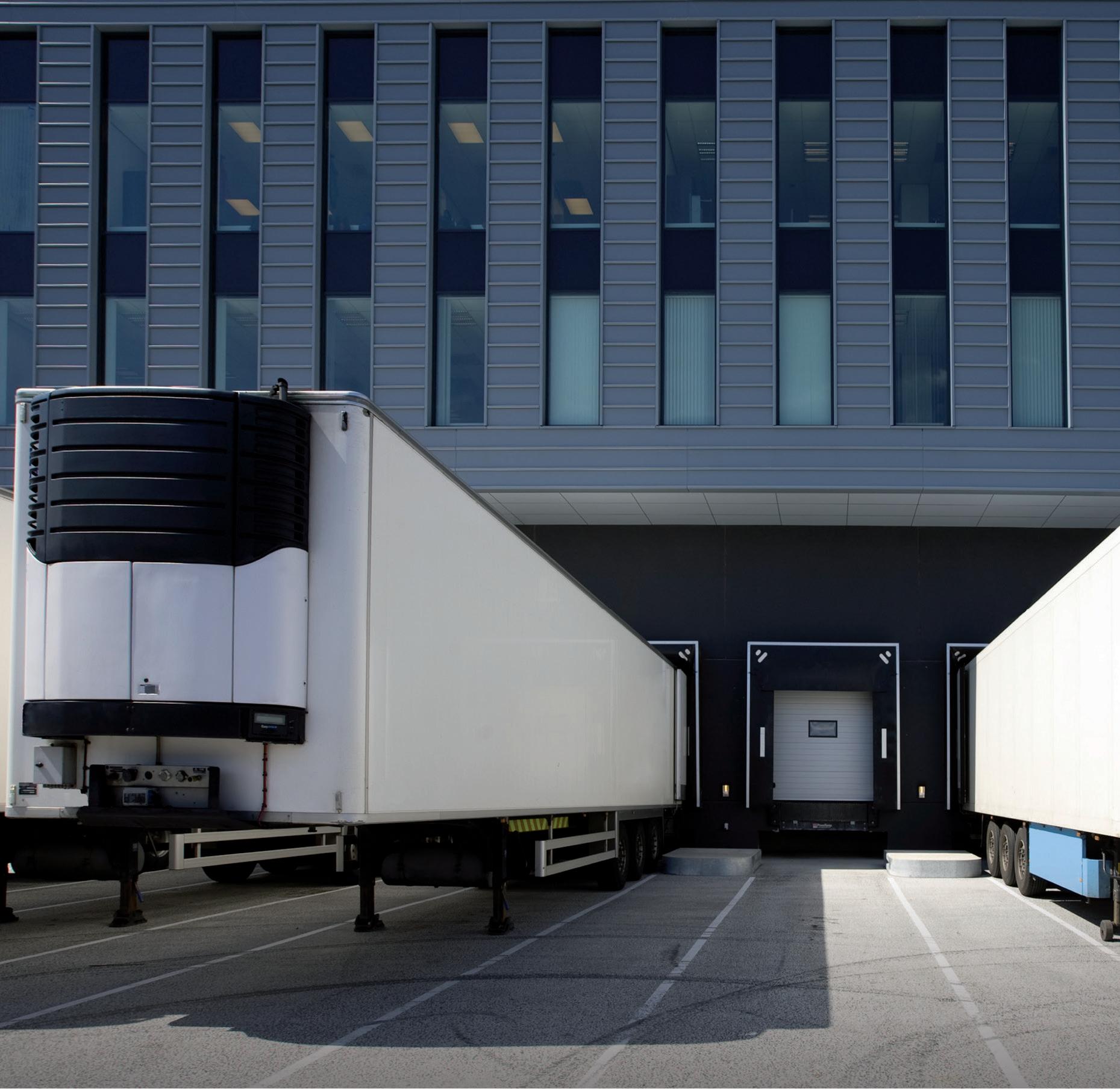
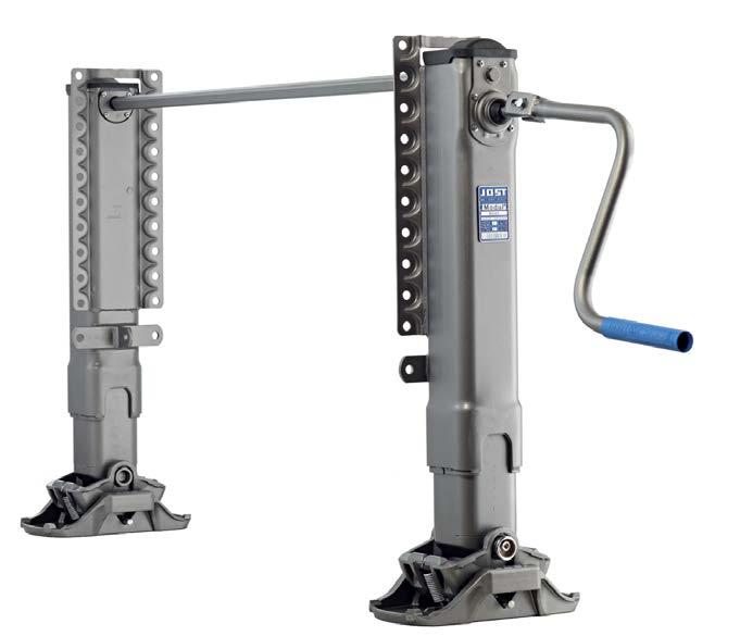
The Modul series of telescopic landing gear is extremely versatile. Thanks to its modular construction with variable mounting and operating heights, various crank handles and connection shaft lengths, plus five different foot types, all client requirements can be met.
Modul B is optimised standard telescopic landing gear. The Modul C range consists of various landing gears which are designed for special applications.
Both ranges offer convincing product advantages: the integrated gearbox has optimum protection, and requires minimum force to be applied on the crank handle in both directions. At the same time, Modul offers an extraordinary increase in lift of up to 120 mm combined with smaller dimensions for fitting. It goes without saying that the telescopic landing gear is extremely sturdy and complies with the strict AAR standard.
The landing gear is not a standalone, functional device. It is designed to be mounted on a trailer. The vehicle may not be operated until it has been ensured that the towed vehicle with the support complies with the applicable national road traffic regulations. In Germany, the relevant “TÜV” Safety Regulations and “StVZO” Motor Vehicle Safety Standards are to be observed. The telescopic landing gear is always to be used in conjunction with the instructions for use issued by the manufacturer of the relevant trailer.
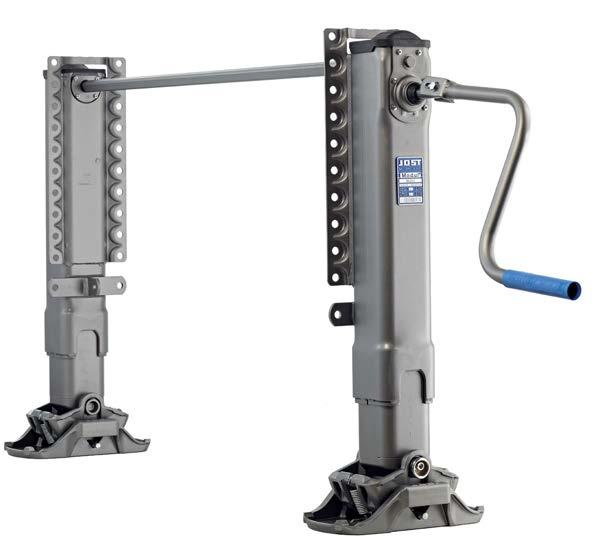
Since the market entrance Modul landing gears are setting benchmarks. The modular construction allows a multitude of different varieties.
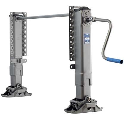
•Easy to assemble and replace foot system
•Greatest flexibility of installation thanks to a range of back plates
•Various crank handles and connection shaft lengths
•Significant gain in lifting force compared to comparable products
•Attractive design
•For universal application
•Type reduction thanks to modular system guarantees high level of flexibility in spare parts business
Patented Modul drive
no neutral gear
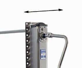
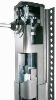
The patented drive is perfectly protected by the internal construction. In addition it offers various advantages in daily use:
•Easy to change between high and low gears
•Very compact construction with high efficiency and extremely low wear
•Large lifting force per turn of the crank with low crank force allows easy and convenient operation
•Reliably secured against run-down
•Maintenance-free
The Modul series of telescopic landing gear are available with a range of different feet: S, A, T and TC foot.
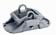
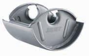
Outstanding corrosion protection
Landing gears from JOST are especially sturdy and resist also unfavorable exterior conditions.
•Careful pre-treatment
•Premium surface through powder coating
•Long-lasting protection against environmental influences and stone chips
The Modul landing gears are equipped with a long-term lubrication. Therefore they can be used three years without relubrication.
•Long-lasting, maintenance-free drive
•No need for subsequent lubrication of our premium stabilisation and aluminium telescopic landing gears with lubrication tube
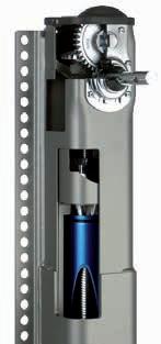
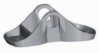
Tested and developed according to internationally recognized standards
•Regular inspection during series production based on the strict AAR standard
•Quality management in accordance with ISO / TS 16949
•Environmental management in accordance with ISO 14001
• 3 year guarantee
Locations worldwide and a broad network of dealers ensure qualified support.
•Competent and individual advice from Sales and Customer Service
•Support for our customers using CAD data during the planning phase
•High level of prevalence and global spare parts supply with short delivery times
• Easy to repair, such as using our foot replacement system
Flexibility due to a modular ordering system
The ordering system allows clients to choose and put together a set of legs to suit their needs.
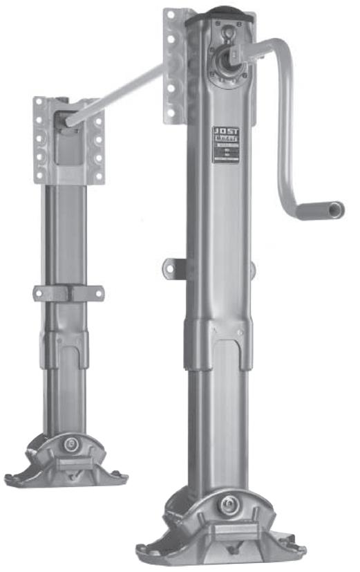
Foot versions
Note: the connection shaft is square
Crank
Subject to change in dimensions and design
Standard with set of legs.
00 = without foot
JSD01 = S Foot compensating foot
JSD02 = A Foot rocking foot
JSD03 = R Foot wheels
JSD04 = T Foot sand shoe
JSD06 = LP T low profile T foot
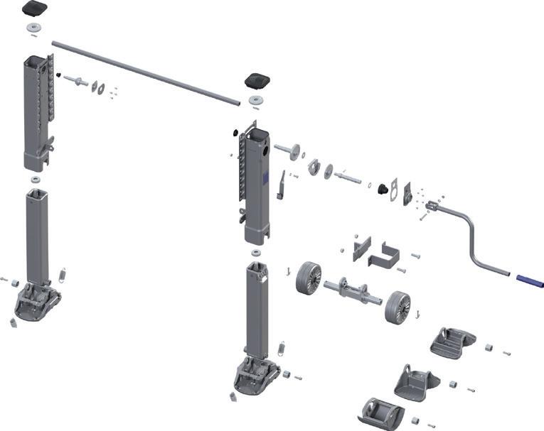
Available in 400mm, 470mm, 520mm
Travel Standard outside flange mounting models
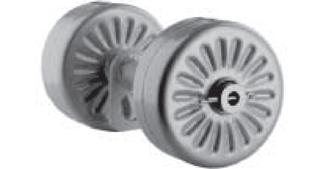
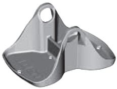
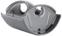
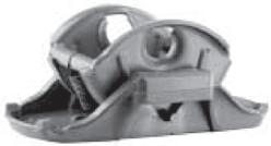
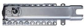
9” Diameter Standard Wheels
9” Diameter Standard Wheels
9” Diameter Standard Wheels
Modul R 400mm
Modul R 470mm
Modul R 520mm
329mm × 230mm Sand Shoes (T Feet)
329mm × 230mm Sand Shoes (T Feet)
329mm × 230mm Sand Shoes (T Feet)
Modul T 400mm
Modul T 470mm
Modul T 520mm
Air Suspension Feet (280mm × 240mm)
Air Suspension Feet (280mm × 240mm)
Air Suspension Feet (280mm × 240mm)
Modul A 400mm
Modul A 470mm
Modul A 520mm
Compensating Feet (397mm × 260mm)
Compensating Feet (397mm × 260mm)
Compensating Feet (397mm × 260mm)
Modul S 400mm
Modul S 470mm
Modul S 520mm
Supplied without Feet can take R.T.S or A Feet
Supplied without Feet can take R.T.S or A Feet
Supplied without Feet can take R.T.S or A Feet
Modul WF 400mm
Modul WF 470mm
Modul WF 520mm
Note: Inside flange mounting models also available
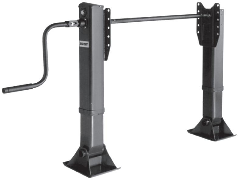
Landing Gear Dimensions - Outside Mount
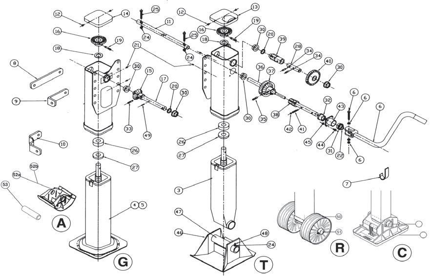
Mounting instructions
Before mounting, both jacks must be in retracted position, in order to take advantage of the total stroke after mounting connection shaft and to avoid premature ground touch of one jack. Otherwise one single jack would have to carry the total load, causing damage.
The jacks must be mounted parallel and properly aligned, otherwise the connection shaft could tilt and make the landing gear hard to operate.
Fitting and bracing should be carried out as shown below.
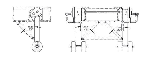
The introduction of air suspension on semi-trailers has resulted in an increase of related problems.
When the semi-trailer has been standing for a considerable time a loss of air in the suspension is liable to occur, causing the rear part of the trailer to sink down.
This in turn results in an angular movement of the axle, forcing the trailer in the direction of travel if the brakes are on. This movement depends on the type of air suspension, the spring deflection and the size of the tyres.
The larger the drift and the greater the force the greater is the chance of the landing gear being subjected to a force with which it cannot cope, ultimately resulting in it being bent. This damage is a secondary consequence of the loss of air.
This can be avoided by using landing gear with drift compensation.
The JOST “A” foot is a semi-wheel which is able to compensate for the entire movement of the trailer and remove the force of drift from the landing gear.
A paved surface is essential for the correct function of this version.
A further variation is the JOST “S” foot. The large sand shoe cannot sink in and can therefore also be used on an unpaved surface.
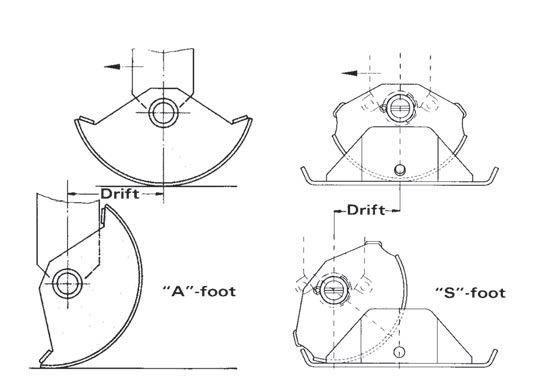
Uncoupling:
1. Block wheels of semi-trailer.
2. Unlock and engage crank handle.
3. Wind down landing gear in high gear until ground is touched.
4. Shift to low gear position by pushing the crank handle towards the gear box for MODUL legs, pull he crank handle out to select low gear for A400 and E110 legs an lift to necessary height.
Caution: Stop cranking when end of travel is reached.
Coupling-up:
1. After locking the fifth wheel wind-in landing gear in low gear until inner leg has left the ground.
2. Shift to high gear by pulling the crank handle and wind-in inner leg.
Caution: Stop cranking when end of travel is reached.
3. Fasten crank handle in holder, making sure that high gear is still engaged.
The landing gear received adequate initial lubrication during manufacture. Relubrication is possible through grease nipples provided.
The spindle is lubricated with BP grease JS12 by the lower of the two grease nipples located on the side of the housing. Prior to lubrication wind down the landing leg as far as possible and during lubrication slowly wind it up. For subsequent lubrication of the other greasing points we recommend the use of high pressure grease (EP) with MoS, or graphite additive, for example:
BP L2 1M
BP HT-EP 1
BP JSS2
Esso universal grease M
Shell Retinax AM
When inspecting the trailer, all parts which are subject to wear must be checked and replaced if necessary.
These instructions are based on normal conditions of use. In the case of difficult operating conditions the maintenance and lubrication intervals must be reduced accordingly.

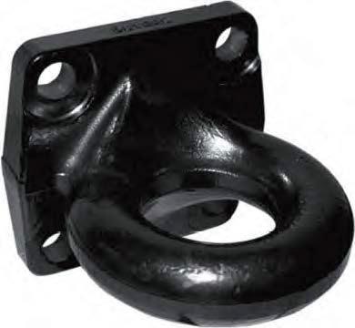
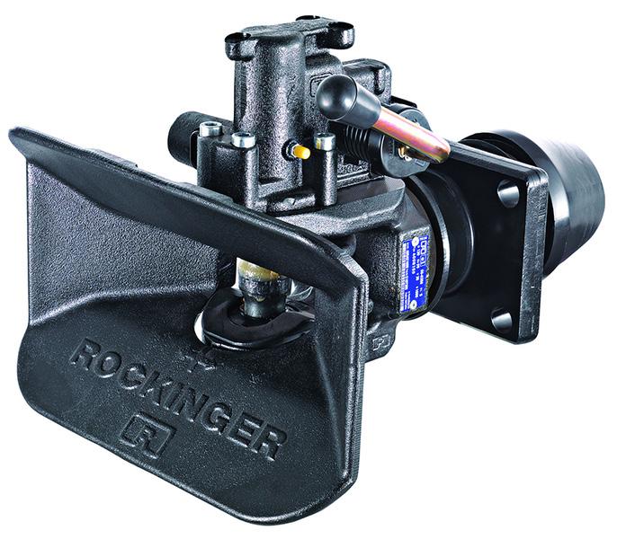
Towing eyes according to DIN 74054-40A pressed-in replaceable towing eye sleeve 40 mm inner diameter
Part number
ROE57374
D-value 125kN
Weight 5kgs
Down load 250kgs
Approval Number ECE E1 55R-01 2203
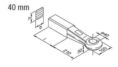
Towing eyes according to DIN 74053 pressed-in replaceable towing eye sleeve 50 mm inner diameter
Part no.
ROE57272
Material: heat-treated steel St 52-3
D-value: 190 kN
Weight: 10.3 kgs
Down Load: 1000 kgs
Approval Number ECE E1 55R-01 2335
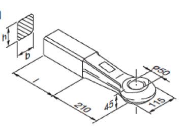
ROE57005 c/w solid bush
Part no.
ROE57005
Material: heat-treated steel St 52-3
D-value: 314kN
Weight: 13.4 kgs
Down Load: 1000 kgs
D-value is reduced to 190kN with 100 kgs down load.
Approval Number ECE E1 55R-01 2146
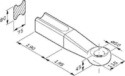
Tow eye 8 bolt flange mount 50mm inner diameter
Part number ROE57244
D-Value 190kN
S-Value 2500kgs
V-Value 43.2kgs
Approval Number E1 SSR-01 0045
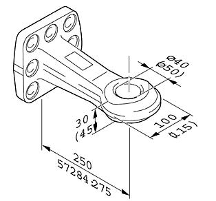
ROE70304
Flange mount tow eye backing plate including bolts
Part number ROE70304
a
Part no: ROE70950 - Bolt kit if required separately
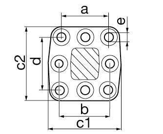
Part no: JOST 57254
D-Value: 260 kN
Weight: 18,5 kg CRN: 42292
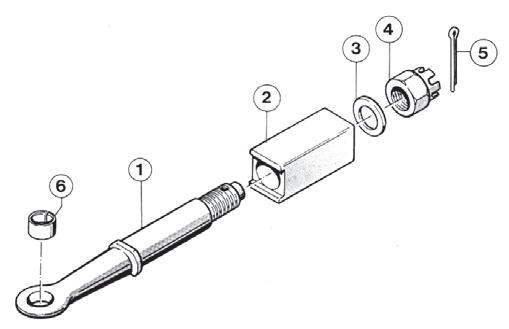
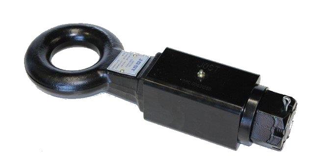
Part no. BPCBDB1394
Model: 45-Ton Forged Heavy Duty Towing Eye
Description: Finished with black powder coat for superior durability and corrosion resistance.
D-Value: 165kn
CRN: 37264
Dimensions: 3" I.D. with 1.62" section drawbar with 4 hole square mounting plate.
Part no: JOST0063126
Model 76mm Demountable Pintle Eye
D Value 125kN
V Value 7 Tonne
ATM 25 Tonne
CRN 41615
Eye Dimension 76.5mm
Shank Dimension 50mm
Block Dimension 90x90x150mm
Total length 435mm
Features:
1. 10mm thick top and bottom plate, case hardened.
2. No padlock, uses highly developed Super Lock Bolt, 25.4mm diameter, case hardened body. Anti drill centre pin, 10 pin radial pin tumbler lock insert with over 1 million possible key combinations.
3. Easy to operate, only the lock bolt needs to be removed to unlock trailer.
4. Lock bolt can only be locked/unlocked using key, no accidental locking possible.
5. Dust cap provided to prevent ingress of dust and dirt into lock.
6. Finished in highly visible, yellow powder coating.
7. 2 keys supplied with lock as standard. Multiple locks can be supplied with same key for fleet or multi user applications.
8. Independantly tested and approved by SCM. Approval No. MP030417.
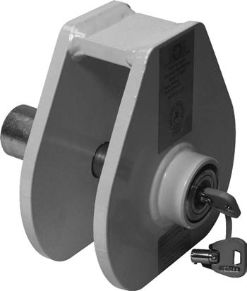
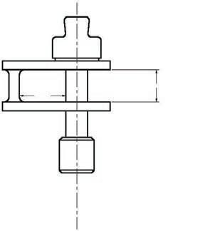
1. Rockinger drawbar eyes are provided for welding into the drawbar by electric arc welding, preferably done under a protective gas shield.
2. The steel of the drawbar has to be weldable, e.g. made of St 37-2 or St 52-3 or any other compatible weldable steel with a carbon content of less than 0.22%.
3. Remove all paint, grease and rust from welding surfaces. Heating up of drawbar eye to 200 - 250°C before beginning to weld is recommended.
4. The drawbar eye must not be welded within a length of *mm measured from the middle of the drawbar eye access towards the back. This part should protrude out of the drawbar.
5. The welding should be exercised in one seam at a time only, in order to avoid overheating the surrounding space of the welding seam.
6. Carry the welding onwards to the direction of the drawbar eye access in one procedure.
7. All seams have to be layed in longitudinal direction of the drawbar eye’s shaft. Never and by no means crosswire.
8. Each seam of welding should be set one by one diagonally opposite to the last one, so you maintain an even radiation of heat.
9. Cooling down of the welding should take place where the air is still; do not immerse into water or pour water over it.
10. If wanted, you can place slot welds through the lateral surface of the drawbar’s sectional steel. This is in order to fix the drawbar shaft to the drawbar additionally.
11. The thickness of the welding seams is to be approximately 8mm in full V- shape or half V-shape.
12. The thickness of the sectional connecting bars should be atleast 8mm, better from 10mm - 12mm.
57268DIN
57262DIN
57260DIN
57272DIN + ISO
57254 Rockinger for 56, 561 and 702
65 × 55 ∅ 40mm = 210mm
50 × 40 ∅ 40mm = 210mm
40 × 40 ∅ 40mm = 210mm
65 × 60 ∅ 50mm = 210mm
50mm = 195mm
57006 ring 41 strong, NATO ∅ 76mm = 180mm
• Hole pattern in the crossbar of the towing vehicle
• Hole pattern in the coupling flange
• Pin size of the coupling
Truck and trailer: D-value
• Theoretical horizontal force between towing vehicle and trailer
• The D-value can only be calculated with the permissible total weight of both truck and trailer.
• Calculation of the D-value [kN] with formula 1 (F1):
T : Total weight of the towing vehicle in t
R : total weight of the drawbar trailer in t
g : Gravitation acceleration 9,81 m/s²
The calculated D-value can be equal to or lower than the D-value of the coupling and of the drawbar eye.
In case of mounting on a trailer is permitted use formula 2 (F2):
R1 : Total weight of trailer where the coupling is mounted (max. 24 t) R1 ≥ R2
• Values of the coupling
• Values of towing vehicle and trailer (see vehicle registration certificate)
• Values of the drawbar eye
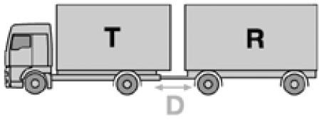
Towing vehicle and central-axle trailer: Dc-value (Valid only in connection with the V-value
• Theoretical horizontal force between towing vehicle and trailer
• The Dc-value can only be calculated with the permissible total weight of both towing vehicle and central-axle trailer.
• Calculation of the Dc-value with formula 3 (F3):
T : Total weight of the towing vehicle in t
C : Sum of the axle loads of the central-axle trailer in t
g : Gravitation acceleration 9,81 m/s²
The calculated Dc-value can be equal to or lower than the Dc-value of the coupling and of the drawbar eye.
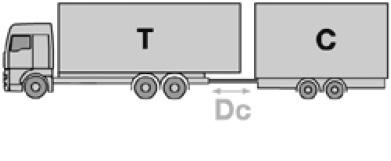
trailer: V-value (Valid only in connection with the Dc-value)
• Vertical force for central-axle trailer
• Dependent on the rear axle suspension of the towing vehicle.
• Calculation of the V-value [kN] with formula 4 (F4):
a : An equivalent verticle acceleration in the coupling point in m/s² (a = 1, 8 for vehicles with air suspension/ a = 2, 4 for vehicles with other suspensions)
I : Theoretical drawbar length in meters
x : Length of the loading area in meters (x²/I² : atleast 1, 0)
C : Sum of the axle loads of the central-axle trailer in t
The calculated V-value can be equal to or lower than the V-value of the coupling and of the draw- bar eye.
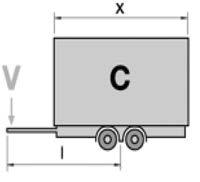
trailer: Static vertical load (Valid only in connection with the V-value)
• Vertical load of the central-axle trailer on the coupling point.
• The vertical load depends on the size of the coupling and the maximum is 10% of the gross weight of the trailer or 1000kg (whichever is less).
• When using a central-axle trailer the vertical load should amount to at 4% of the trailer weight in order to prevent increased wear caused by bouncing of the drawbar eye.
Standardkupplung
Standard hitch
Crochet standard
Standard hitch
Gancio di traino standard Enganche estándar
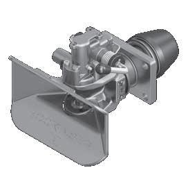
Technical Data
Technische Daten • Technical data • Données technique • Dati tecnici • Datos técnicos
S (kg)V (kN)(kg) Dc (kN) (mm)D (kN)
RO400A36001135120x557070,070024,030,001035270970
RO400A36001135120x557070,050026,430,001035270970
RO400B36001135120x557070,070024,030,001035270970
RO400B36001135120x557070,050026,430,001035270970
RO400A46001145140x8010091,5100031,233,001035170952
RO400B46001145140x8010091,5100031,233,001035170952
RO400A51001150160x10013090,0100035,035,001035070971
RO400B51001150160x10013090,0100035,035,001035070971
RO400A51201150160x10013090,0100035,035,0010350x70971
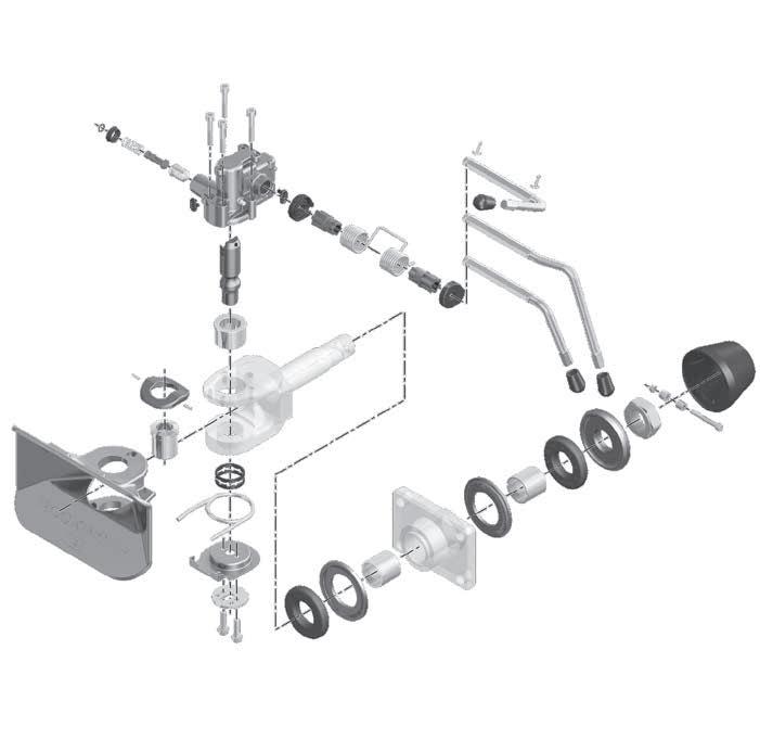
kein Ersatzteil no spare part non pièce de rechange no ricambio no es pieza de recambio No spare part
G145/150ROE716401 14G135ROE252541
G145/150ROE253471 15G135ROE716411
G145/150ROE717961 16G145/150ROE592801 G135ROE592791 17G135ROE441601 G145/150ROE441611
Vollautomatische Anhängekupplung
Fully automatic towing hitch
Crochet d’attelage entièrement automatique
Gancio di traino automatico
Fully automatic towing hitch
Enganche para remolque totalmente automático
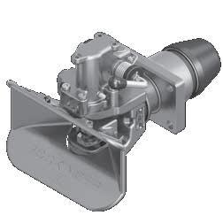
Technische Daten • Technical data • Données technique • Dati tecnici • Datos técnicos
RO500A66000 A 6160x10020014010009050011844
RO500A66000 A 6160x10020014025006050011844
RO500B66000 B 6160x10020014010009050,5011844
RO500B66000 B 6160x10020014025006050,5011844
RO500A66200 A 6160x10020014010009050011844x
RO500A66200 A 6160x10020014025006050011844x
RO500A66400 A 6160x10020014010009050011844xx
RO500A66400 A 6160x10020014025006050011844xx
RO500A66550 A 6160x10020014025006050011844xx
RO500A66550 A 6160x10020014010009050011844xx
RO500A66500 A 6160x10028514025006050011844
RO500A66500 A 6160x10028514010009050011844
RO500B66500 B 6160x10028514025006050,5011844
RO500B66500 B 6160x10028514010009050,5011844
RO500A66570 A 6160x10020014010009056,5011844xx
RO500A66570 A 6160x10020014025006056,5011844xx

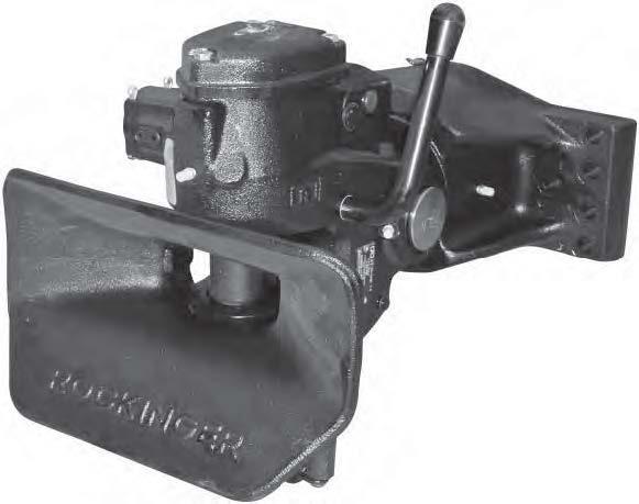
50mm fully automatic trailer coupling
Heavy duty coupling for highway and off road
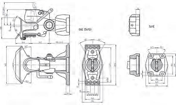
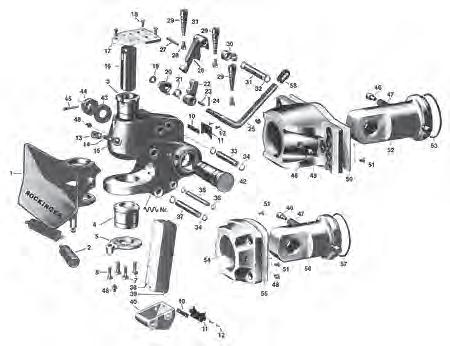
04, 16, 21, 24, 32, 34, 34-1, 35, 36, 39, 42, 44, 45, 48, 48-1, 48-2, 49, 54
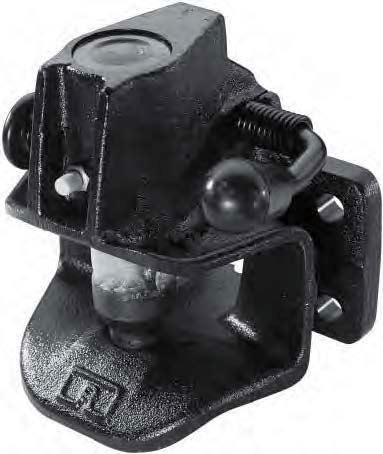
¹ s. p. 14
² diagonal
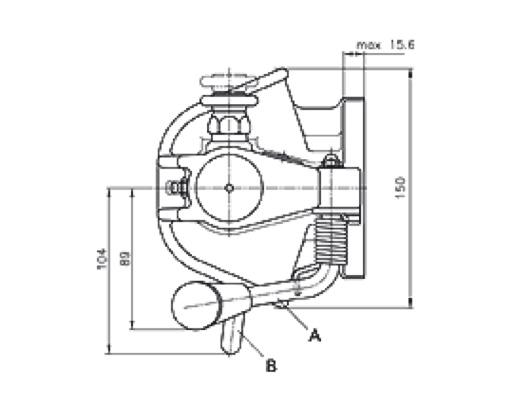
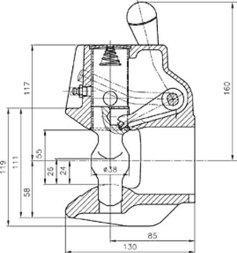
Also for industrial trucks (transport carts, fork lift trucks, etc.) with maximum total weight up to 5t and maximum towed load up to 20t (without vertical load only for inside-factory transport).
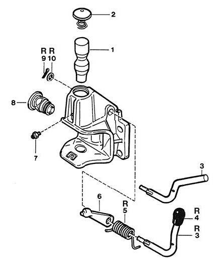
Gefederte Hakenkupplung mit Sicherheitsklinkenverschluss
Hook trailer hitch with buffers and safety lock
Gefederte Hakenkupplung mit Sicherheitsklinkenverschluss
Accouplement à crochet suspendu avec verrouillage à contrecliquet
Hook trailer hitch with buffers and safety lock
Gancio a uncino oscillante con spinotto di sicurezza
Hook trailer hitch with buffers and safety lock
Technische Daten • Technical data • Données technique • Dati tecnici • Datos técnicos 76mmAnhängekupplungen•76mmTowinghitches•76mmCrochetsd’attelages•76mmGancidiTraino•76mmEnganchespararemolque
Accouplement à crochet suspendu avec verrouillage à contrecliquet
Enganche de gancho con cierre de pestillo de seguridad
Gancio a uncino oscillante con spinotto di sicurezza
Enganche de gancho con cierre de pestillo de seguridad
a = 76 mm VG 74059 NATO
14588180156410 15088180156424
135120,055,0155,090,015,074,0
145140,080,0180,0120,017,084,0 150160,0100,0200,0140,021,094,0
135120,055,0155,090,015,074,0
145140,080,0180,0120,017,084,0
150160,0100,0200,0140,021,094,0
Technische Daten • Technical data • Données technique • Dati tecnici • Datos técnicos
S (kg)V (kN)C (t)R (t)(kg) Dc
RO283A35002135120x557042,580015,66,51617,7
RO283A45002145140x809554,0100021,69,03022,7
Technical data
RO283A50002150160x10016054,0150021,69,04031,0
RO283A35002135120x557042,580015,66,51617,7
RO283A50092150160x10016054,0150021,69,04031,0
RO283A45002145140x809554,0100021,69,03022,7
RO283A50002150160x10016054,0150021,69,04031,0
Order no. Size
RO283A50092150160x10016054,0150021,69,04031,0
No spare part Fig. Description
01 135, 145 ROE66393
02 135, 145 ROE52036 02 283xxxxx2 ROE52037 03 ROE56030
04 283A35xx1 ROE71606 04 283Axxxxx ROE70285 05 135 ROE70343 05 283A45xx0 ROE70344
05 283A45/50xx2
H kein Ersatzteil no spare part non pièce de rechange no ricambio no es pieza de recambio
ROE70344
06 135 ROE44060
06 145, 150 ROE44134 07 283A50xx2 ROE59280 08 283A45/50xx2 ROE71796
09 283xxxxx2 ROE30492
10 135 ROE56051
10 145, 150 ROE56049 10 283A45/50xx2 ROE25347
09283xxxxx2ROE304921 10135ROE560511 10145,150ROE560491 10283A45/50xx2ROE253471
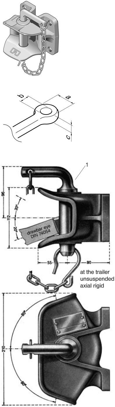
• Non-automatic trailer coupling with flange bearing hole pattern: 120mm × 55mm
¹ D-value
² Statical vertical load
• Usable on agricultural trailers only (R)(p.e. R¹ = 16t; R² = 10t)
• Admissible total weight of a vehicle combination of 40t
Dimensions of the coupling
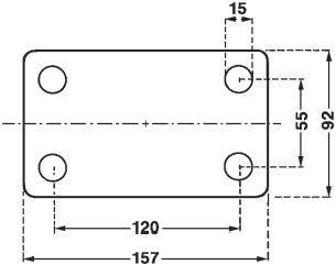
Spare parts for series RO*805B
Compact hitch for industrial trucks and trailers
Kompaktkupplung für Flurförderzeuge und deren Anhänger
Compact hitch for industrial trucks and trailers Crochet d’attelage compact pour chariots de manutention et leurs Gancio compatto per adibiti a movimentazione interna con relativi Enganche compacto para vehículos industriales y sus remolques
Anhängekupplungen•40mmTowinghitches•40mmCrochetsd´attelages•40mmGancidiTraino•40mmEnganchespararemolque
Kompaktkupplung für Flurförderzeuge und deren Anhänger
Compact hitch for industrial trucks and trailers
Crochet d’attelage compact pour chariots de manutention et leurs remorques
Gancio compatto per adibiti a movimentazione interna con relativi rimorchi
Enganche compacto para vehículos industriales y sus remolques
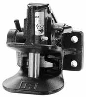
Zugöse, for drawbar eye, pour anneaux, per occhioni, para puntas:
DIN 74054
2) DIN 8454
3) CUNA 438/40
Für Zugöse, for drawbar eye, pour anneaux, per occhioni, para puntas:
1) DIN 74054
2) DIN 8454
1) Zugösen • Towing eyes • Anneaux de remorquage • Occhionei di 2) Zugösen • Towing eyes • Anneaux de remorquage • Occhionei di 3) Zugösen • Towing eyes • Anneaux de remorquage • Occhionei di
(mm)D (kN)
Zugösen • Towing eyes • Anneaux de remorquage • Occhionei di traino • Puntas de lanza (DIN 74054)
RO244A07002 A 07130x3042
Zugösen • Towing eyes • Anneaux de remorquage • Occhionei di traino • Puntas de lanza (DIN 8454)
RO244A11002 A 11583x5642
Zugösen • Towing eyes • Anneaux de remorquage • Occhionei di traino • Puntas de lanza (CUNA 438/40)
RO244A35002 A 135120x5542
Size model a (mm) b (mm) c (mm) d (mm) e (mm) 135 120 55 155 90 15
1) Zugösen • Towing eyes • Anneaux de remorquage
S (kg)V (kN)(kg) Dc (kN) (mm)D (kN)
Technische Daten • Technical data • Données technique b a e (4x)
2) Zugösen • Towing eyes • Anneaux de remorquage
3) Zugösen • Towing eyes • Anneaux de remorquage Für Zugöse, for drawbar eye, pour anneaux, per
244A07002 A 07130x3042302508,46011803
244A11002 A 11583x5642302508,46011804
244A35002 A 135120x5542302508,46011802
Choice of the coupling
tractor bearing of the coupling
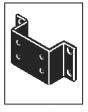
1. flange bearing
1. Hole pattern at rear tractor: coupling with flange bearing and corresponding hole pattern
2.1 lift bearing
2. Coupling holder of tractor
2.1 Coupling with lift bearing
2.2 Coupling with insert pin bearing
2.2 insert pin bearing
Calculation
1. total vehicle combination weight
Admissible total vehicle combination weight: currently 40t.
2. towed load
In absence of D-value specification:
Admissible total vehicle combination weight (currently 40t) minus admissible total weight of tractor
3. D-value
D-value (not for all couplings)
Theoretical horizontal force between towing vehicle and trailer; comparative mathematical value of forces between moving masses.
The D-value can only be calculated with the permissible total weight of both truck and trailer.
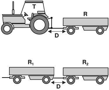
Calculation of the D-value (kN):
T : total weight of the towing vehicle in t R : total weight of the turnable trailer in t g : gravitation acceleration (9,81 m/s²)
The calculated D-value can be equal to or lower than the D-value
D = g ∙ R1 ∙ R2 R1 + R2
R1 : total weight of trailer where the coupling is mounted (in t)
R1 ≥ R2
3. Static verticle load
• vertical load of the central-axle trailer on the coupling point
• The vertical load depends on the size of the coupling and the maximum is 10% of the gross weight of the trailer or 1000kg (whichever is less).
• When using a central-axle trailer the vertical load should amount to at 4% of the trailer weight in order to increased wear caused by bouncing of the drawbar eye.
• Size of static vertical load is also a function of speed.
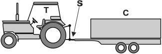
Central-axle trailer (C): Use admissible in principle:
• size of central-axle trailer depends on characteristics of drawbar eye and tractor unit
• please see table for restrictions
Couplings and drawbar eyes for the road traffic which have been verified according to european standard specification 94/20 have special fixed identying sizes, the Dc-value and the V-value, for the operation with the central-axle trailer.
These values are not of importance in the agriculture and forestry. Since the Dc-value and the V-value are indicated with some of the following mentioned drawbar eyes, these sizes are briefly explained.
Towing vehicle and central-axle trailer
Dc-value
(valid only in connection with the V-value)
• theoretical horizontal force between towing vehicle and trailer.
• The Dc-value can only be calculated with the permissible total weight of both towing vehicle and central-axle trailer.
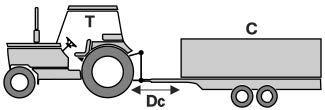
• Calculation of the Dc-value (kN):
T : total weight of the towing vehicle in t
C : sum of the axle loads of the central-axle trailer.
g : gravitation acceleration 9,81 m/s²
The calculated Dc-value can be equal to or lower than the Dc-value of the drawbar eye.
Central-axle trailer: V-value
(valid only in connection with the Dc-value)
• vertical force for central-axle trailer.
• dependent on the rear axle suspension of the towing vehicle
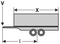
• Calculation of the V-value (kN):
a : an equivalent vertical acceleration in the coupling point in m/s²
a = 1,8 for vehicles with air suspension
a = 2,4 for vehicles with other suspensions l: theoretical drawbar length in meters
x : length of the loading area in meters x² / l²: atleast 1,0
C: sum of the axle loads of the central-axle trailer in t
The calculated V-value can be equal to or lower than the V-value of the drawbar eye.
BPCBH850MM (8 Ton)
Capacity
3,000 lbs. maximum vertical load
16,000 lbs. M.G.T.W.
Description
Drop forged combination pintle hook/ball hitch. Forged steel ball. Interchangeable hitch balls. Finished with black powder coat for durability and corrosion resistance.
Drawbar Eye Dimensions
2½" to 3" up to 19⁄16 cross section. Hitches are shipped with drilling template, capacity decal, and are individually boxed.
Weight 13 lbs
37265
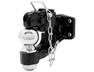
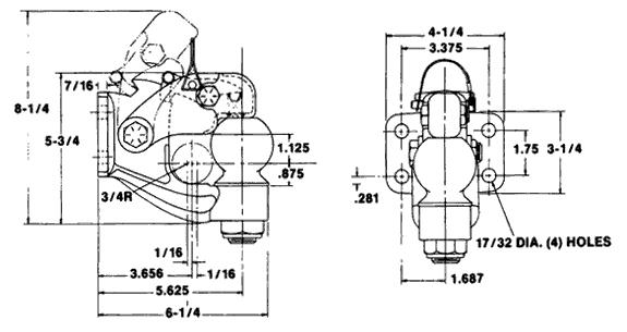
& BPCPAC4BK (45 Ton) - BPCP45AC6 & BPCPAC6BK (45 Ton)
Buyers Pintle Hooks feature a “double-safe” locking system with a lock/ clasp/impact arm interacting design that combine to prevent release of the eye when air pressure is applied. The Air Compensated Pintle Hooks must be used with a brake chamber.
The air brake chamber is constructed to interact with the closed clasp to prevent uncoupling when air is applied.
P45AC4 is to be used with a lunette eye having an internal diameter between 2³⁄8" and 3", and a material cross section between 1¼" and 1¾" in diameter.
P45AC6 is to be used with a lunette eye having an internal diameter between 2³⁄8" and 25⁄8", and a material cross section between 15⁄8" and 1¾" in diameter.
Weight: BPC P 45 AC4 26lbs
Weight: BPC P 45 AC4BK 3.2lbs CRN 37266
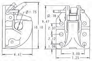
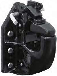
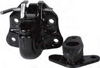
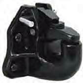
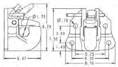
BPCPH15WMK (15 Ton)
Capacity
6,000 lbs. maximum vertical load
30,000 lbs. M.G.T.W.
Description
Drop forged alloy steel rigid type pintle hook. Finished with black powder coat for superior durability and corrosion resistance.
Drawbar Eye Dimensions
2" to 3" I.D. with 1¼" to 15⁄8" diameter section.
Pintle hooks are individually boxed and include mounting information sheet, spec. sheet, adhesive backed drilling template, and vehicle capacity decal.
Weight 11.75lbs
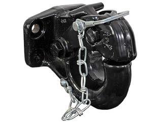
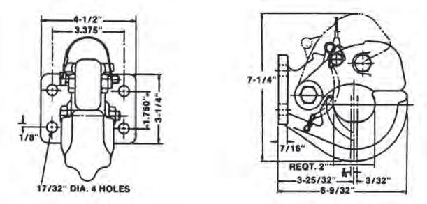
BPCPH20WMK (20 Ton)
Capacity
8,000 lbs. maximum vertical load
40,000 lbs. M.G.T.W.
Description
Drop forged alloy steel rigid type pintle hook. Finished with black powder coat for superior durability and corrosion resistance.
Drawbar Eye Dimensions
2" to 3" I.D. with 1¼" to 15⁄8" diameter section.
Pintle hooks are individually boxed and include mounting instructions, specifications sheet, adhesive backed drilling template, and vehicle capacity decal.
Weight
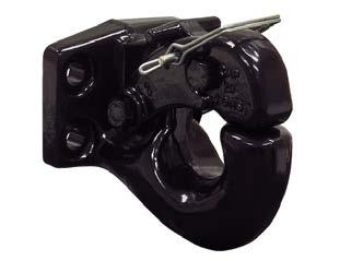
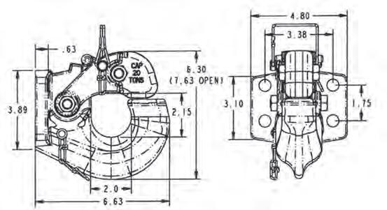
Capacity
15,000 lbs. maximum vertical load
60,000 lbs. M.G.T.W.
Description
Drop forged alloy steel rigid type pintle hook. Designed for ease of use, long life and corrosion resistance.
Drawbar Eye Dimensions
2" to 3" I.D. with 1¼" to 15⁄8" diameter section.
Pintle hooks are individually boxed and include mounting instructions, specification sheet, adhesive backed drilling template and vehicle capacity decal.
Weight 24lbs
44894
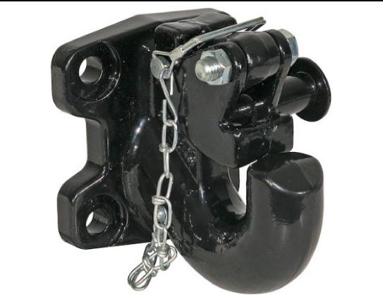
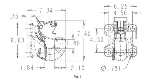
Capacity
20,000 lbs. maximum vertical load
100,000 lbs. M.G.T.W.
Description
50 Ton air compensated pintle hook reduces wear and absorbs shock in heavy duty towing situation.
Drawbar Eye Dimensions
2.38" to 3" I.D. with 1¼" to 15⁄8" diameter section.
Pintle hooks are individually boxed and include mounting instructions, specification sheet, adhesive backed drilling template, and vehicle capacity decal.
Weight 44.8lbs
45107
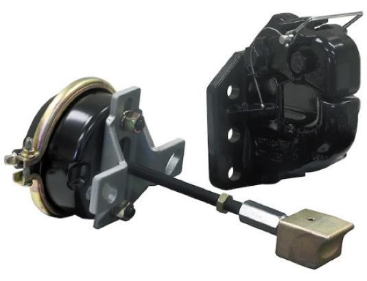
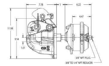
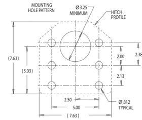
Part Number: BPCPM87
Capacity:
2800lb: maximum vertical load 14000lb :M.G.T.W.
Description: Pintle Hook 8 hole mount
Weight: 15lb
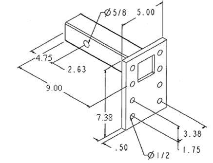
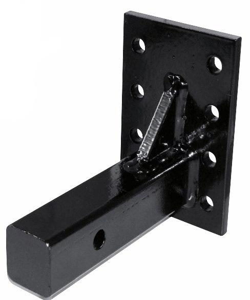
Part Number: BPCPM84
Capacity:
4000lb: maximum vertical load
20000lb :M.G.T.W.
Description: Pintle Hook 4 hole mount
Weight: 12lb
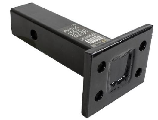


JOST HUBODOMETER is a precision instrument for all kinds of wheeled vehicles, e.g. semi-trailers trailers low-bed trailers buses trains and other equipment.
JOST HUBODOMETER will record information for maintenance schedules wear and tear controls mileage of leasing vehicles exact data for calculation of transport costs validating guarantees
Smallest dimension
Overall depth only 23 mm
Mounting
Directly to the wheel cap or shockproof mounting in a special wheel cap
Recording mechanism
Completely and permanently sealed. Filled with inert gas against fogging and ingress of moisture or dirt. Records forward and reverse motion. Completely tamperproof.
Records up to one million miles. Records in kilometres or miles. All parts corrosion resistant.
Weight: 0.24 kg
3 Year or 500,000kms warranty, whichever comes first.
When ordering please state:
1. exact tyre size resp. circumference
2. calibration for kilometres or miles.
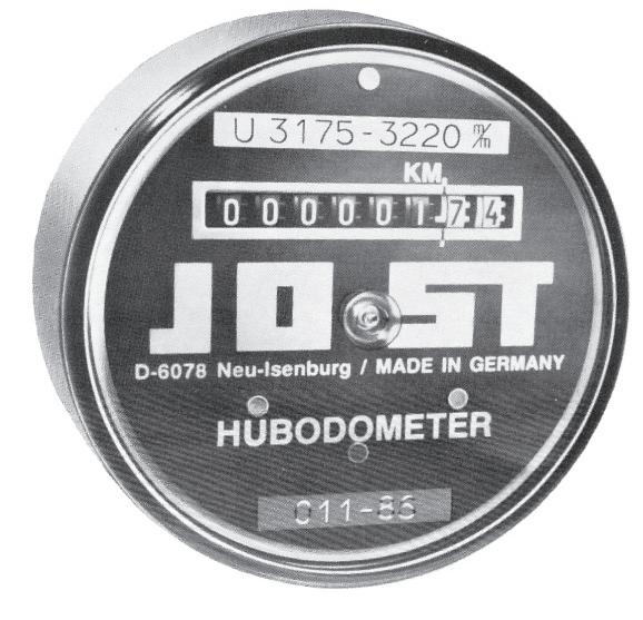
When mounting the hubodometer to your existing hub-cap proceed as follows:
Check whether there is enough clearance to the end of the axle, at least 6 mm clearance is required after mounting. The contact surface of the hub-cap must be flat, if necessary by machining. Drill the concentric 13 mm mounting hole. Install the hubodometer with the spring washer and nut supplied.
Torque the nut to 15Nm (1,5mkp) maximum, just sufficient to flatten the spring washer.
Hubodometer - short version
Where fitting has to take place in a restricted space this type of Hubodometer is used. It has a shortened clamping bolt. Fitting is effected using a special plain nut and a combined sealing/retaining ring. Tightening torque max. 15 Nm (1,5 mkp).
Fixing and centring in the axle cap requires a concentric hole of 15,1 mm diameter. With axle caps of more than 2 mm wall thickness the nut should be counterbored.
The Hubodometer must be fitted concentrically. Oscillations due to running out of true will impair life and accuracy. Check that the permissible vehicle width is not exceeded when the Hubodometer is fitted. No chemical agents should be used when cleaning the Hubodometer.
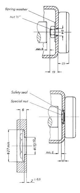


JOST Pre mi um Forged Al loy Whee ls are ma nu factured to exact ing st andards to su i t Aust ralian c ond i tion s.
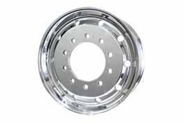
r and Superchrome™ finishes
JW
JOST WHEEL SUPECHROME 9.00 X 22.5 285 PCD 106 INSET 10 STUD
JW 90028526P OE JOST WHEEL POLISHED 9.00 x 22.5 285 PCD 26 BOLT 10 STUD
JW 90028526SC JOST WHEEL SUPERCHROME 9.00 x 22.5 285 PCD 26 BOLT 10 STUD 22.5x9.0152.21028526220.14125KG28.6
JW 90028526SC SteerJOST WHEEL SUPERCHROME STEER 9.00 x 22.5 285 PCD 26 BOLT 10 STUD22.5x9.0152.21028526220.14125KG28.6
JW
JW 90033532M OE JOST WHEEL MACHINED 9.00 X 22.5
JW SLEEVE SINGLE 32MMSLEEVE NUT M22 X 1.5 MM 32MM HEX CAST STEEL STEER
JW SLEEVE TWIN 32MMSLEEVE NUT M22 X 1.5 MM 32MM HEX CAST STEEL DRIVE USE
JW LUG NUT 32 MMLUG NUT FOR WHEELS M22 X 1.5 32 MM HEX CAST STEEL.
JW LUG NUT 33 MMLUG NUT FOR WHEELS M22 X 1.5 33 MM HEX CAST STEEL.
JW LUG NUT COVER 33 MMLUG NUT COVER 33 MM STEEL AND CHROME.
JW NUT COVER 33MM33MM LUG NUT COVERS
JW RIM GAUGE JOST RIM GAUGE FLANGE WEAR INDICATOR
JW SCANIA SLEEVE SINGLESLEEVE NUT 33MM HEX 7/8 X 11 BSF THREAD STEER USE
JW SCANIA SLEEVE TWINSLEEVE NUT 33MM HEX 7/8 X 11 BSF THREAD DRIVE USE
Refer to the JOST website www.jostaustralia.com.au for the full wheel catalogue.
Refer to the JOST website www.jostaustralia.com.au for the full wheel catalogue.
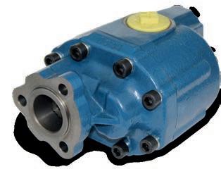
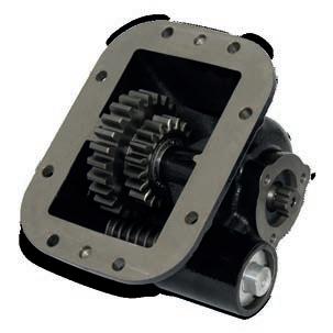
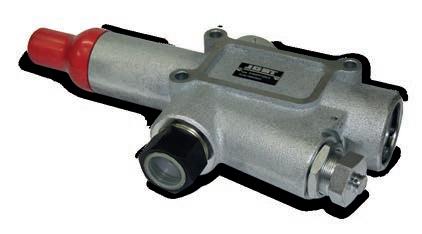
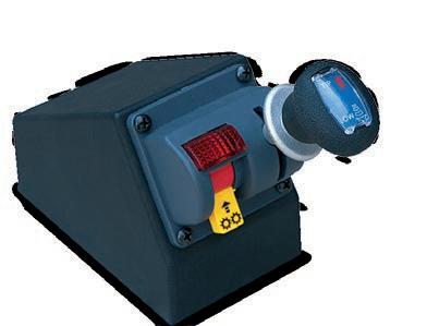
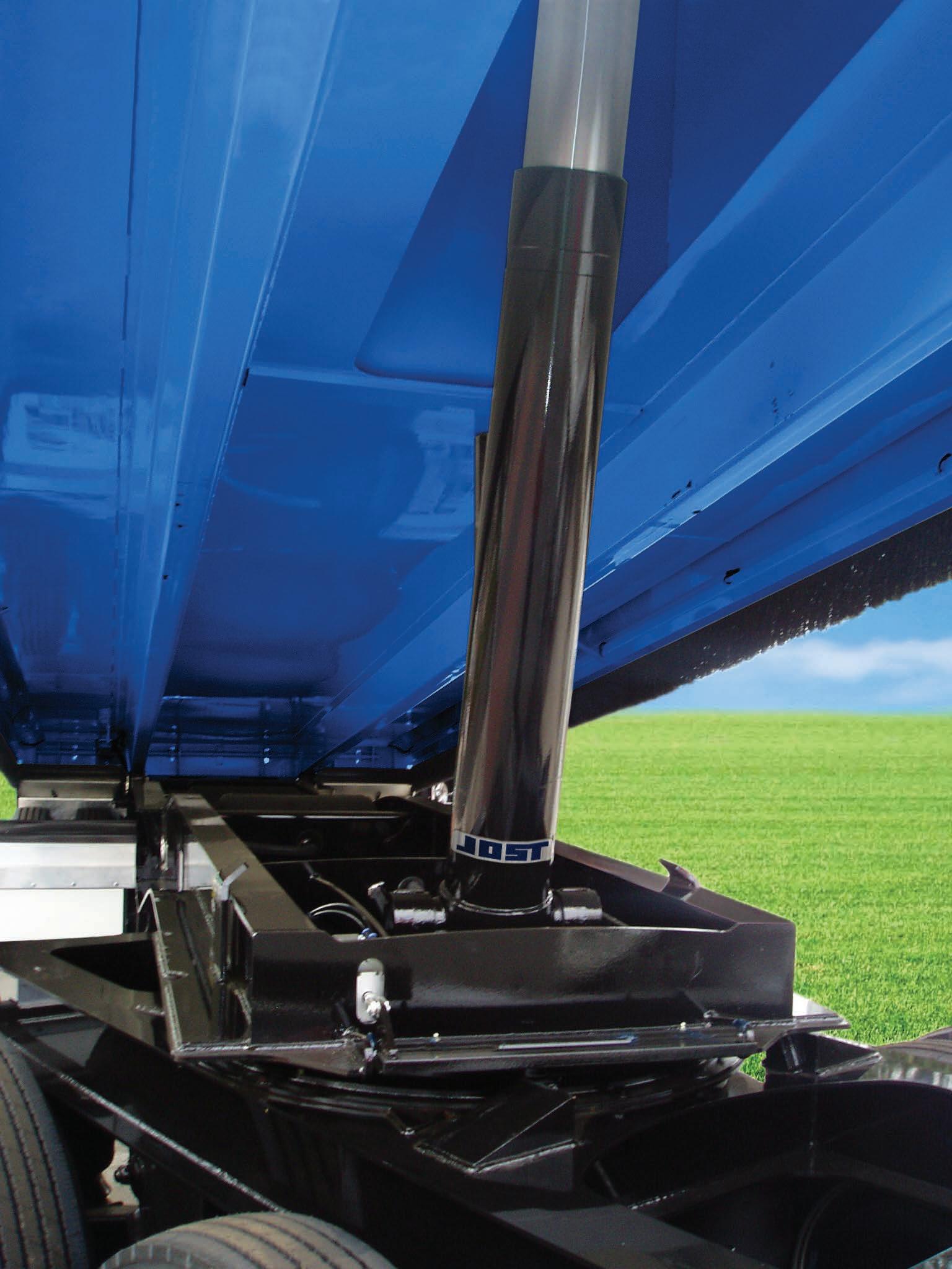
•All stage hard chroming
•Large stage overlap creating market leading strength & stability
•Heavy Duty Forged double welded Trunnion
•Spherical seal and bearing design
•Full lifting capacity at industry standard 135bar operating pressure
•Full 2 year warranty backed by JOST Australia nationwide support
Refer to the JOST website www.jostaustralia.com.au for the full Hydraulic catalogue.
Tools To Make Your Job Easier
•Jost Australia offer a selection of tools and gauges to make your job easier.
•Including simple ‘No-Go’ gauges in addition to rated lifting tools and fifth wheel testers.
•All tools are designed for common ADR specified wear limits as well as JOST specific tolerances.
•Tools to suit king pins, locking jaws, coupling pins, tow eye bushes, ball couplings and more.
Fig.Description
Part No.
1 Lock jaw gauge to suit 36, 37, 42JOSTGAUGELOCKJAW
2 Skid plate gauge to suit 50mm king pinJOSTGAUGESKIDPLATE50MM
2a Skid plate gauge to suit 90mm king pinJOSTGAUGESKIDPLATE90MM
3 Tow eye gauge
4 King pin Gauge
5 RO500 gauge
JOSTGAUGEGNIM150
JOSTGAUGEKINGPIN
JOSTGAUGERO500
6 50mm king pin lock tester SK7600000
6a 90mm king pin lock tester SK7600090