Ford Fiesta
Service

Ford Fiesta
Service
Air cleaner element renewal . . . . . . . . . . . . . . . . . . . . . . . . . . . . . . . .31
Air cleaner temperature control check . . . . . . . . . . . . . . . . . . . . . . . .29
Auxiliary drivebelt check . . . . . . . . . . . . . . . . . . . . . . . . . . . . . . . . . . .20
Battery electrolyte level check . . . . . . . . . . . . . . .see “Weekly checks”
Battery terminal check . . . . . . . . . . . . . . . . . . . . . . . . . . . . . . . . . . . .17
Brake hydraulic fluid renewal . . . . . . . . . . . . . . . . . . . . . . . . . . . . . . .33
Brake hydraulic system seal and hose renewal . . . . . . . . . . . . . . . . .32
Brake pipe and hose check . . . . . . . . . . . . . . . . . . . . . . . . . . . . . . . .26
Choke adjustment check . . . . . . . . . . . . . . . . . . . . . . . . . . . . . . . . . . .9
Contact breaker point renewal and distributor lubrication - OHV engines . . . . . . . . . . . . . . . . . . . . . . . . . . . . . . . . . . . . . . . . .23
Crankcase ventilation system check . . . . . . . . . . . . . . . . . . . . . . . . .28
Emission control filter element renewal - CVH engines . . . . . . . . . . .30
Engine coolant renewal . . . . . . . . . . . . . . . . . . . . . . . . . . . . . . . . . . .36
Engine idle speed check . . . . . . . . . . . . . . . . . . . . . . . . . . . . . . . . . . .10
Engine oil and filter renewal . . . . . . . . . . . . . . . . . . . . . . . . . . . . . . . . .3
Engine valve clearance check - OHV engines . . . . . . . . . . . . . . . . . .18
Exhaust system check . . . . . . . . . . . . . . . . . . . . . . . . . . . . . . . . . . . . .7
Fluid leak check . . . . . . . . . . . . . . . . . . . . . . . . . . . . . . . . . . . . . . . . . .5
Fluid level checks . . . . . . . . . . . . . . . . . . . . . . . . .see “Weekly checks”
Front and rear brake pad/shoe check . . . . . . . . . . . . . . . . . . . . . . . . .4
Degrees of difficulty
Easy, suitable for novice with little experience
Capacities
With filter:
Front wheel alignment check . . . . . . . . . . . . . . . . . . . . . . . . . . . . . . .35
Gearbox oil level check . . . . . . . . . . . . . . . . . . . . . . . . . . . . . . . . . . .22
Handbrake check . . . . . . . . . . . . . . . . . . . . . . . . . . . . . . . . . . . . . . . .19
Hinge and lock check and lubrication . . . . . . . . . . . . . . . . . . . . . . . .14 HT lead, distributor cap and ignition circuit check . . . . . . . . . . . . . . .13
Ignition timing and contact breaker gap (dwell angle) check - OHV engines . . . . . . . . . . . . . . . . . . . . . . . . . . . . . . . . . . . . . . . .15
Intensive maintenance . . . . . . . . . . . . . . . . . . . . . . . . . . . . . . . . . . . . .2
Introduction . . . . . . . . . . . . . . . . . . . . . . . . . . . . . . . . . . . . . . . . . . . . .1
Mixture adjustment check . . . . . . . . . . . . . . . . . . . . . . . . . . . . . . . . .11
Road test . . . . . . . . . . . . . . . . . . . . . . . . . . . . . . . . . . . . . . . . . . . . . .27
Roadwheel security check . . . . . . . . . . . . . . . . . . . . . . . . . . . . . . . . . .8
Seat belt check . . . . . . . . . . . . . . . . . . . . . . . . . . . . . . . . . . . . . . . . . . .6
Spark plug check . . . . . . . . . . . . . . . . . . . . . . . . . . . . . . . . . . . . . . . .12
Spark plug renewal . . . . . . . . . . . . . . . . . . . . . . . . . . . . . . . . . . . . . . .21
Steering and suspension security check . . . . . . . . . . . . . . . . . . . . . .24
Throttle damper operation check . . . . . . . . . . . . . . . . . . . . . . . . . . . .16
Timing belt renewal - CVH engines . . . . . . . . . . . . . . . . . . . . . . . . . .34
Tyre checks . . . . . . . . . . . . . . . . . . . . . . . . . . . . . .see “Weekly checks”
Underbody inspection . . . . . . . . . . . . . . . . . . . . . . . . . . . . . . . . . . . .25
Wiper blade check . . . . . . . . . . . . . . . . . . . . . . . .see “Weekly checks”
Fairly easy, suitable for beginner with some experience
and fluids
Fairly difficult, suitable for competent DIY mechanic
1.0 and 1.1 OHV . . . . . . . . . . . . . . . . . . . . . . . . . . . . . . . . . . . . . . . . .3.25 litres (5.7 Imp pints)
1.3,1.4 and 1.6 CVH . . . . . . . . . . . . . . . . . . . . . . . . . . . . . . . . . . . . . .3.50 litres (6.2 Imp pints)
Without filter:
1.0 and 1.1 OHV . . . . . . . . . . . . . . . . . . . . . . . . . . . . . . . . . . . . . . . . .2.75 litres (4.8 Imp pints)
1.3, 1.4 and 1.6 CVH . . . . . . . . . . . . . . . . . . . . . . . . . . . . . . . . . . . . . .3.25 litres (5.7 Imp pints)
Cooling system (including heater)
1.0 and 1.1 OHV . . . . . . . . . . . . . . . . . . . . . . . . . . . . . . . . . . . . . . . . . . .5.5 litres (9.7 Imp pints)
1.3 and 1.4 CVH . . . . . . . . . . . . . . . . . . . . . . . . . . . . . . . . . . . . . . . . . . .6.3 litres (11.1 Imp pints)
1.6 CVH . . . . . . . . . . . . . . . . . . . . . . . . . . . . . . . . . . . . . . . . . . . . . . . . .8.0 litres (14.1 Imp pints)
Fuel tank
All models - pre 1985, except XR2 . . . . . . . . . . . . . . . . . . . . . . . . . . . . .34 litres (7.5 gallons)
XR2 . . . . . . . . . . . . . . . . . . . . . . . . . . . . . . . . . . . . . . . . . . . . . . . . . . . . .38 litres (8.4 gallons)
All models - 1985 on . . . . . . . . . . . . . . . . . . . . . . . . . . . . . . . . . . . . . . . .40 litres (8.8 gallons)
Gearbox
4-speed . . . . . . . . . . . . . . . . . . . . . . . . . . . . . . . . . . . . . . . . . . . . . . . . . .2.8 litres (4.9 Imp pints)
Very difficult, suitable for expert DIY or professional
Oil filter type . . . . . . . . . . . . . . . . . . . . . . . . . . . . . . . . . . . . . . . . . . . . . .
Champion C104
Valve clearances (only OHV applicable): Inlet: At operating temperature 0.22 mm (0.009 in) Cold 0.20 to 0.25 mm (0.008 to 0.010 in) Exhaust: At operating temperature 0.59 mm (0.023 in) Cold 0.56 to 0.61 mm (0.022 to 0.024 in)
Drivebelt tension 4.0 mm (0.16 in) total deflection at the midpoint of the belt’s longest run
Air filter element type: 1.0 and 1.1 (OHV) Champion W153 1.3 (CVH) . . . . . . . . . . . . . . . . . . . . . . . . . . . . . . . . . . . . . . . . . . . . . . .
Champion W127 1.4 (CVH) . . . . . . . . . . . . . . . . . . . . . . . . . . . . . . . . . . . . . . . . . . . . . . .
Champion W179 1.6 (CVH) Champion W201
Spark plugs: Make and type: Mechanical system Champion RS9YCC or RS9YC Electronic system Champion RC7YCC or RC7YC Electrode gap: RS9YCC and RC7YCC 0.80 mm (0.032 in) RS9YC and RC7YC 0.75 mm (0.030 in)
Note: The spark plug gap quoted is that recommended by Champion for their specified plugs listed above. If spark plugs of any other type are to be fitted, refer to their manufacturer’s recommendations.
Contact breaker points gap 0.40 to 0.50 mm (0.016 to 0.020 in)
Dwell (mechanical ignition): Angle 48° to 52° Variation (from idle to 2000 rpm) 4° maximum Overlap (lobe-to-lobe variation) 3° maximum
Timing (initial):
1.0 litre OHV (pre 1986) . . . . . . . . . . . . . . . . . . . . . . . . . . . . . . . . . . . . 12° BTDC 1.1 litre OHV (pre 1986) 6° BTDC
Ignition HT lead set: Resistance 30 k ohms maximum per lead Type: Mechanical system Champion CLS 8 boxed set Electronic system Champion CLS 9 boxed set
Brakes
Front brake pad friction material minimum thickness 1.5 mm (0.059 in) Rear brake shoe friction material minimum thickness 1.0 mm (0.04 in)
Tyre sizes: Note: Manufacturers often modify tyre sizes and pressure recommendations. The following is intended as a guide only. Refer to your vehicle handbook or a Ford dealer for the latest recommendations.
XR2 185/60 HR 13 Other models 135 SR 13, 155/70 SR 13 or 165/65 SR 13
Tyre pressures: See end of “Weekly checks”
Torque wrench settings
Nm lbf ft
Engine oil drain plug 25 18
Radiator coolant drain plug 1.5 1.1 Gearbox oil filler/level plug 27 20 Roadwheel bolts . . . . . . . . . . . . . . . . . . . . . . . . . . . . . . . . . . . . . . . . . . 100 74
Spark plugs: OHV engines 13 to 20 10 to 15 CVH engines 27 20 Brake caliper piston housing bolts 23 17
The maintenance intervals in this manual are provided with the assumption that you will be carrying out the work yourself. These are the minimum maintenance intervals recommended by the manufacturer for vehicles driven daily. If you wish to keep your vehicle in peak condition at all times, you may
wish to perform some of these procedures more often. We encourage frequent maintenance, because it enhances the efficiency, performance and resale value of your vehicle.
If the vehicle is driven in dusty areas, used to tow a trailer, or driven frequently at slow
speeds (idling in traffic) or on short journeys, more frequent maintenance intervals are recommended.
When the vehicle is new, it should be serviced by a factory-authorised dealer service department, in order to preserve the factory warranty.
Every 250 miles (400 km) or weekly
Refer to “Weekly checks”
Every 6000 miles (10 000 km) or 6 months - whichever comes sooner
Renew engine oil and filter (Section 3)
Check brake pads or shoes for wear (front and rear) (Section 4)
Check operation of brake fluid level warning indicator (Section 4)
Inspect engine bay and underside of vehicle for fluid leaks or other signs of damage (Section 5)
Check function and condition of seat belts (Section 6)
Check condition and security of exhaust system (Section 7)
Check tightness of wheel nuts (Section 8)
Check choke adjustment (Section 9)
Check idle speed (Section 10)
Check mixture adjustment (Section 11)
Check spark plugs (Section 12)
Check HT leads, distributor cap and ignition circuit (Section 13)
Check operation of latches, check straps and locks; lubricate if necessary (Section 14)
Check ignition timing and contact breaker gap (dwell angle) (OHV engines) (Section 15)
Check operation of throttle damper (where applicable) (Section 16)
Every 12 000 miles (20 000 km) or 12 months - whichever comes sooner
Check tightness of battery terminals, clean and neutralise corrosion (Section 17)
Check engine valve clearances - OHV engines (Section 18)
Check handbrake mechanism (Section 19)
Check condition and tension of auxiliary drivebelt (Section 20)
Every 12 000 miles (20 000 km) or 12 months - whichever comes sooner
Renew spark plugs (Section 21)
Check gearbox oil level (Section 22)
Renew distributor contact breaker points and lubricate distributor - OHV engines (Section 23)
Check security and condition of steering and suspension components, gaiters and boots (Section 24)
Inspect underbody and panels for corrosion or other damage (Section 25)
Inspect brake pipes and hoses (Section 26) Road test (Section 27) Check crankcase ventilation system (Section 28)
Every 24 000 miles (40 000 km) or 2 years - whichever comes sooner
Check air cleaner temperature control (Section 29) Renew emission control filter element - CVH engines (Section 30)
Renew air cleaner element (Section 31)
Every 36 000 miles (60 000 km) or 3 years - whichever comes sooner
Renew brake hydraulic system seals and hoses if necessary (Section 32)
Renew brake hydraulic fluid (Section 33)
Renew timing belt - CVH engines (Section 34) Check front wheel alignment (Section 35)
Every 2 years, regardless of mileage
Renew coolant (Section 36)
Engine compartment - OHV 1 Coolant expansion tank

Engine oil dipstick
Oil filter
Ignition coil
Brake fluid reservoir
Battery
Cooling fan
Oil filler cap
Carburettor (air cleaner removed)
Alternator
Washer reservoir
Engine compartment - CVH 1 Coolant expansion tank
Engine oil dipstick
Carburettor (air cleaner removed)

Fuel pump
Distributor
Ignition coil
Windscreen wiper motor
Ignition amplifier module
Battery
Brake fluid reservoir
Cooling fan
Oil filler cap
Washer reservoir


This Chapter is designed to help the home mechanic maintain his/her vehicle for safety, economy, long life and peak performance.
The Chapter contains a master maintenance schedule, followed by Sections dealing specifically with each task in the schedule. Visual checks, adjustments, component renewal and other helpful items are included. Refer to the accompanying illustrations of the engine compartment and the underside of the vehicle for the locations of the various components.
Servicing your vehicle in accordance with the mileage/time maintenance schedule and the following Sections will provide a planned maintenance programme, which should result in a long and reliable service life. This is a comprehensive plan, so maintaining some items but not others at the specified service intervals, will not produce the same results.
As you service your vehicle, you will discover that many of the procedures canand should - be grouped together, because of the particular procedure being performed, or because of the close proximity of two otherwise-unrelated components to one another. For example, if the vehicle is raised for any reason, the exhaust can be inspected at the same time as the suspension and steering components.
The first step in this maintenance programme is to prepare yourself before the actual work begins. Read through all the Sections relevant to the work to be carried out, then make a list and gather together all the parts and tools required. If a problem is encountered, seek advice from a parts specialist, or a dealer service department.
If, from the time the vehicle is new, the routine maintenance schedule is followed closely, and frequent checks are made of fluid levels and high-wear items, as suggested throughout this manual, the engine will be kept in relatively good running condition, and the need for additional work will be minimised.
It is possible that there will be times when the engine is running poorly due to the lack of regular maintenance. This is even more likely if a used vehicle, which has not received regular and frequent maintenance checks, is purchased. In such cases, additional work may need to be carried out, outside of the regular maintenance intervals.
If engine wear is suspected, a compression test will provide valuable information regarding the overall performance of the main internal components. Such a test can be used as a basis to decide on the extent of the work to be carried out. If, for example, a compression test indicates serious internal
engine wear, conventional maintenance as described in this Chapter will not greatly improve the performance of the engine, and may prove a waste of time and money, unless extensive overhaul work is carried out first.
The following series of operations are those most often required to improve the performance of a generally poor-running engine:
a) Clean, inspect and test the battery
b) Check all the engine-related fluids
c) Check the condition and tension of the auxiliary drivebelt
d) Renew the spark plugs
e) Inspect the distributor cap and HT leadsas applicable
f) Check the condition of the air cleaner filter element, and renew if necessary
g) Renew the fuel filter (if fitted)
h) Check the condition of all hoses, and check for fluid leaks
i) Check the idle speed and mixture settings - as applicable
If the above operations do not prove fully effective, carry out the following secondary operations:
a) Check the charging system
b) Check the ignition system
c) Check the fuel system
d) Renew the distributor cap and rotor armas applicable
e) Renew the ignition HT leads - as applicable
1 Frequent oil and filter changes are the most important preventative maintenance procedures which can be undertaken by the DIY owner. As engine oil ages, it becomes diluted and contaminated, which leads to premature engine wear.
2 Before starting this procedure, gather together all the necessary tools and materials. Also make sure that you have plenty of clean rags and newspapers handy, to mop up any spills. Ideally, the engine oil should be warm, as it will drain better, and more built-up sludge will be removed with it. Take care, however, not to touch the exhaust or any other hot parts of the engine when working under the vehicle. To avoid any possibility of scalding, and to protect yourself from possible skin irritants and other harmful contaminants in used engine oils, it is advisable to wear gloves when carrying out this work. Access to the underside of the vehicle will be greatly improved if it can be raised on a lift, driven onto ramps, or jacked
1up and supported on axle stands (see “Jacking and vehicle support” ). Whichever method is chosen, make sure that the vehicle remains level, or if it is at an angle, so that the drain plug is at the lowest point.
3 Slacken the drain plug about half a turn (see illustration) . Position the draining container under the drain plug, then remove the plug completely. If possible, try to keep the plug pressed into the sump while unscrewing it by hand the last couple of turns. Recover the sealing washer from the drain plug.
6 Move the container into position under the oil filter.
7 Using an oil filter removal tool if necessary, slacken the filter initially, then unscrew it by hand the rest of the way (see illustration) Empty the oil from the old filter into the container, and discard the filter.
8 Use a clean rag to remove all oil, dirt and sludge from the filter sealing area on the engine. Check the old filter to make sure that the rubber sealing ring hasn’t stuck to the engine. If it has, carefully remove it.
4 Allow some time for the old oil to drain, noting that it may be necessary to reposition the container as the oil flow slows to a trickle.
5 After all the oil has drained, wipe off the drain plug with a clean rag. Check the sealing washer for condition, and renew it if necessary. Clean the area around the drain plug opening, and refit the plug. Tighten the plug to the specified torque.

9 Apply a light coating of clean engine oil to the sealing ring on the new filter, then screw it into position on the engine. Tighten the filter firmly by hand only - do not use any tools. Wipe clean the filter and sump drain plug.
10 Remove the old oil and all tools from under the car, then lower the car to the ground (if applicable).
11 Remove the oil filler cap and withdraw the dipstick. Fill the engine, using the correct grade and type of oil (see “Lubricants and fluids” and “Capacities” in the Specifications).
An oil can spout or funnel may help to reduce spillage. Pour in half the specified quantity of oil first, then wait a few minutes for the oil to fall to the sump. Continue adding oil a small quantity at a time until the level is up to the lower mark on the dipstick. Finally, bring the level up to the upper mark on the dipstick. Insert the dipstick, and refit the filler cap.
12 Start the engine and run it for a few minutes; check for leaks around the oil filter seal and the sump drain plug. Note that there may be a delay of a few seconds before the oil pressure warning light goes out when the engine is first started, as the oil circulates through the engine oil galleries and the new oil filter, before the pressure builds up.
13 Switch off the engine, and wait a few minutes for the oil to settle in the sump once more. With the new oil circulated and the filter completely full, recheck the level on the dipstick, and add more oil as necessary.
14 Dispose of the used engine oil safely.
1 Firmly apply the handbrake, then jack up the front and rear of the car and support it securely on axle stands (see “Jacking and vehicle support”).
2 For a quick check, the front brake disc pads can be inspected without removing the front wheels by inserting a mirror between each caliper and roadwheel (see illustrations) . If any one pad is worn down to the minimum specified thickness, all four pads (on both front wheels) must be renewed.

3 For a comprehensive check, the brake disc pads should be removed and cleaned. The operation of the caliper can then also be checked, and the condition of the brake discs can be fully examined on both sides. Refer to Chapter 9 for further information.

4 The rear brake shoe friction material can be inspected for wear without removing the roadwheels. Working beneath the vehicle, prise the plug from the brake backplate and using an inspection lamp or torch, check that the friction material thickness is not less than the minimum given in the Specifications (see illustrations) . If any one of the shoes has worn below the specified limit, the shoes must be renewed as an axle set (4 shoes).
5 At the same interval, check the function of the brake fluid level warning light. Chock the wheels, release the handbrake and switch on the ignition. Unscrew and raise the brake fluid reservoir cap whilst an assistant observes the warning light: it should come on as the level sensor is withdrawn from the fluid. Refit the cap.
16 On completion, refit the wheels and lower the car to the ground.
1 Visually inspect the engine joint faces, gaskets and seals for any signs of water or oil leaks. Pay particular attention to the areas around the rocker cover, cylinder head, oil filter and sump joint faces. Bear in mind that over a period of time some very slight seepage from these areas is to be expected but what you are really looking for is any indication of a serious leak. Should a leak be found, renew the offending gasket or oil seal by referring to the appropriate Chapter(s) in this manual.
2 Similarly, check the transmission for oil leaks, and investigate and rectify and problems found.
3 Check the security and condition of all the engine related pipes and hoses. Ensure that all cable-ties or securing clips are in place and in good condition. Clips which are broken or missing can lead to chafing of the hoses, pipes or wiring which could cause more serious problems in the future.
4 Carefully check the condition of all coolant, fuel and brake hoses. Renew any hose which is cracked, swollen or deteriorated. Cracks will show up better if the hose is squeezed. Pay close attention to the hose clips that secure the hoses to the system components. Hose clips can pinch and puncture hoses, resulting in leaks. If wire type hose clips are used, it may be a good idea to replace them with screw-type clips.
5 With the vehicle raised, inspect the fuel tank and filler neck for punctures, cracks and


other damage. The connection between the filler neck and tank is especially critical. Sometimes a rubber filler neck or connecting hose will leak due to loose retaining clamps or deteriorated rubber.
6 Similarly, inspect all brake hoses and metal pipes. If any damage or deterioration is discovered, do not drive the vehicle until the necessary repair work has been carried out. Renew any damaged sections of hose or pipe.
7 Carefully check all rubber hoses and metal fuel lines leading away from the petrol tank. Check for loose connections, deteriorated hoses, crimped lines and other damage. Pay particular attention to the vent pipes and hoses which often loop up around the filler neck and can become blocked or crimped. Follow the lines to the front of the vehicle carefully inspecting them all the way. Renew damaged sections as necessary.
8 From within the engine compartment, check the security of all fuel hose attachments and pipe unions, and inspect the fuel hoses and vacuum hoses for kinks, chafing and deterioration.
9 Check the condition of all exposed wiring harnesses.
1 Periodically check the belts for fraying or other damage. If evident, renew the belt.
2 If the belts become dirty, wipe them with a damp cloth using a little detergent only.
3 Check the tightness of the anchor bolts and if they are ever disconnected, make quite sure that the original sequence of fitting of washers, bushes and anchor plates is retained.
With the vehicle raised on a hoist or supported on axle stands (see “Jacking and vehicle support” ), check the exhaust system for signs of leaks, corrosion or damage and check the rubber mountings for condition and security (see illustration) . Where damage or corrosion are evident, renew the system complete or in sections, as applicable, using the information given in Chapter 4.
7.1 Inspect the exhaust system rubber mounting
On models equipped with carburettors of Ford manufacture, refer to Chapter 4, Section 9 and check that the choke is adjusted within the stated parameters.
1Note: Refer to the precautions given in Section 1 of Chapter 4 before proceeding.
Note: Before carrying out any carburettor adjustments, ensure that the ignition timing and spark plug gaps are set as specified. To carry out this adjustment, an accurate tachometer will be required.
1 Ensure that the air cleaner is correctly fitted, and that all vacuum hoses and pipes are securely connected and free from restrictions, then run the engine until it is at normal operating temperature.
2 With the engine at normal operating temperature, adjust the idle speed screw (see illustration) to obtain the specified idle speed, using a tachometer to ensure accuracy.

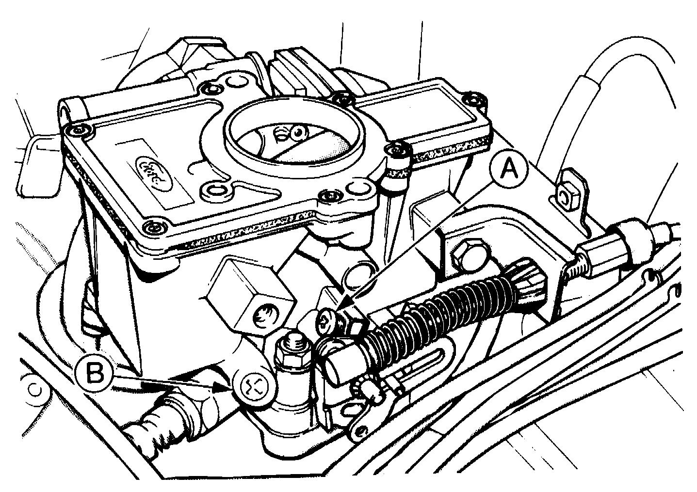
10.2 Ford 1V carburettor idle speed screw (A) and mixture screw (B)
3 This procedure must be carried out with the radiator cooling fan in operation. To keep the fan running during the adjustment procedure, disconnect the wiring multi - plug from the thermal switch (located in the thermostat housing) and bridge the two contacts in the plug with a short length of wire (see illustration). Disconnect the wire and refit the multi-plug on completion of the adjustments. Make sure that the engine and ignition are switched off when connecting and disconnecting the bridging wire.

4 Ensure that the air cleaner is correctly fitted, and that all vacuum hoses and pipes are securely connected and free from restrictions, then run the engine until it is at normal operating temperature.
5 With the engine at normal operating temperature, connect a tachometer in accordance with the manufacturer’s instructions.
6 Start the engine, run it at 3000 rpm for 30 seconds and then let it idle. Turn the idle speed adjusting screw in or out as necessary to bring the speed to that given in the Specifications (see illustration)

With the wheels on the ground, slacken each wheel bolt by a quarter turn, then retighten it immediately to the specified torque.
10.3 Temporary bridging wire in cooling fan thermal switch multi-plug
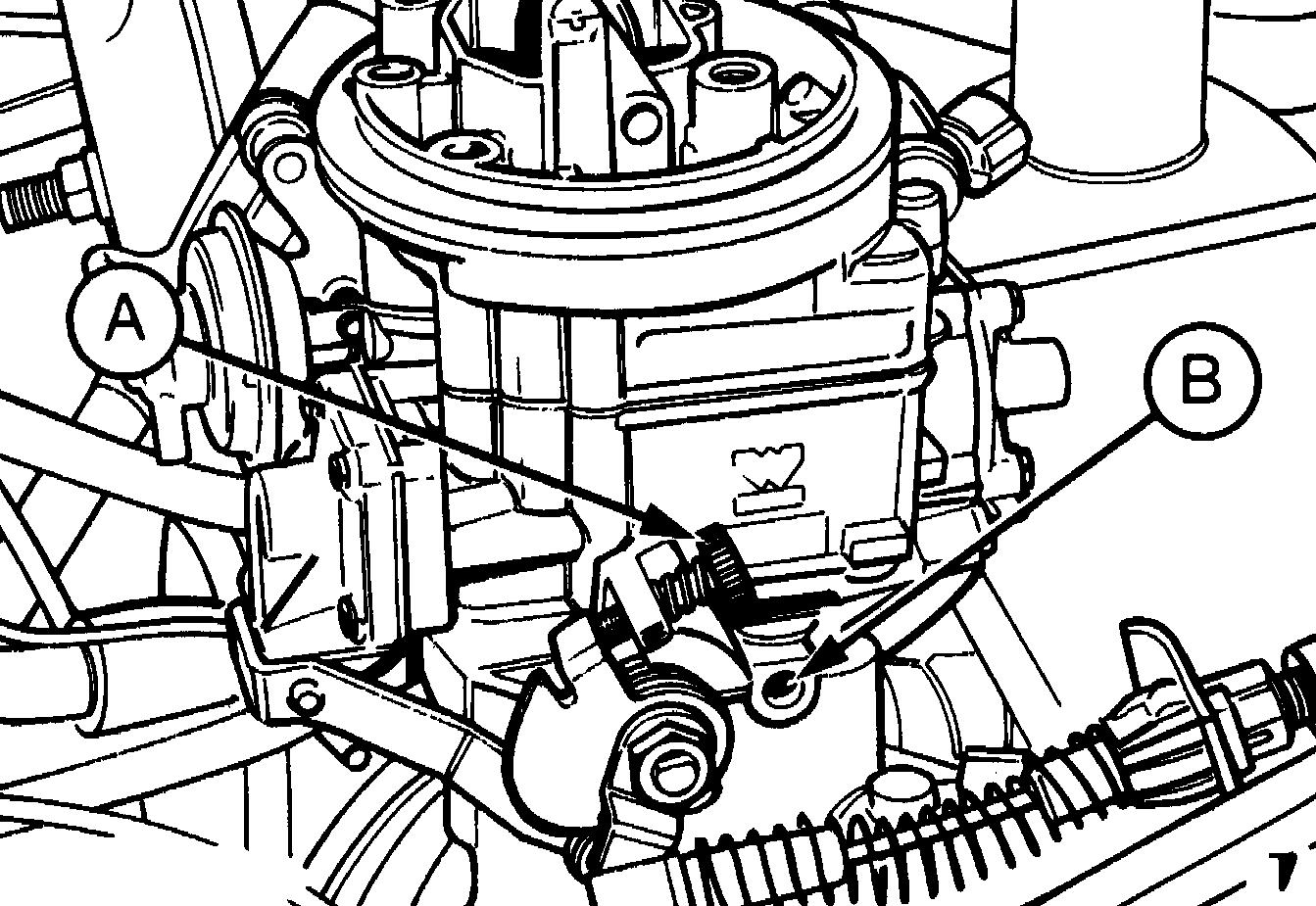
10.6 Ford VV carburettor idle speed screw (A) and mixture screw (B)
Weber 2V carburettor
7 Refer to the information relating to the Ford 1V carburettor for details, and to the accompanying illustration (see illustration) for the adjusting screws. Ensure that the engine fan is operating by pulling the two wires from the sensor, and connecting the wires with a jumper lead.


Weber 2V DFTM
8 Before carrying out this adjustment, ensure that the air cleaner is correctly fitted and that all vacuum hoses and pipes are securely connected and free from restrictions. Run the engine until it is at normal operating temperature.
9 The cooling fan must be kept running during the adjustment procedure. To do this, disconnect the wiring multi - plug from the thermal switch (located in the thermostat housing) and bridge the two contacts in the plug with a short length of wire.
10 Start the engine and turn the idle speed adjustment screw (see illustration) to obtain the specified idle speed, using a tachometer to ensure accuracy.
11 Refer to the information relating to the Weber 2V DFTM carburettor for details, and to the accompanying illustration (see illustration) for the adjusting screws.
12 Before carrying out this adjustment, ensure that the air cleaner is correctly fitted and that all vacuum hoses and pipes are securely connected and free from restrictions. Run the engine until it is at normal operating temperature.
13 Connect a reliable tachometer to the engine in accordance with the manufacturer’s instructions.
14 Increase the engine speed to 3000 rpm and hold it at this speed for 30 seconds, then allow the engine to idle. Adjust the idle speed to within the specified range by turning the idle speed screw (see illustration)
Note: Refer to the precautions given in Section 1 of Chapter 4 before proceeding.
Note: Before carrying out any carburettor adjustments, ensure that the ignition timing and spark plug gaps are set as specified. To carry out the adjustments an accurate tachometer and an exhaust gas analyser (CO meter) will be required. Adjustment of the idle mixture setting should not be attempted in territories where this may cause a violation of exhaust emission regulations. Where these regulations are less stringent the following procedures may be used.
1 Ensure that the air cleaner is correctly fitted and that all vacuum hoses and pipes are securely connected and free from restrictions, then run the engine until it is at normal operating temperature.
2 Using a small screwdriver, prise out the tamperproof plug (if fitted) over the idle mixture screw.
3 Connect the CO meter and tachometer according to the manufacturer’s instructions.
4 Adjust the idle speed to the specified setting.
5 Run the engine at 3000 rpm for 30 seconds to clear the inlet manifold of excess fuel. Repeat this operation every 30 seconds during the adjustment procedure.
6 Turn the idle mixture screw in the desired direction to achieve the fastest possible engine speed consistent with smooth, even running or the correct specified CO reading on the meter scale.
7 If necessary, readjust the idle speed setting on completion. Fit a new tamperproof plug to the mixture screw.
8 This procedure must be carried out with the radiator cooling fan in operation. To keep the fan running during the adjustment procedure, disconnect the wiring multi - plug from the thermal switch (located in the thermostat housing) and bridge the two contacts in the plug with a short length of wire. Disconnect the wire and refit the multi-plug on completion of the adjustments. Make sure that the engine and ignition are switched off when connecting and disconnecting the bridging wire.
9 To adjust the mixture accurately, connect a CO (exhaust gas) analyser and a tachometer in accordance with the manufacturer’s instructions.
10 Ensure that the air cleaner is correctly fitted and that all vacuum hoses and pipes are securely connected and free from restrictions, then run the engine until it is at normal operating temperature.
11 Using a thin, sharp screwdriver, prise out the tamperproof plug which covers the mixture screw.
12 Start the engine and run it at 3000 rpm for 30 seconds, then allow it to return to idle. Turn the mixture screw in (weak) or out (rich) until the CO level is within the specified range as indicated on the analysing equipment. The adjustment must be carried out within 30 seconds; otherwise, again increase the engine speed for 30 seconds before continuing with the adjustment.
13 Once the mixture is correct, adjust the idle speed then recheck the mixture.
14 Switch off the engine and remove the tachometer and the exhaust gas analyser. Fit a new tamperproof plug to the mixture screw.
15 In the absence of a suitable exhaust gas analyser, an approximate setting of the mixture screw may be made by turning the screw inwards (engine idling) until the idle speed just begins to drop. Unscrew the screw
the smallest amount necessary to achieve smooth idle. The CO level of the exhaust gas should be checked by your dealer at the earliest opportunity and further adjustment carried out as may be necessary.
16 Refer to the information relating to the Ford 1V carburettor for details. Ensure that the engine fan is operating by pulling the two wires from the sensor, and connecting the wires with a jumper lead.

17 The cooling fan must be kept running during the adjustment procedure. To do this, disconnect the wiring multi - plug from the thermal switch (located in the thermostat housing) and bridge the two contacts in the plug with a short length of wire.
18 Ensure that the air cleaner is correctly fitted and that all vacuum hoses and pipes are securely connected and free from restrictions, then run the engine until it is at normal operating temperature.
19 Using a small screwdriver, prise out the tamperproof plug (if fitted) over the idle mixture screw.
20 Connect the CO meter and tachometer according to the manufacturer’s instructions.
21 Adjust the idle speed to the correct setting.
22 Run the engine at 3000 rpm for 30 seconds to clear the inlet manifold of excess fuel. Repeat this operation every 30 seconds during the adjustment procedure.
23 Turn the idle mixture screw in the desired direction to achieve the fastest possible engine speed consistent with smooth, even running; or the correct specified CO reading on the meter scale.
24 If necessary, readjust the idle speed setting. Refit the cooling fan multi-plug and fit a new tamperproof plug.
25 Refer to the information relating to the Weber 2V DFTM carburettor for details.

26 Ensure that the air cleaner is correctly fitted and that all vacuum hoses and pipes are securely connected and free from restrictions, then run the engine until it is at normal operating temperature.
27 With the engine at normal operating temperature, connect a tachometer and exhaust gas analyser in accordance with the manufacturer’s instructions.
28 Prise out the tamperproof plug from the mixture screw hole in the throttle valve block.
29 Wait for the radiator cooling fan to operate, then raise the engine speed to 3000 rpm, hold it at this speed for 30 seconds, return to idle and check the exhaust CO level on the exhaust gas analyser. If it is not as specified, turn the mixture screw (clockwise to weaken) and repeat the checking procedure.
30 On completion, fit a new tamperproof plug.


1 Pull the HT lead from each plug by grasping the end connector. Clean around each spark plug (see illustration) . Remove each plug (see illustration) and check its electrode gap, which should be within the limits stated in Specifications.

2 To adjust the gap, bend the outer electrode with a proper spark plug gapping tool. Recheck the gap using feeler blades or wire gauges (see illustrations)

3 Note that the correct functioning of each plug is vital for the correct running and efficiency of the engine. It is essential that the plugs fitted are appropriate for the engine and the suitable type is specified at the beginning of this Chapter. Spark plug cleaning is rarely
necessary and should not be attempted unless specialised equipment is available as damage can easily be caused to the firing ends.
4 The appearance of a removed spark plug can give some indication of the condition or state of tune of the engine, but as modern engines run on a weaker fuel/air mixture in order to conform to current emission control regulations, a rather whiter appearance of the spark plug electrode area must be expected than was the case on older cars. As the mixture control is preset during production, a black appearance of the plug electrode will normally be due to oil passing worn piston rings or valve stem oil seals, unless the carburettor has been tampered with.
15 When installing the plugs use a long reach socket, apply a little grease to the threads of the plugs (see illustration) and tighten them only to the specified torque wrench setting. Overtightening may damage the plug or its seat.