Contributed as a team member on the design and documentation of the new terminal at John Glenn International Airport (CMH). Assisted with technical documentation and detailing on the exterior envelope scope. Championed technical documentation of the Amenity and Restroom scope through design development and construction document phases. Coordinated with consultants and delegated tasks. Assisted the development of other scopes as required. Acted as a team member with Moody Nolan Cares, the firm’s cultural and outreach group.
Perkins&Will
2019–2023
Designer I–Designer II* Washington, D.C.
Acted as a member of a team to deliver a range of projects at all phases of design. Created schematic design presentations, constructed physical models to help win new projects. Developed construction contract documents and coordinated schemes with external consultants. Adopted bridging documents and developed them into construction contract documents. Administered the design intent through construction administration. Participated in client and CCA meetings, completing punch lists, documenting existing conditions, and on-site observation and review of construction for compliance with contract documents.
* Promoted to Designer II in August of 2021.
Loysen+Kreuthmeier Architects
2014–2015
Intern Architect Pittsburgh, PA
Produced design and contract documents through all stages of design. Served as an administrator of the contract documents through construction.
Ken Linsteadt Architects
2017
Intern Architect San Francisco, CA
Designed the preliminary cladding scheme for a cantilevered superstructure.
Bohlin Cywinksi Jackson
2016
Project Designer Philadelphia, PA
Coordinated and edited contract documents for multiple storefront projects of an international specialty coffee roaster.
Renfro Design Group
2016
Lighting Designer New York, NY
Collaborated with architects to conceptualize and plan spaces with light. Constructed lighting mock-ups, technical drawings, renderings, presentations, specifications, fixture and control zone layouts, and lighting specifications that meet project constraints.
Master of Architecture
2015–2 018
University of Cincinnati Cincinnati, OH
College of Design, Architecture, Art, & Planning (DAAP)
Graduate Certificate in Business Foundations 2018
University of Cincinnati Cincinnati, OH
Carl H. Lindner College of Business
Bachelor of Science in Architecture
2009 – 2014
Kent State University Kent, OH
College of Architecture & Environmental Design (CAED)
OUTSIDE DIAMETER TIE ROD WITH ARCHITECTURAL CLEVIS FORK AT EACH END AND CENTERED TURNBUCKLE; BLACK POWDER COAT FINISH; RE. STRUCTURAL DRAWINGS
STEEL GUTTER; BLACK POWDER COAT FINISH; SLOPE TO DOWNSPOUT
CLAMP HARDWARE, TYP.
LAMINATED
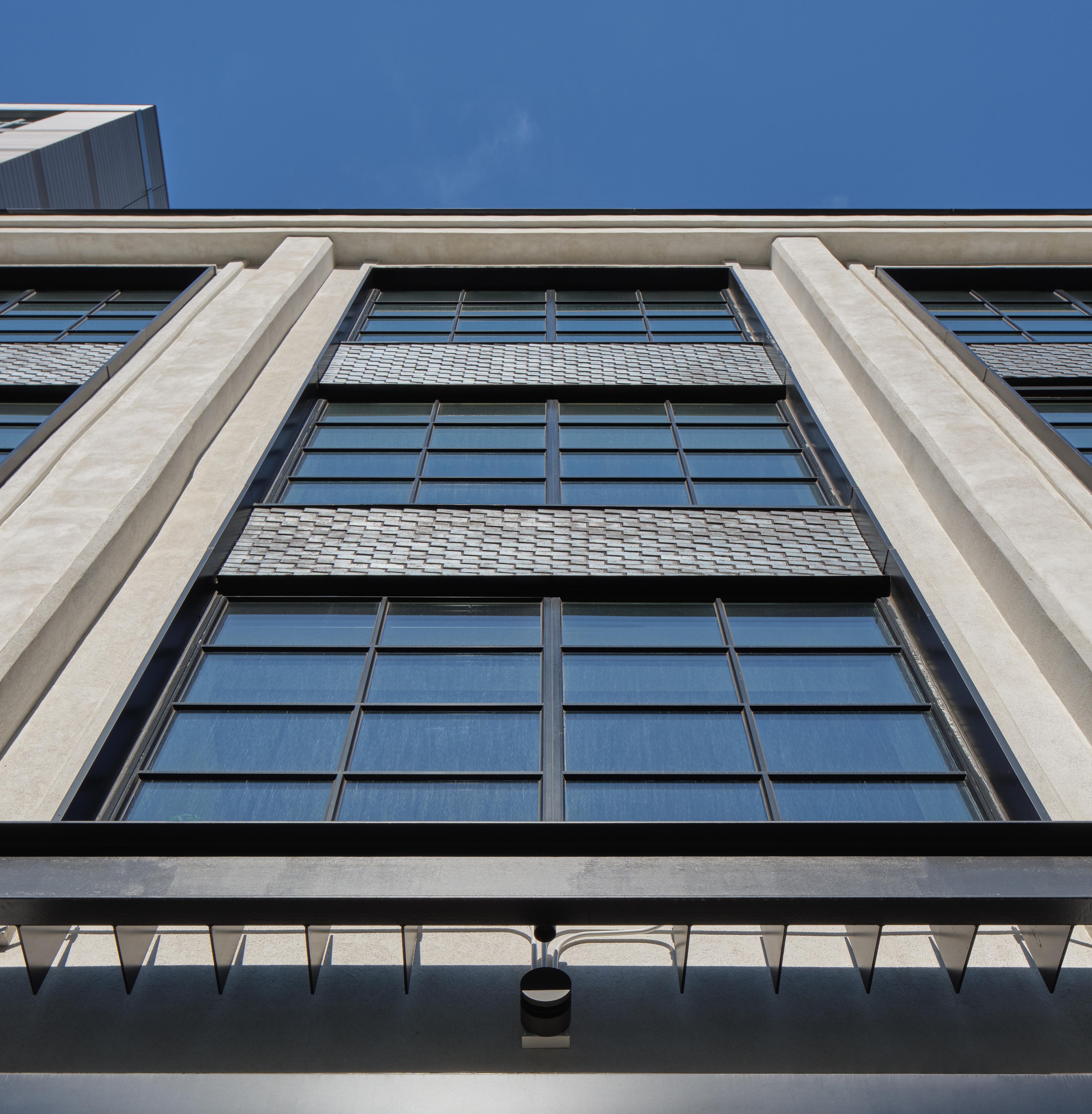
administration to be more of a “brow.” Originally, a more intensive system of internal gutters and drains channeled water so as to avoid splashing pedestrians and building visiters entering and exiting on the street below. The brow conceals uplighting fixtures on the facade.
ROOF DECK
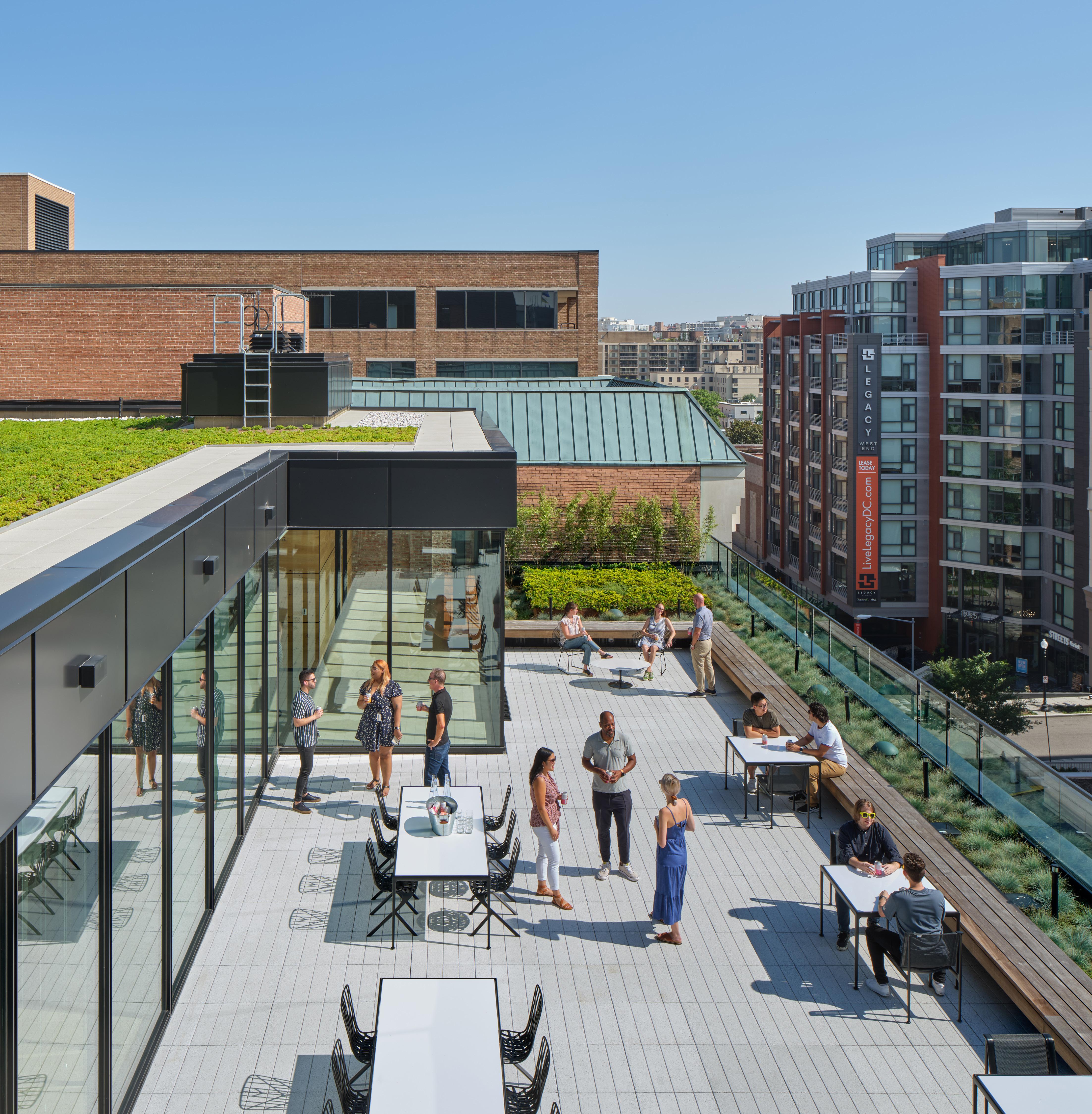
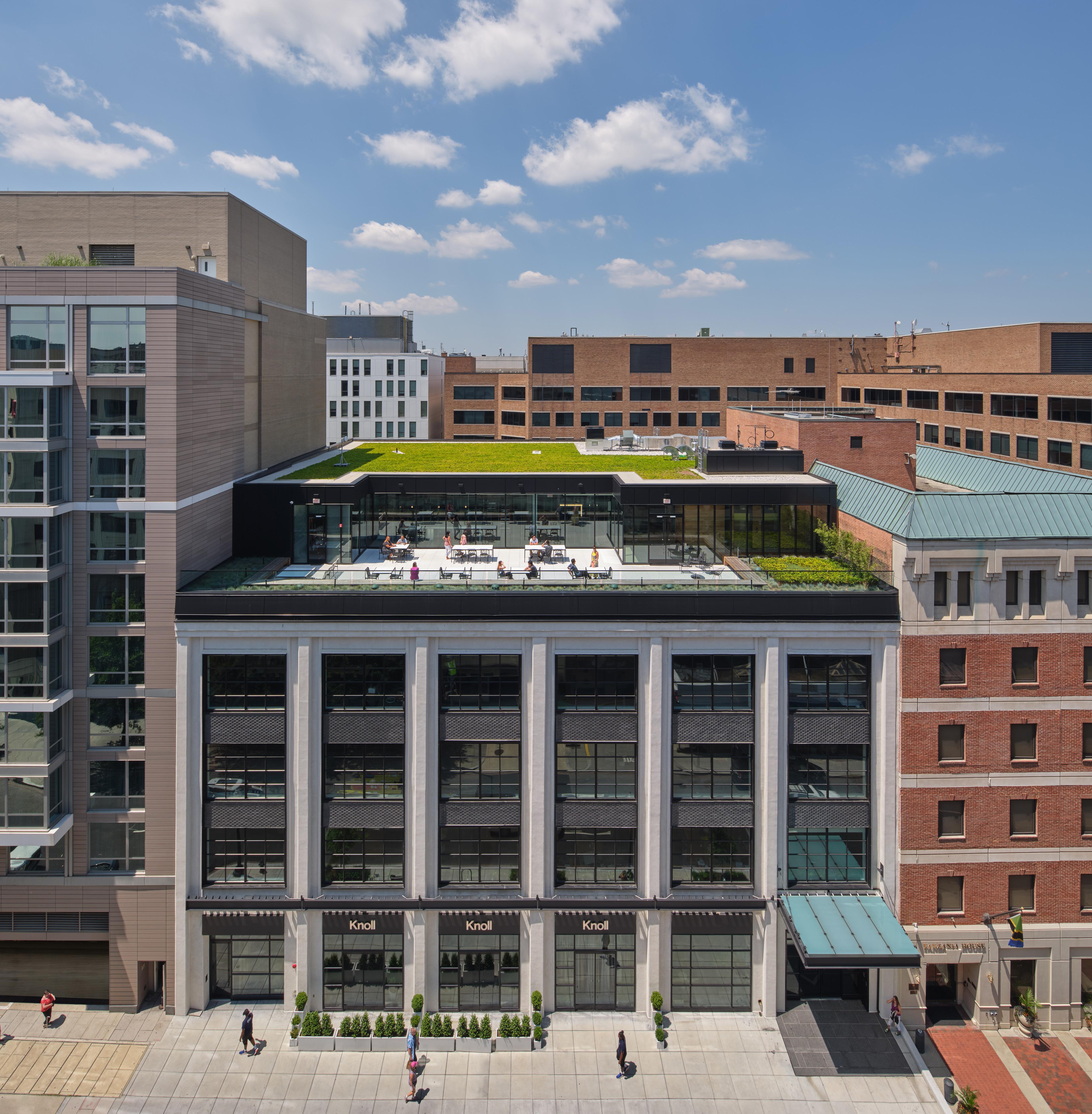
The addition of a rooftop amenity space was sought by the client. The top deck of the parking garage was formerly unoccupied and featured a series of skylights, which were removed. Coordinating with the structural engineer, the new penthouse and roof deck structure is supported on steel dunnage and features a mix of intensive and extensive green roof systems.
PLANT MATERIAL
LINEAR LED LIGHT FIXTURE; SL-2 WOOD BENCH, TYP.
PEDESTAL PAVERS, TYP.
CAST-IN-PLACE CONC. PLANTER WALL
STRUCTURAL STEEL DUNNAGE
EXISTING CONCRETE ROOF DECK
SBS MOD-BIT FLASHING;
ALUMINUM CAP RAIL; POWDER COAT FINISH
DRAIN INSPECTION HATCH
WINDOW WASHING ANCHOR
PREFINISHED ALUMINUM COPING GLASS RAILING SYSTEM
CAST-IN-PLACE CONCRETE CURB
PENTHOUSE 117' - 11 5/8"
ACM PANEL ON GALVANIZED CFMF
LINEAR LED LIGHT FIXTURE
CONT. ALUMINUM COPING W/ FORMED DRIP EDGE OVER ACM PANEL
ISOLATE ALUMINUM FROM STEEL AT INTERFACE WITH NEOPRENE PAD
STEEL BASE PLATE ON GROUT BED; RE: STRUCTURAL DRAWINGS
This project was a learning experience and served as a foundational and introductory project to the architectural design detail. As an adaptive reuse project, the major factors of the process involved verifying existing conditions, working within constrains and within a historical context.
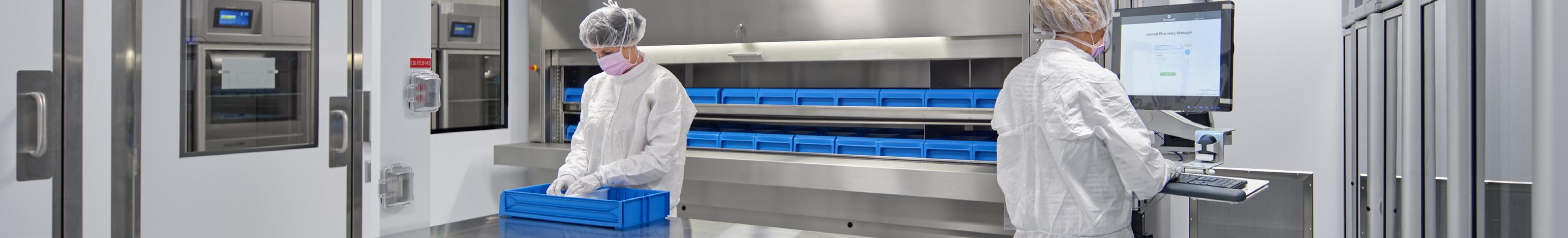
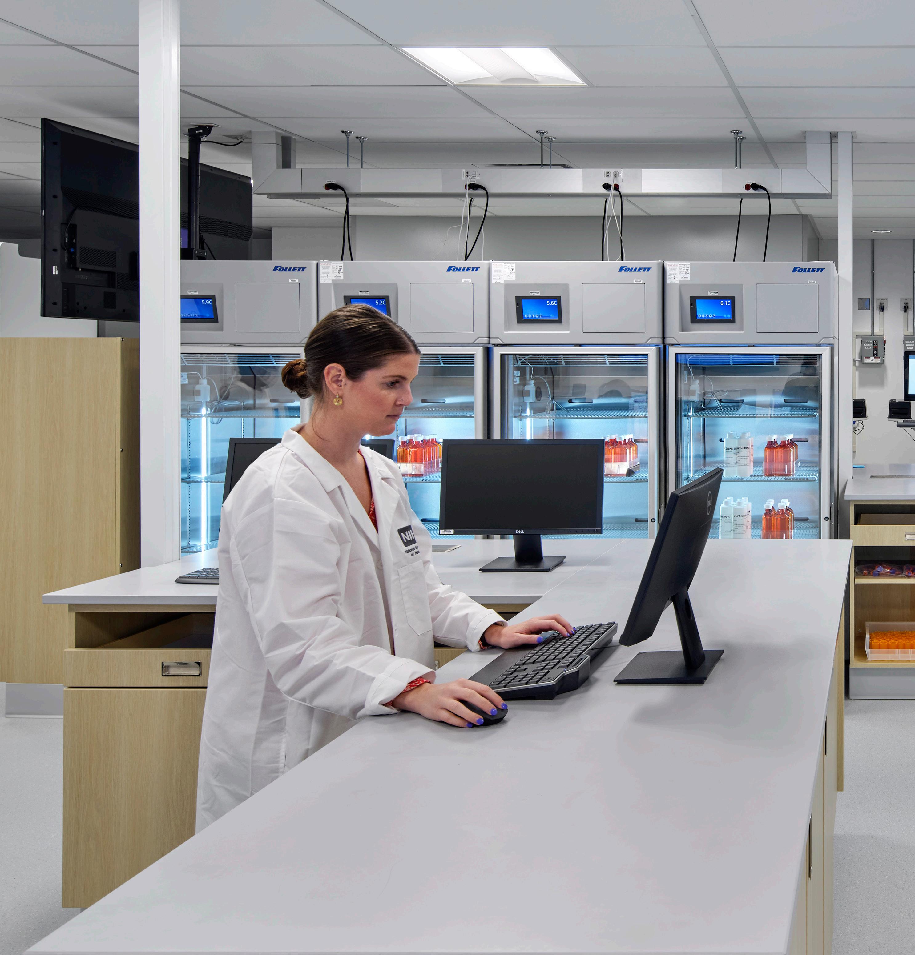
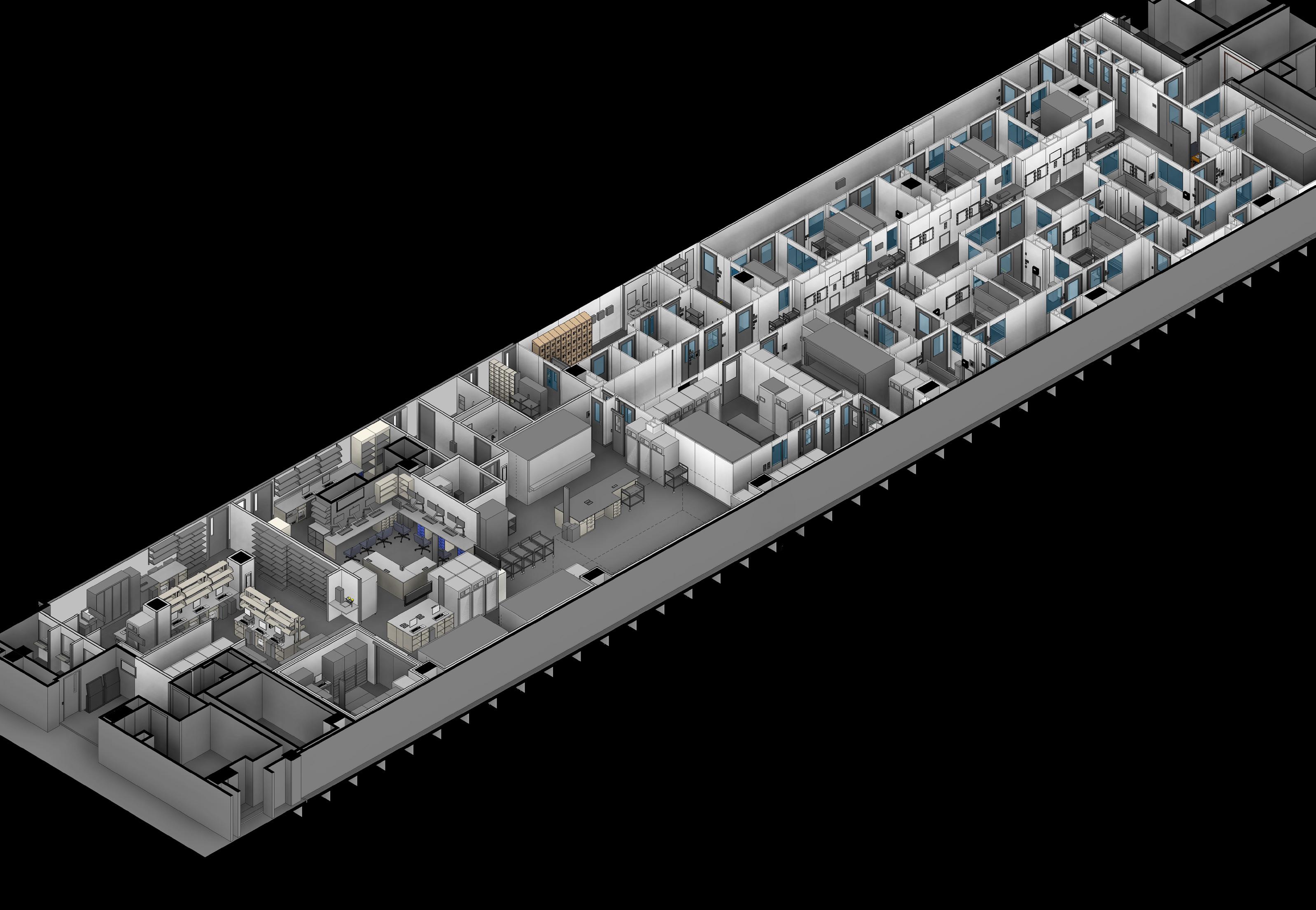
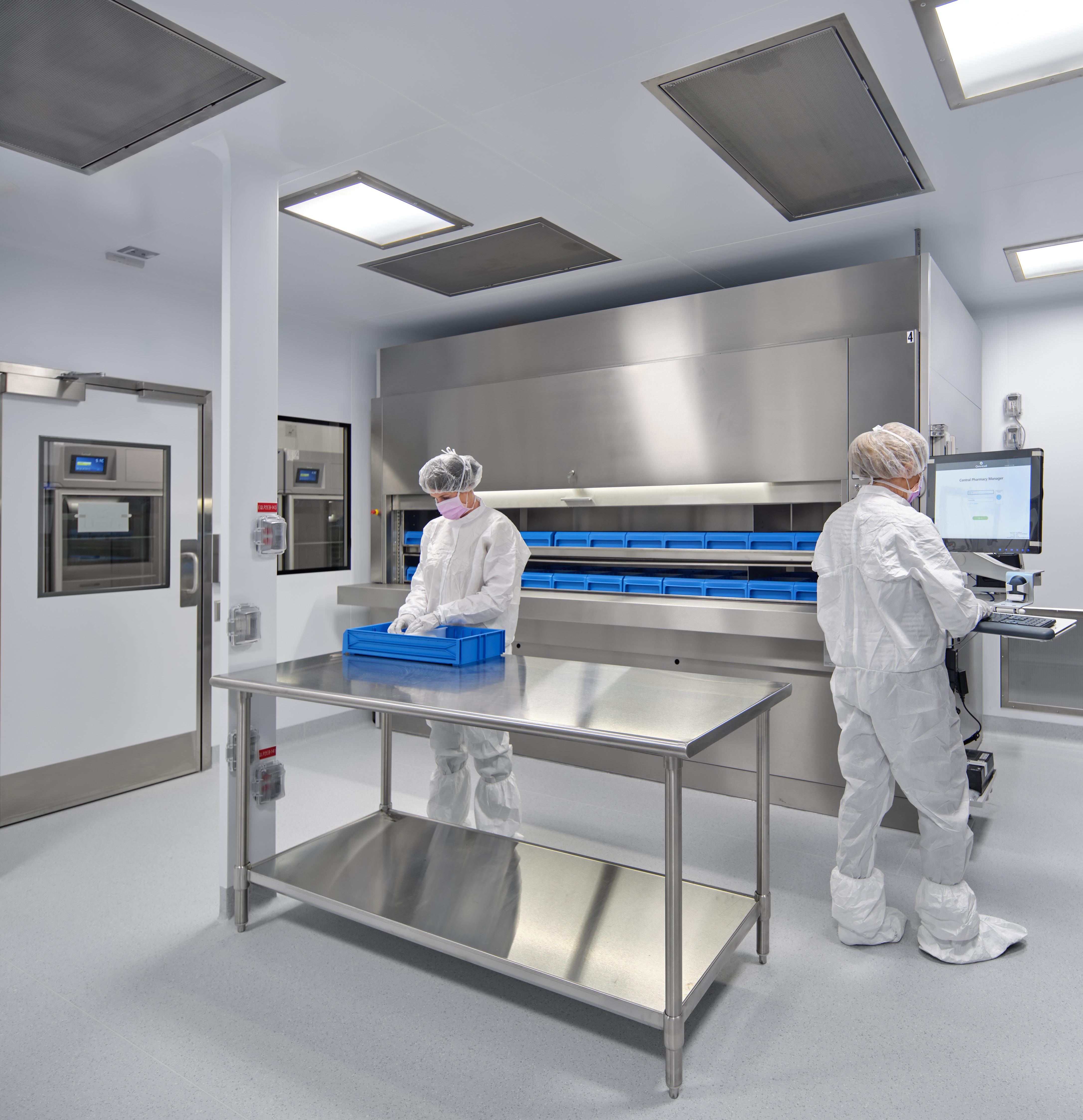
The two facilties making up the P-IVAU pharmacy are the Aseptic Production Facility (APF, shown on the page right half of the isometric) and Non-APF Pharmacy (shown on the left half). The design contributions toward the APF were the coordination between the disciplines (Architectural, MEP, and Low Voltage) and the modular cleanroom wall manufacturer (AES), and the selection/Coordination of the finishes.
CLEANROOM SUITES
USP 797 Cleanroom Suite (Sterile Compounding)
“Kitting” Rooms (Sterile assembly rooms for measuring and prepping ingredients)
USP 800 Cleanroom Suite (Hazardous Drug Compounding)
Aseptic production facility (APF) flow diagram— personnel flows 2
BSL-2 Cleanroom Suite (Biosafety Lab Level 2) (Pathogenic/infections organisms posing moderate health hazard)
aseptic production facility (APF) flow diagram— Product flows
The design team was responsible for understanding a complex set of requirements and constraints presented in the form of bridging documents. The pharmacy serves both inpatients and outpatients of the clinical center, and the team had to understand the flow of materials, personnel, waste, and products in the context of FDA requirements. 3
SURFACE MOUNTED MONITOR ENCLOSURE, TYP CUSTOM OPENING AT BACK OF THE MONITOR ENCLOSURE.
Voltage Raceway in Panelized CLean Room
CLEA NROOM COORDINATION
DATA RACEWAY, TYP POWER RACEWAY, TYP
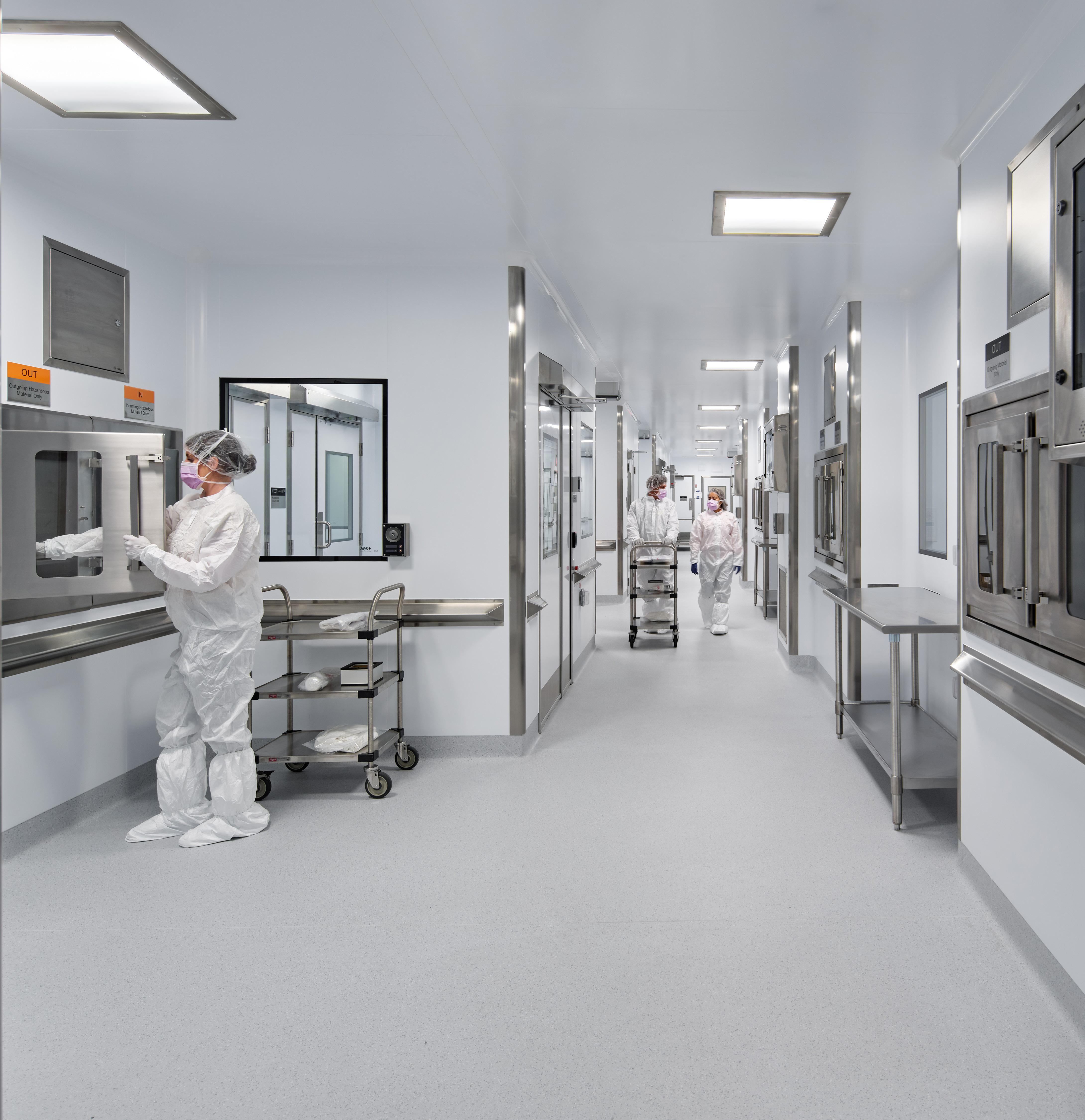
The APF pharmacy contains three compounding suites of USP 797, 800, and BSL-2 classifications. Understanding the unidirectional flow of personnel through airlocks and gowning rooms was critical in understanding the spatial organization of the facility and provided a foundation to the more complex requirements of cleanroom design.
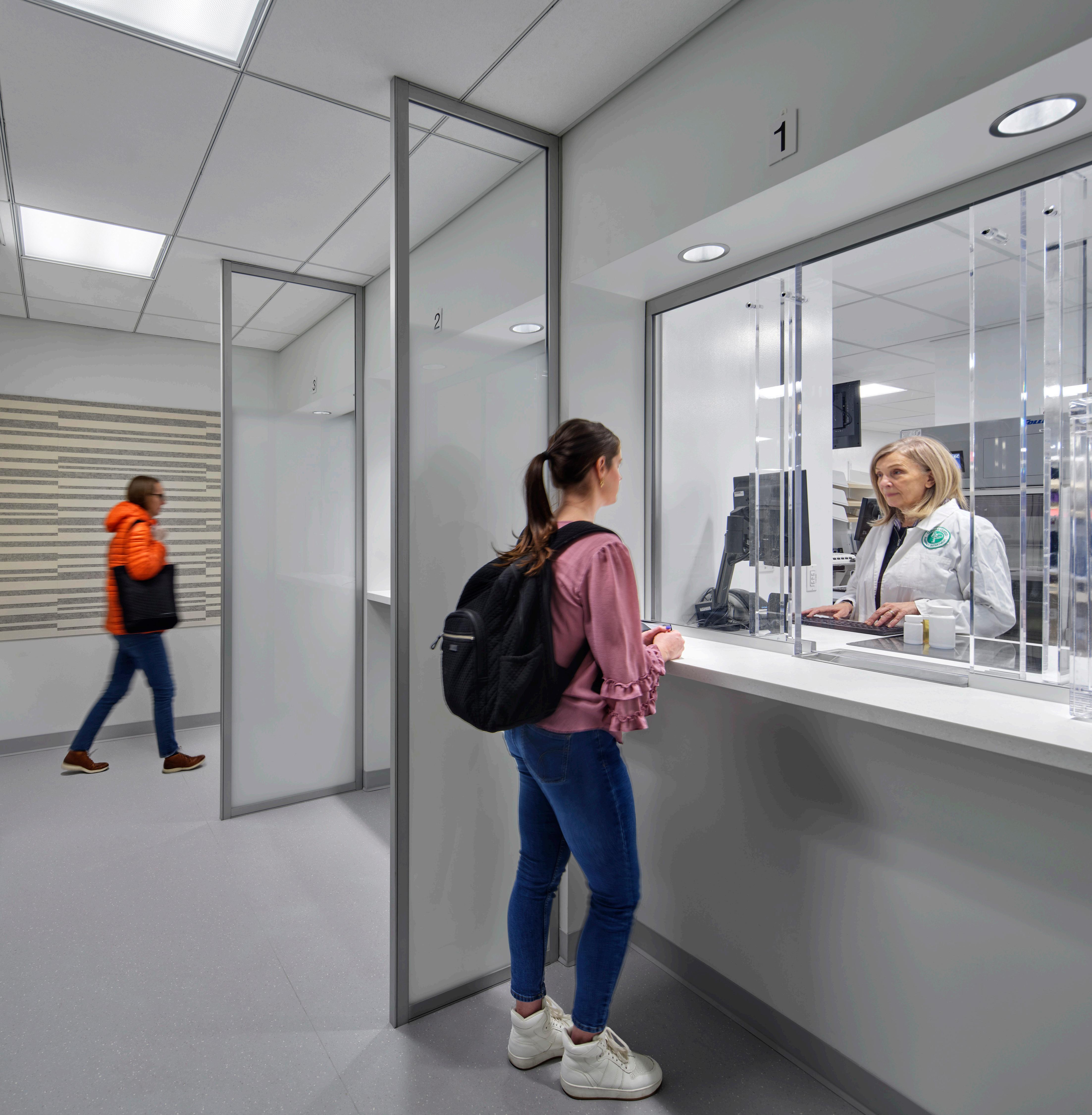
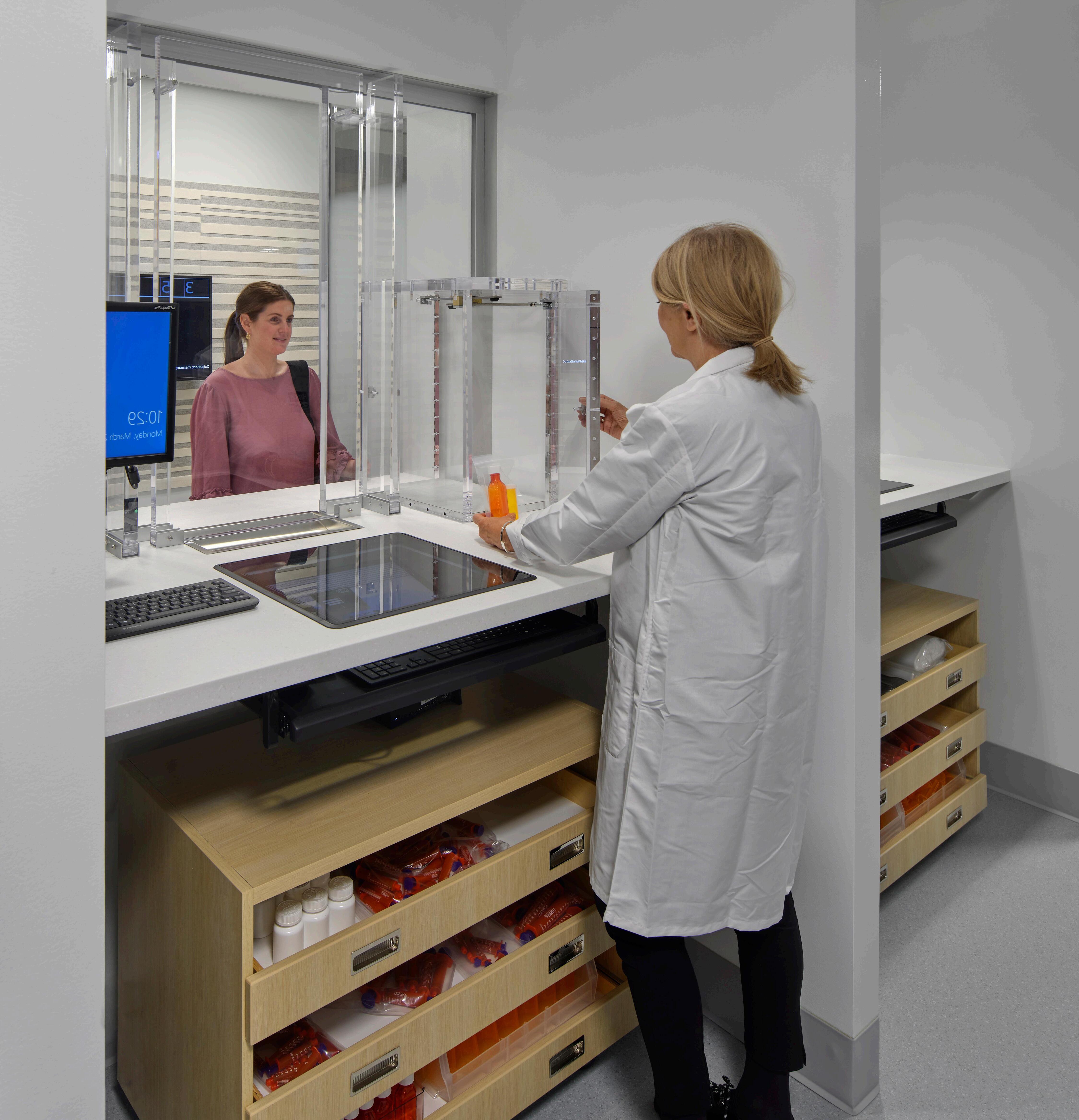
The limited space available for the outpatient check-in and pick-up required creative problem solving by the design team. A fire rated storefront system maintained transparency and increased visibility for the pharmacy. The pick-up transaction windows had to be coordinated between their multiple parts: Undercounter mounted monitors had to be
STUD FRAMING
STUD FRAMING
CHANNEL @
1 1/2" HEAVY GAGE HAT CHANNEL @ 16" O.C, TYP
FASTENERS PER WINDOW MANUFACTURER'S SPECIFICATIONS
1-3/4" x 4" ALUMINUM TUBE
FASTENERS PER WINDOW MANUFACTURER'S SPECIFICATIONS
CORNER BEAD PAINTED GYPSUM SOFFIT
1-3/4" x 4" ALUMINUM TUBE
SEALANT, TYP.
CORNER BEAD PAINTED GYPSUM SOFFIT
SEALANT, TYP.
ALUMINUM 2-PC CHANNEL UL RATED BULLET RESISTANT GLAZING
METAL ANGLE AT WALL BEYOND, PROVIDE STRAPPING AS NECESSARY
COUNTERSUNK FASTENERS PER STL BRACKET MFR
2"X2"X1/4" STEEL TUBE. SEE 12/AG0.21, TYP.
METAL ANGLE AT WALL BEYOND, PROVIDE STRAPPING AS NECESSARY
PARTIAL HEIGHT PARTITION WITH 4" STUD FRAMING
2"X2"X1/4" STEEL TUBE. SEE 12/AG0.21, TYP.
PARTIAL HEIGHT PARTITION WITH 4" STUD FRAMING
NOTE: COUNTERTOP SUPPORT TO COMPLY WITH COUNTERTOP MFR REQUIREMENTS
NOTE: COUNTERTOP SUPPORT TO COMPLY WITH COUNTERTOP MFR REQUIREMENTS
PHARMACIST SIDE
Because of the afoermentioned constrainted, the design team was confronted with a design challenge on how to frame and support the transaction windows. The solution was to set the windows upon a half-wall with steel supports. The windows are fastened to a bulkhead above, with light gauge ‘kickers for lateral stability.
The design team proposed utilizing acrylic passer boxes, which were available from the security window manufacturer. The selection helped maintain transparency between patients and the pharmacists while providing the security that was important to the client The complexity of the windows required significant care and attention to detail.
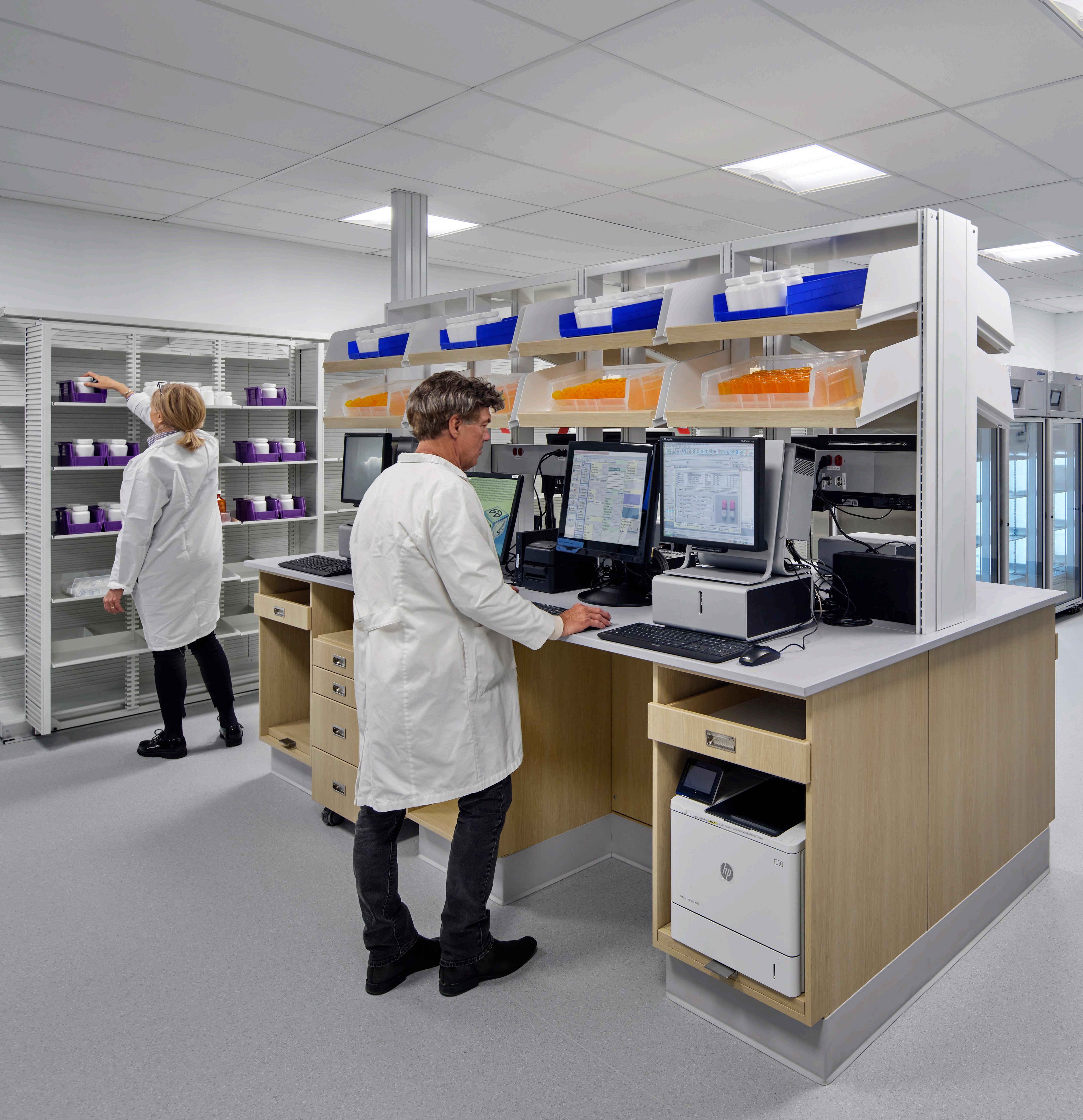
PHARMACY CASEWORK
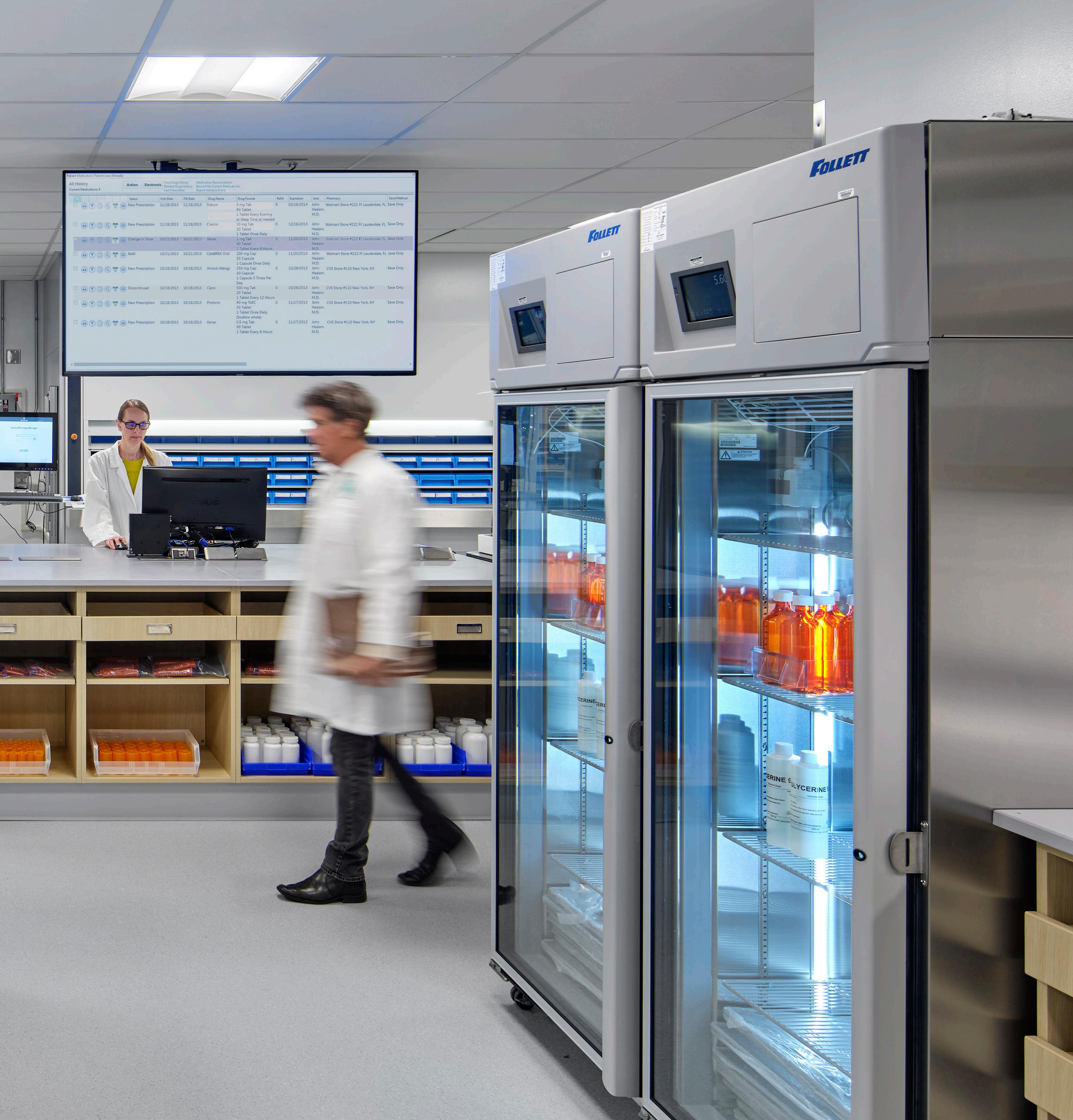
Medication dispensing and inventory control for inpatient, outpatient, and mail-away prescriptions are among the primary functions of the non-APF portion of the pharmacy, and thus understanding the power and data requirements for automated inventory and dispensing equipment was critical to the design and coordination of the pharmacy casework.
POWER/DATA RACEWAYS UPRIGHT POST EDGE OF BENCHTOP POWER POLES
UPRIGHT STANCHION, TYP.
CONTINUOUS POWER/DATA RACEWAYS, SEE ELECTRICAL
POWER POLE EPOXY COUNTERTOP
ELECTRICAL CONDUIT, SEE ELECTRICAL, TYP.
3" 75 1' - 0" TYP 305 TYP
POWER POLE BOTTOM CLOSURE
CONDUIT STUB-UP
COVER PLATE, TYP.
UPRIGHT FRAME, TYP.
DATA CONDUIT, SEE ELEC, TYP. Plan Diagram—Conduit Stub-up
Diagram—Conduit Stub-up
E2
E1
Pharmacy Tech Work Station
Technical detailing helped overcome challenges around minimum conduit bend radiuses. Power and data conduits are fed through power poles, into the cores of the tech islands, and up through conduit stub-ups concealed between the upright stanchions. These stub-ups had to be closed for an attractive appearance, but also cleanability requirements.
This project was a multifaceted documentation exercise with increased design sensitivity. It was a beneficial learning experience that bestows a working knowledge of science in tech. Issues were working within an existing conditions (an operational clinical center), designbuild project delivery, critical issues around clean room design, project coordination, constructability, and increased familiarity with the
design and material requirements of pharmacies, pharmacy operations, and cutting edge pharmaceutical equipment. This project phases involved were design development (DD), construction documents (CA), and construction administration (CA).
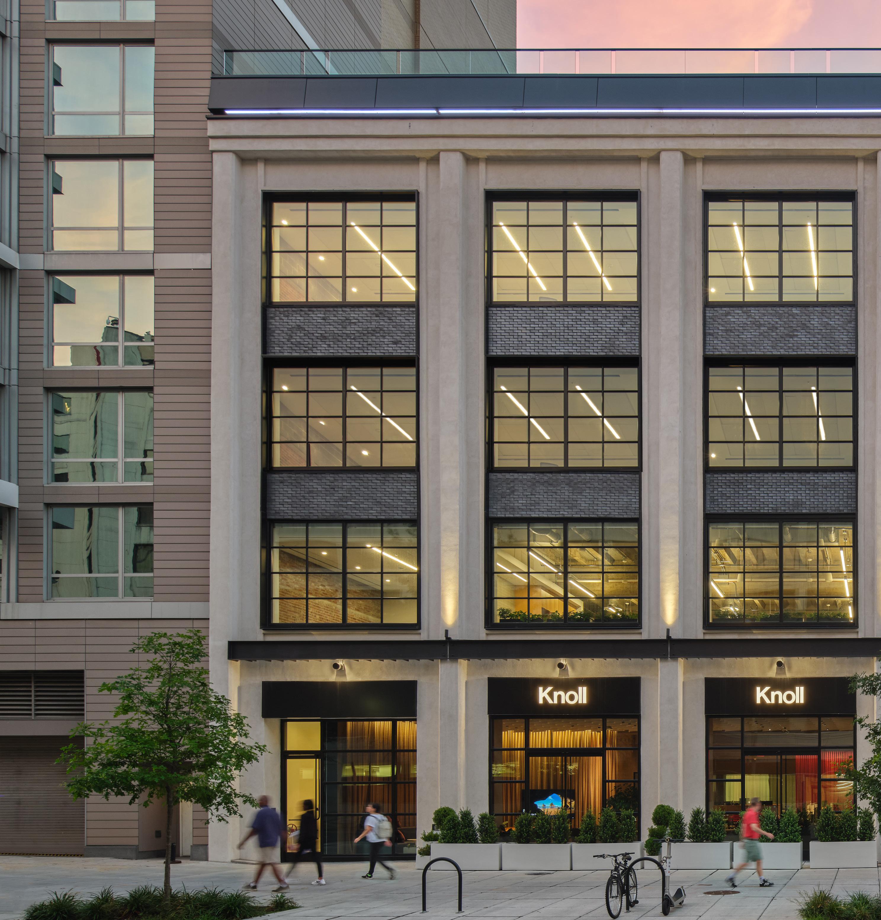
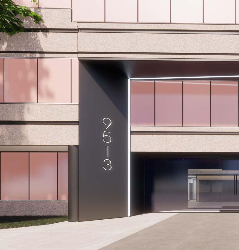
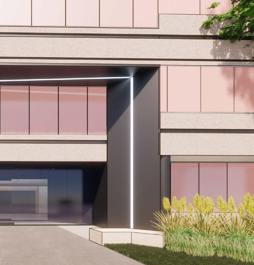
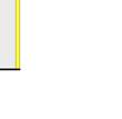
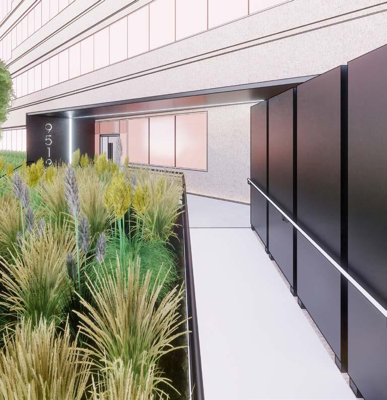
EAST ENTRY GATEWAY
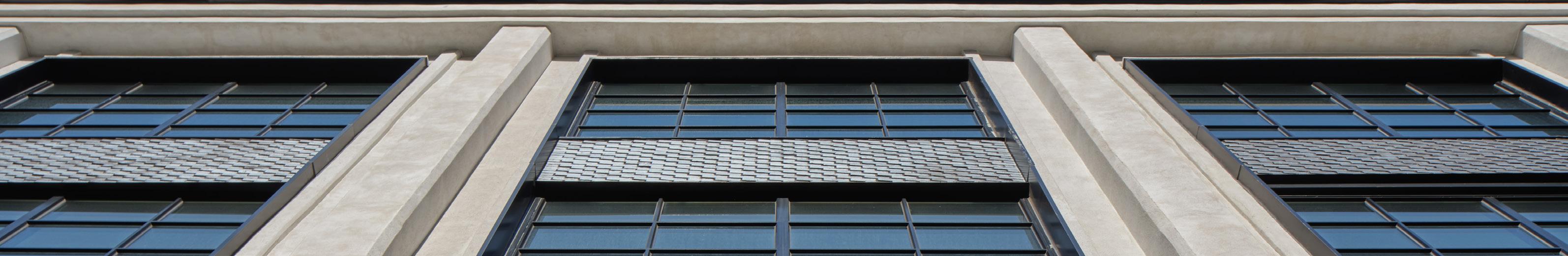
One primary architectural elements of the shell renovation was an ACM Panel gateway at the buildings main entrance. The details of the monolothic gateway were considered beginning in Design Development (DD) and finalized in the Contract Document (CD) package. Working with the existing conditions, portions of the existing second floor ribbon windows were designed to be removed and
CONCRETE CURB, SEE STRUCT EXTERIOR METAL PANEL, WT-2
CONCRETE CURB, SEE STRUCT EXTERIOR METAL PANEL, WT-2
CONCRETE CURB, SEE STRUCT EXTERIOR METAL PANEL, WT-2 LAP AIR BARRIER OVER FLASHING DRIP EDGE, TYP
LAP AIR BARRIER OVER FLASHING DRIP EDGE, TYP
LAP AIR BARRIER OVER FLASHING DRIP EDGE, TYP
PAVERS NIC, SUBMITTED UNDER SEPARATE PERMIT, TYP.
PAVERS NIC, SUBMITTED UNDER SEPARATE PERMIT, TYP.
EXISTING CONCRETE SLAB
EXISTING CONCRETE SLAB
PAVERS NIC, SUBMITTED UNDER SEPARATE PERMIT, TYP. EXISTING CONCRETE SLAB
infilled with cold formed metal framing (CFMF). On the ground level, a concrete curb was designed to improve the performance by avoiding contact with water on the walking surface.
Careful consideration of panelization joints in the ACM panels helped made the design constructable.
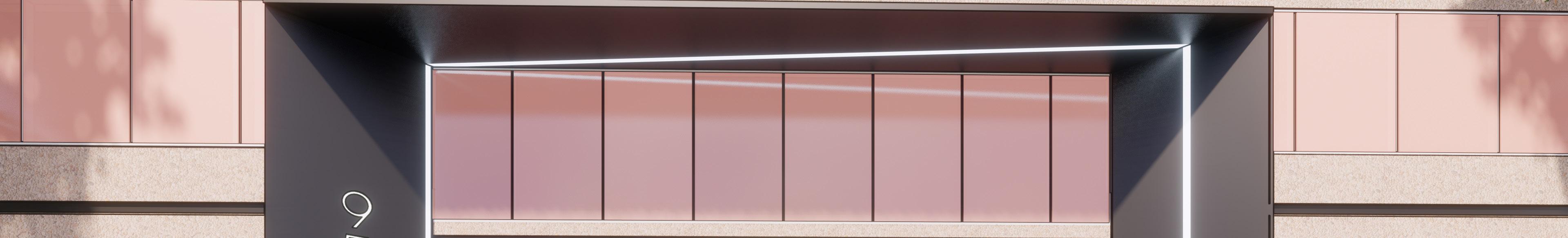
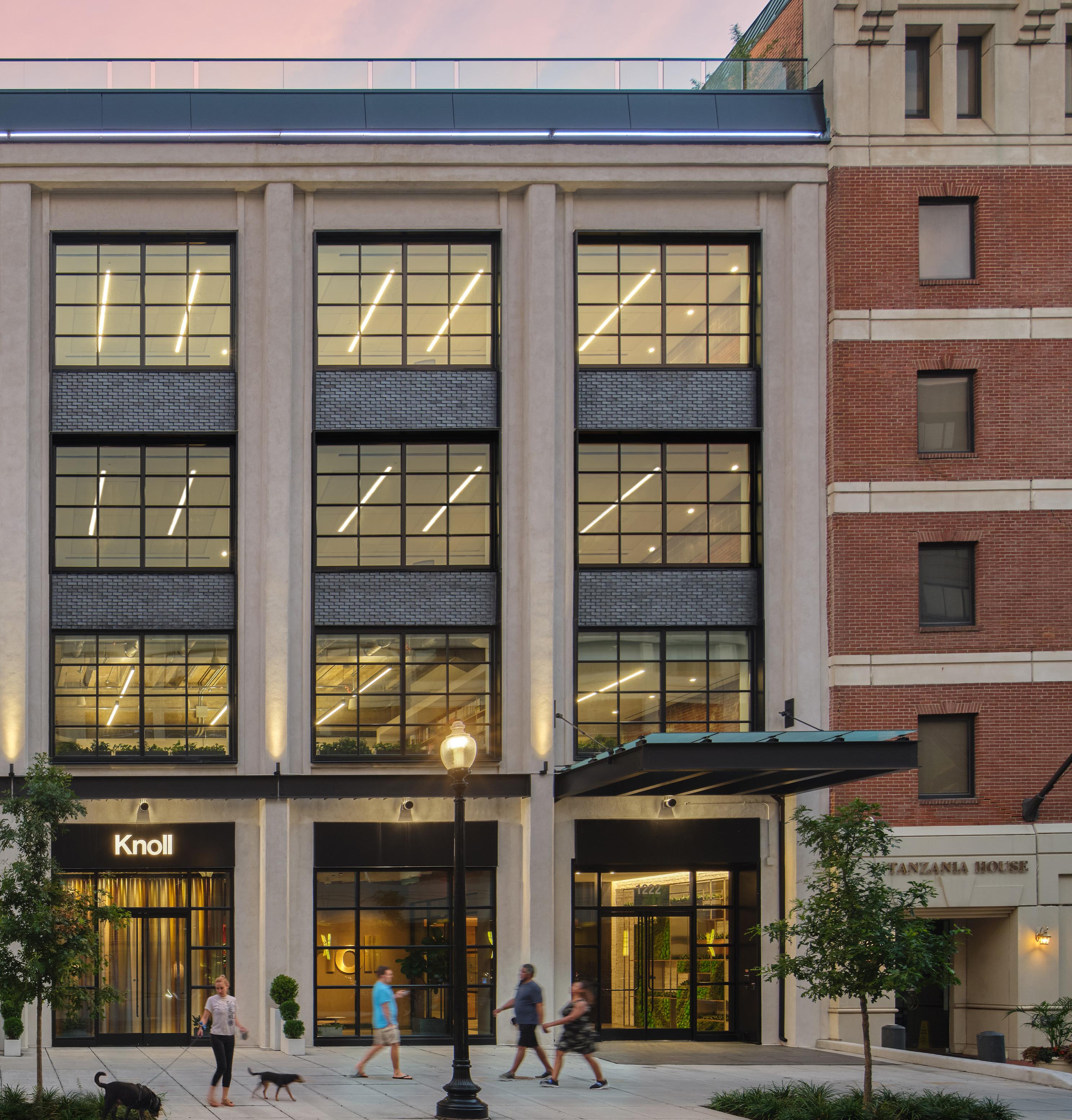
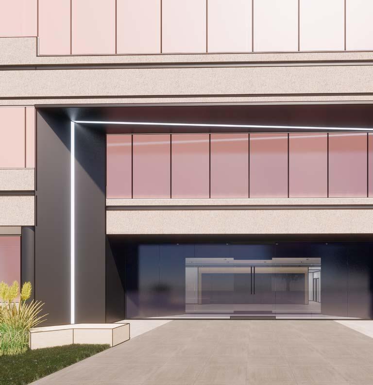
WEST ENTRY GATEWAY
Detailing a similar entry at the back (west entry) of the building was equally as crucial. Schematic renders show a paper-thin entry canopy with similar design language of the recessed linear LED light beaming across the vertical and horizontal planes. Details developed in DD and CD helped translate the schematic design into a set of buildable details.
Main consinderations were around structure and water. Details had to account for the thickness of structural steel (by delegated design) and CFMF, the aesthetic implications of sloping the canopy roof to shed water, and how the structure of the designed canopy relates to the existing building, including anchoring, flashing and sealing.
WEST ENTRY GATEWAY
Simialr to the East Entry gateway, similar constraints of the ACM panels were considered in the detailing. Maximum panel size and the maximum number of corners (2 max) informed the Reflected ceiling plan (RCP), sections, and details. Because the canopy had to shed water, the canopies leading edge features an internal gutter clad by a brake metal cover to blend in with
West Entry Canopy Section
the rest of the canopy. The gutter slopes to the north end of the canopy where an internal downspout channels the rain water down to ground level, where it is daylighted out of a “lambs tongue” style downspout nozzle into an adjacent planting bed.
1/2" Steel Plate fastened to Underside of structural steel
Detail 5
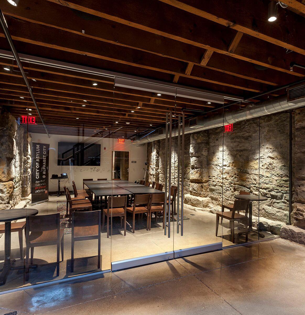
Ceiling Plan—Basement
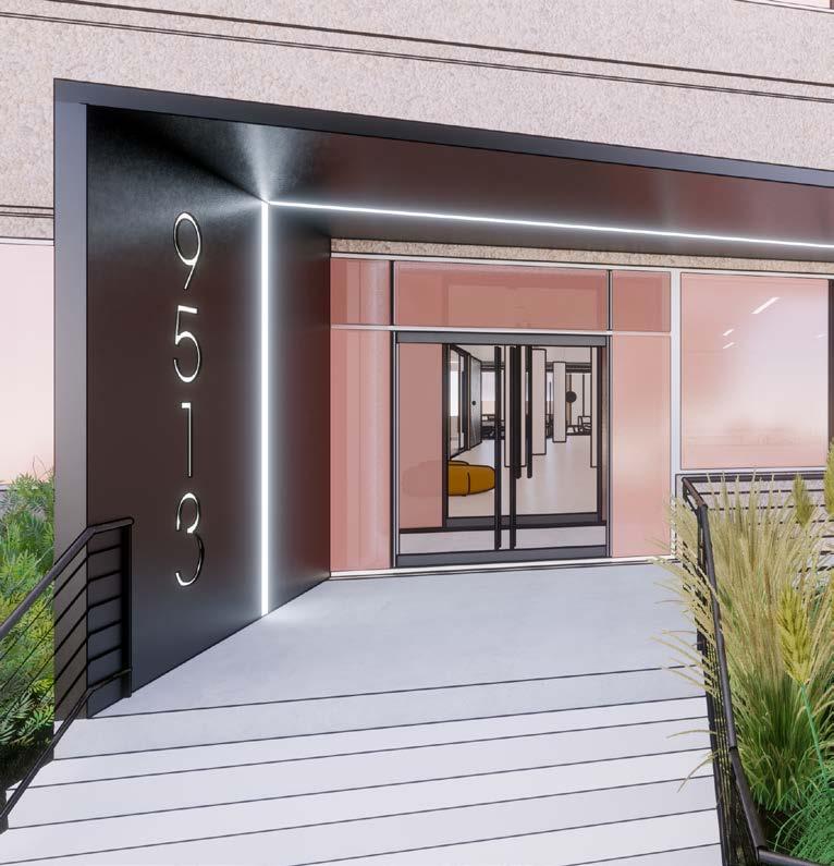
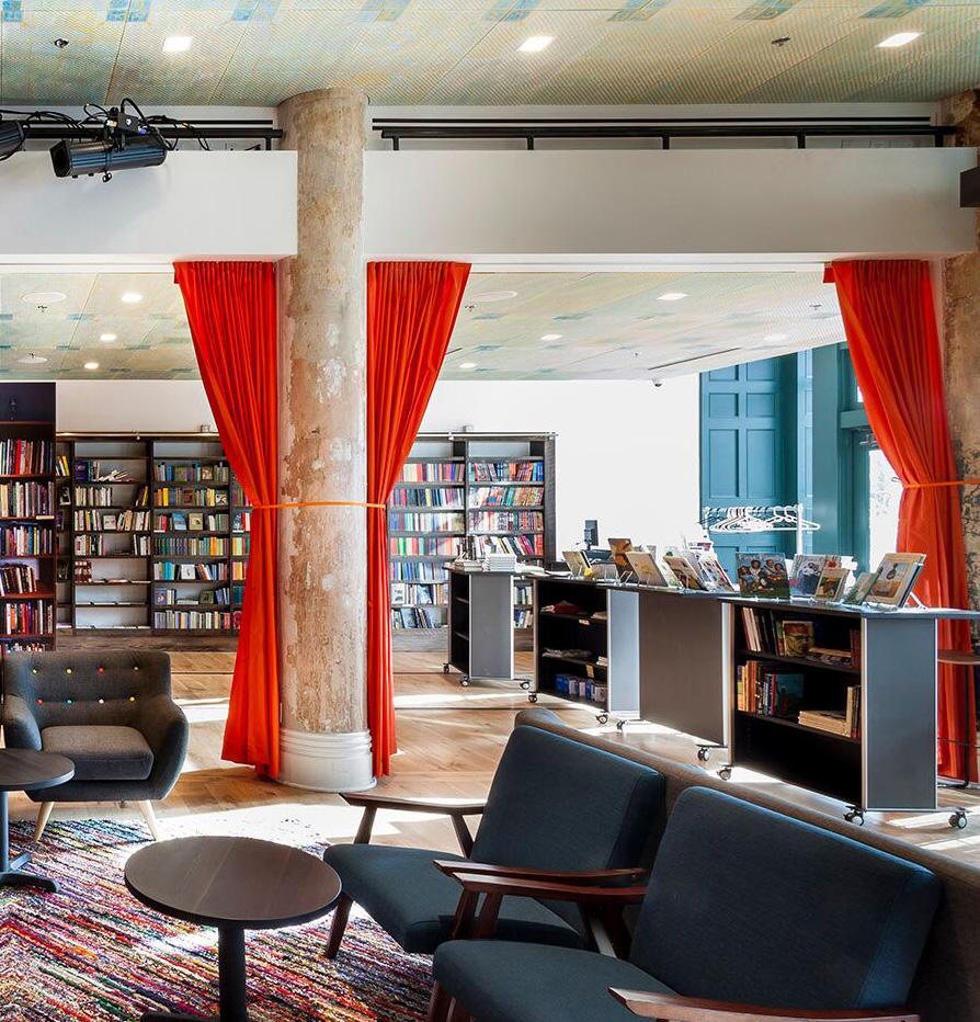
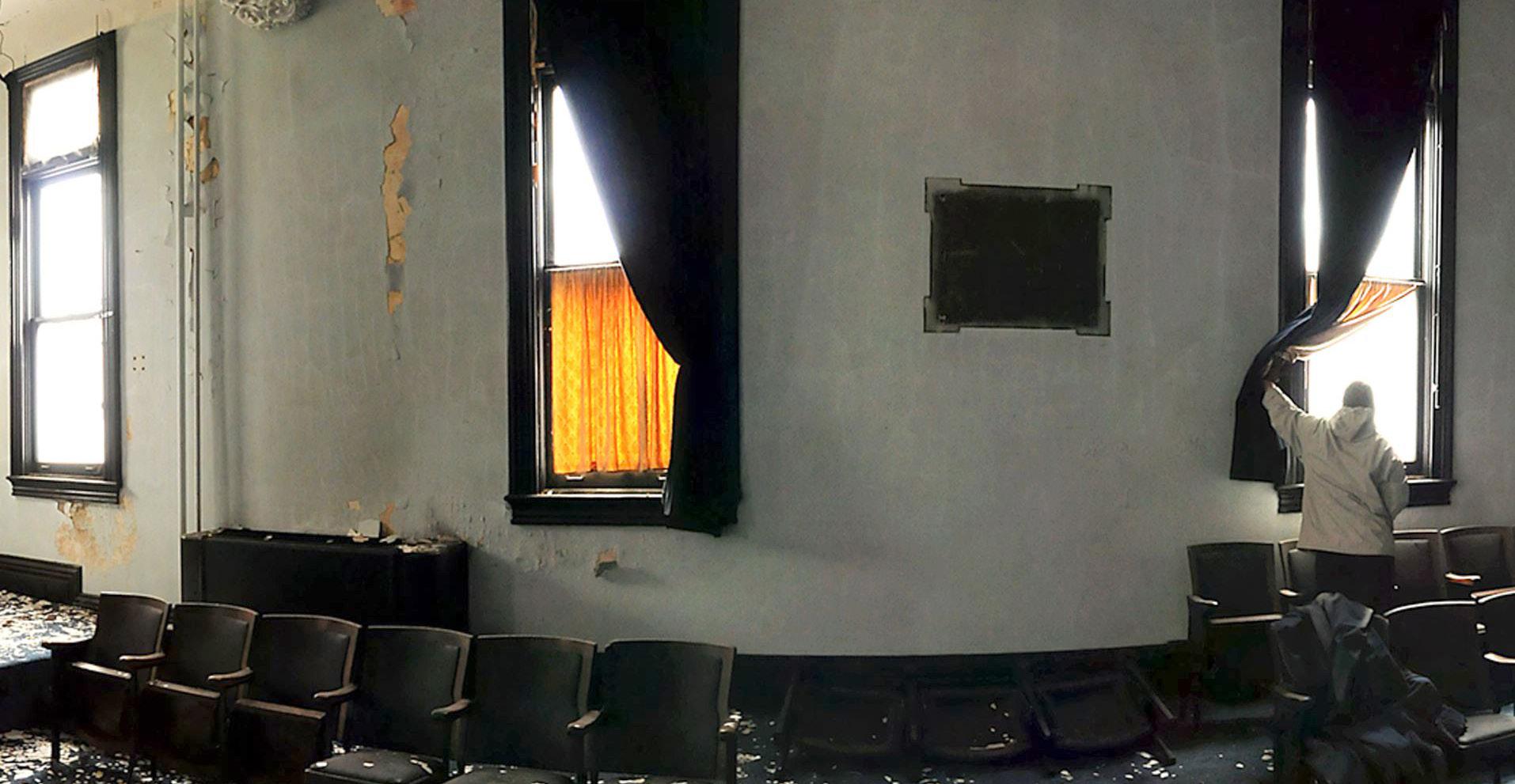
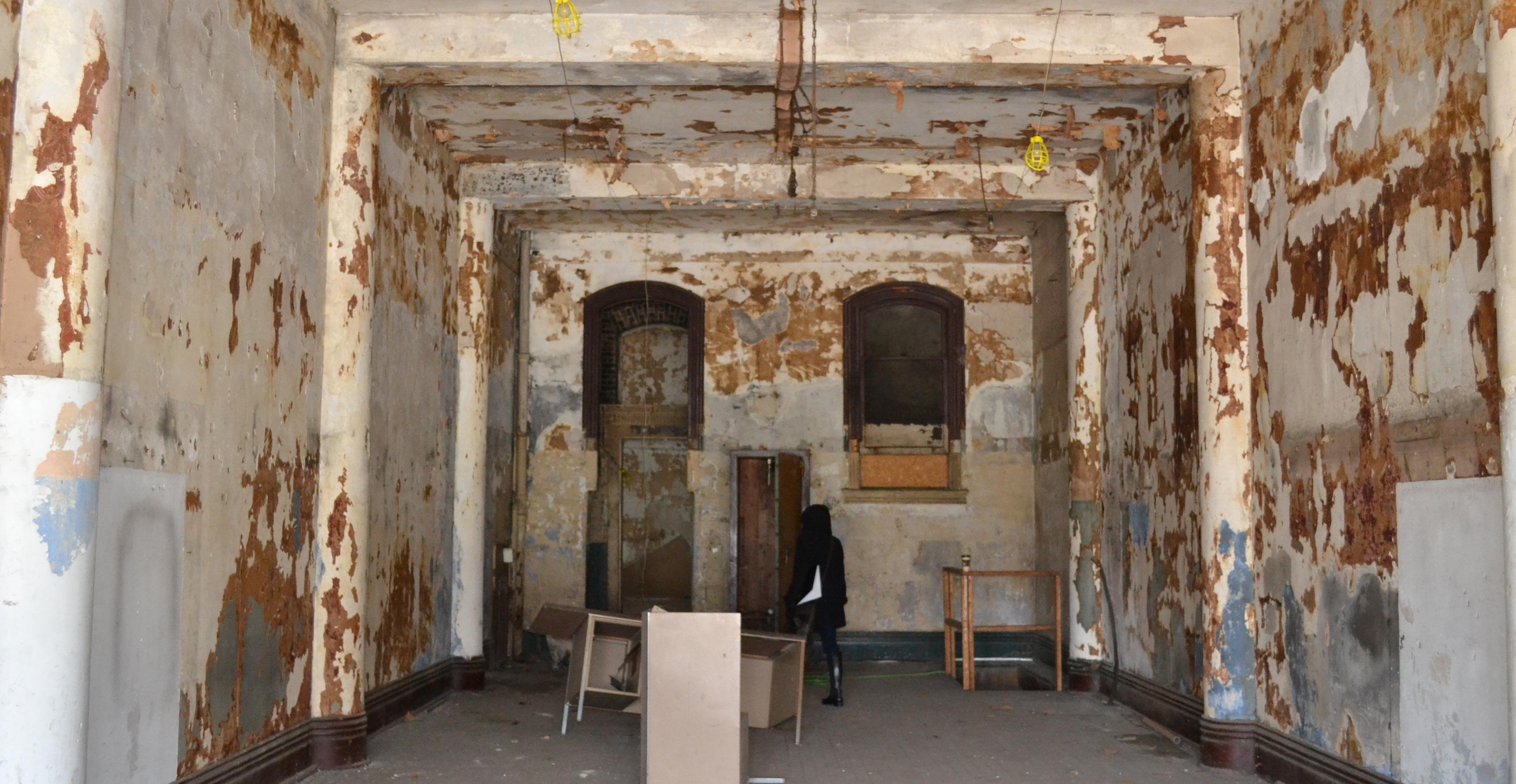
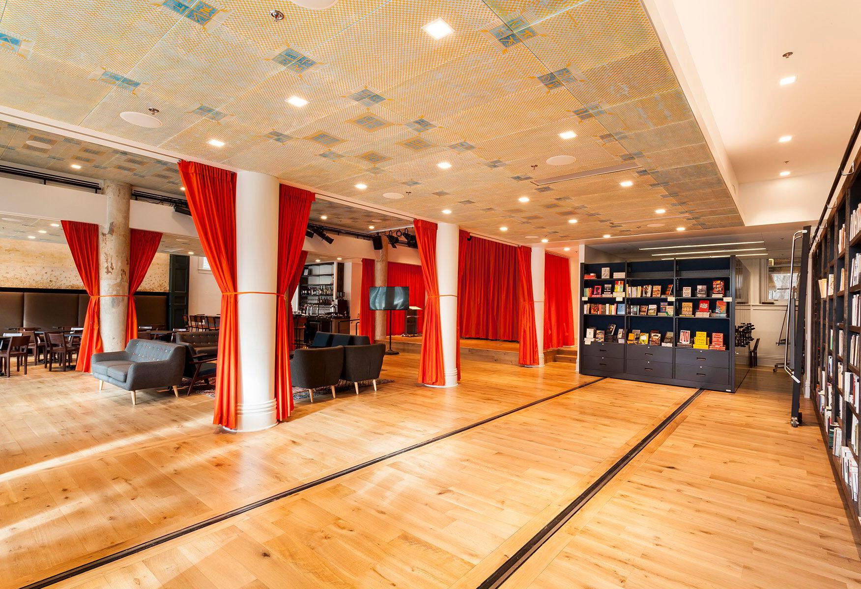
A rentable conference room, along with the organization’s offices, and the prep kitchen for the restaurant were located in the basement. The original basement had a clearance of about 6’-0”. The existing foundations had to be underpinned to allow a
for the occupants as well as flexibility for the mechanical and electrical quipment. The existing masonry of the
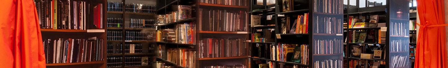
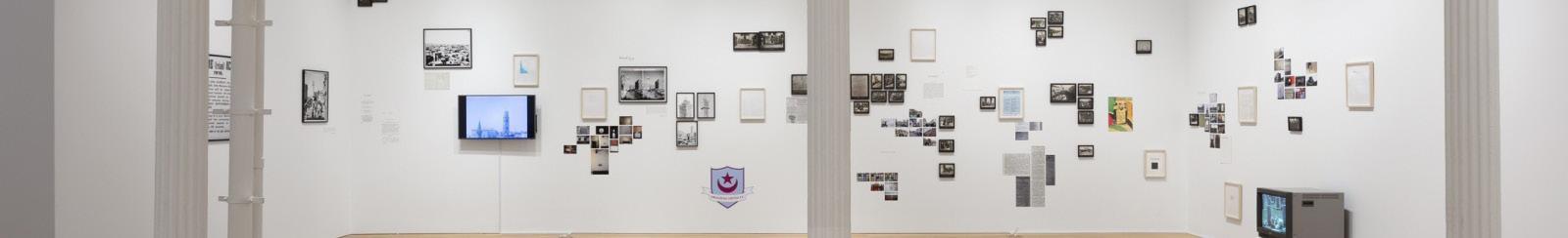
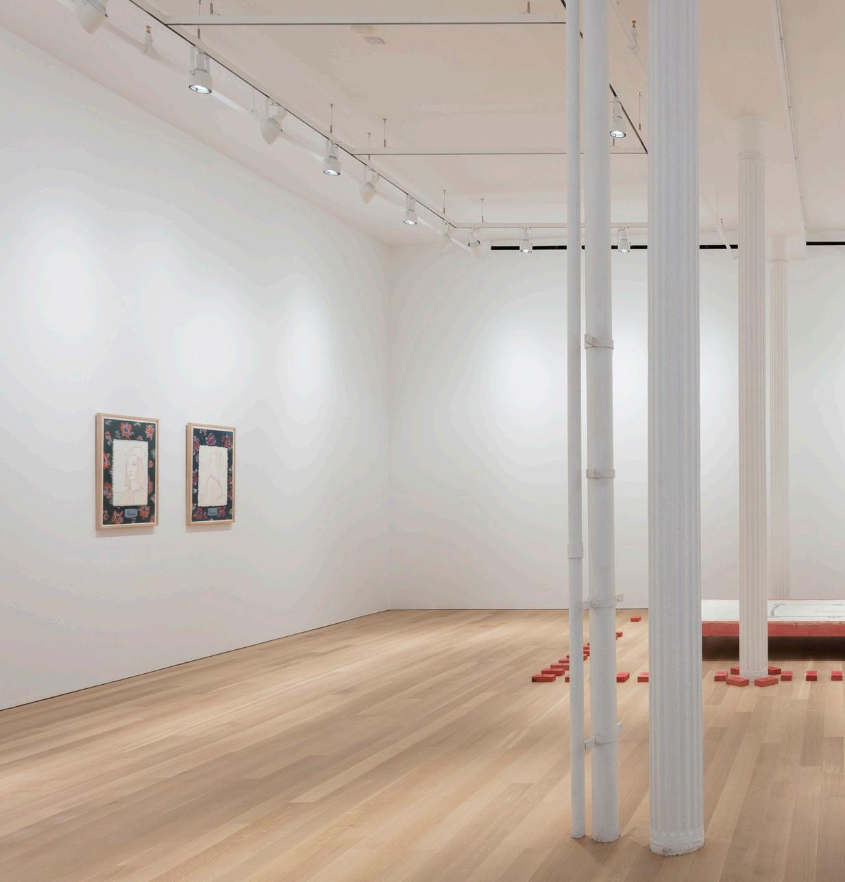
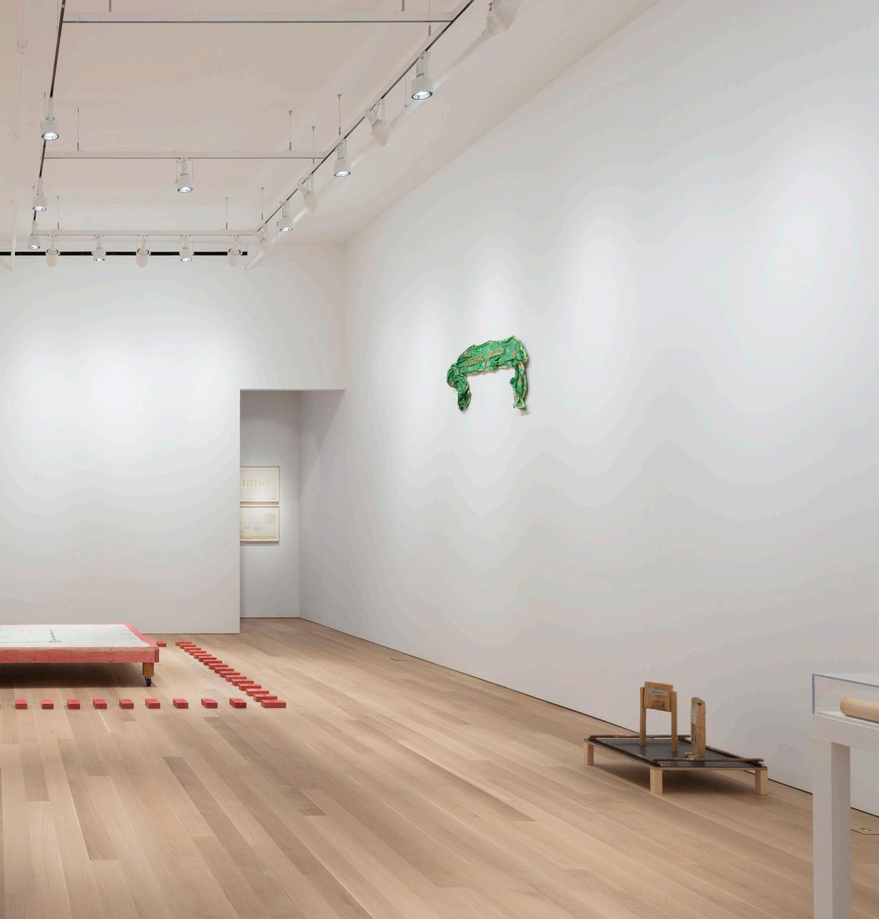
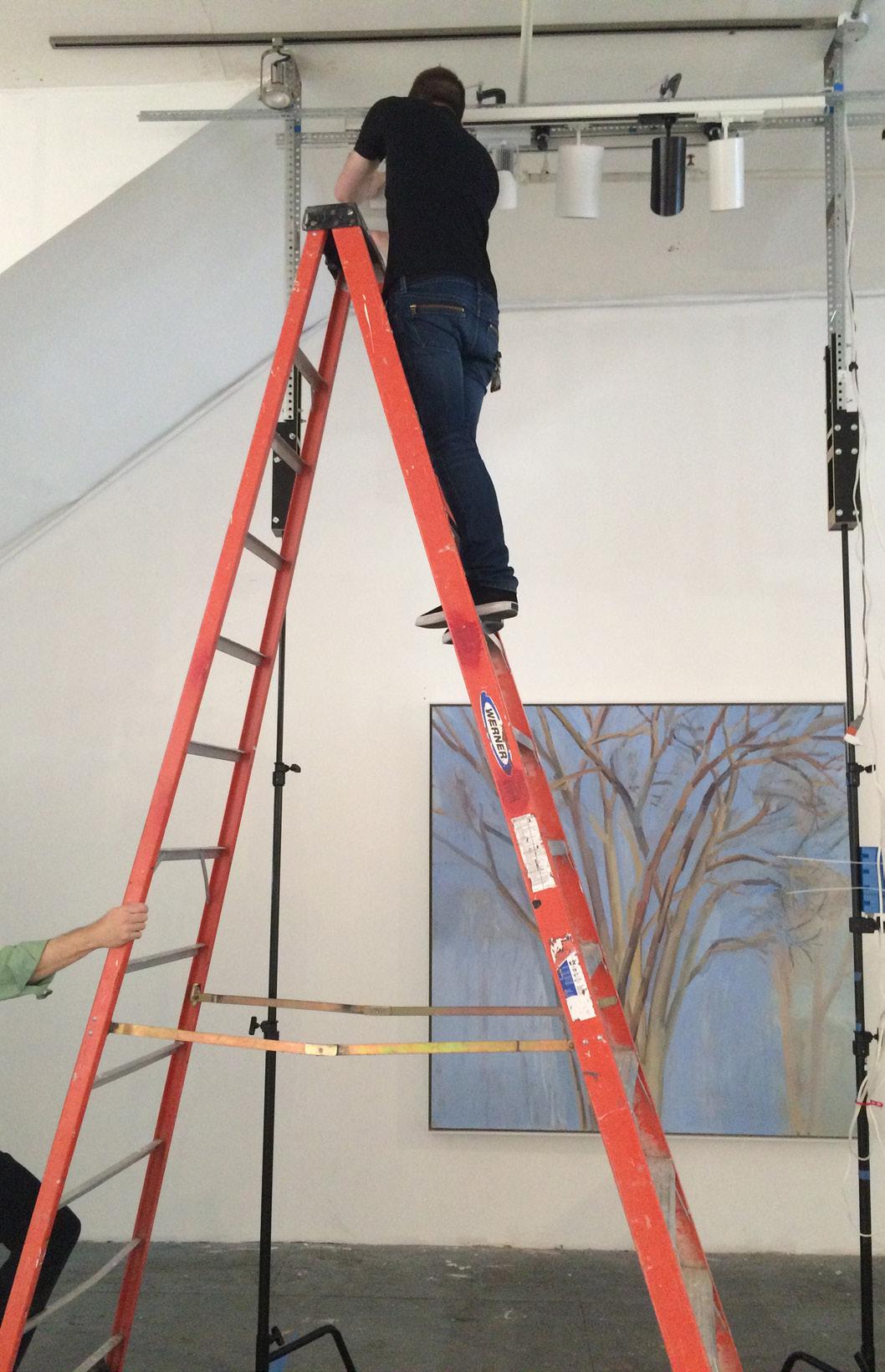
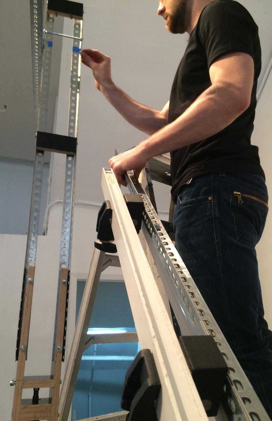
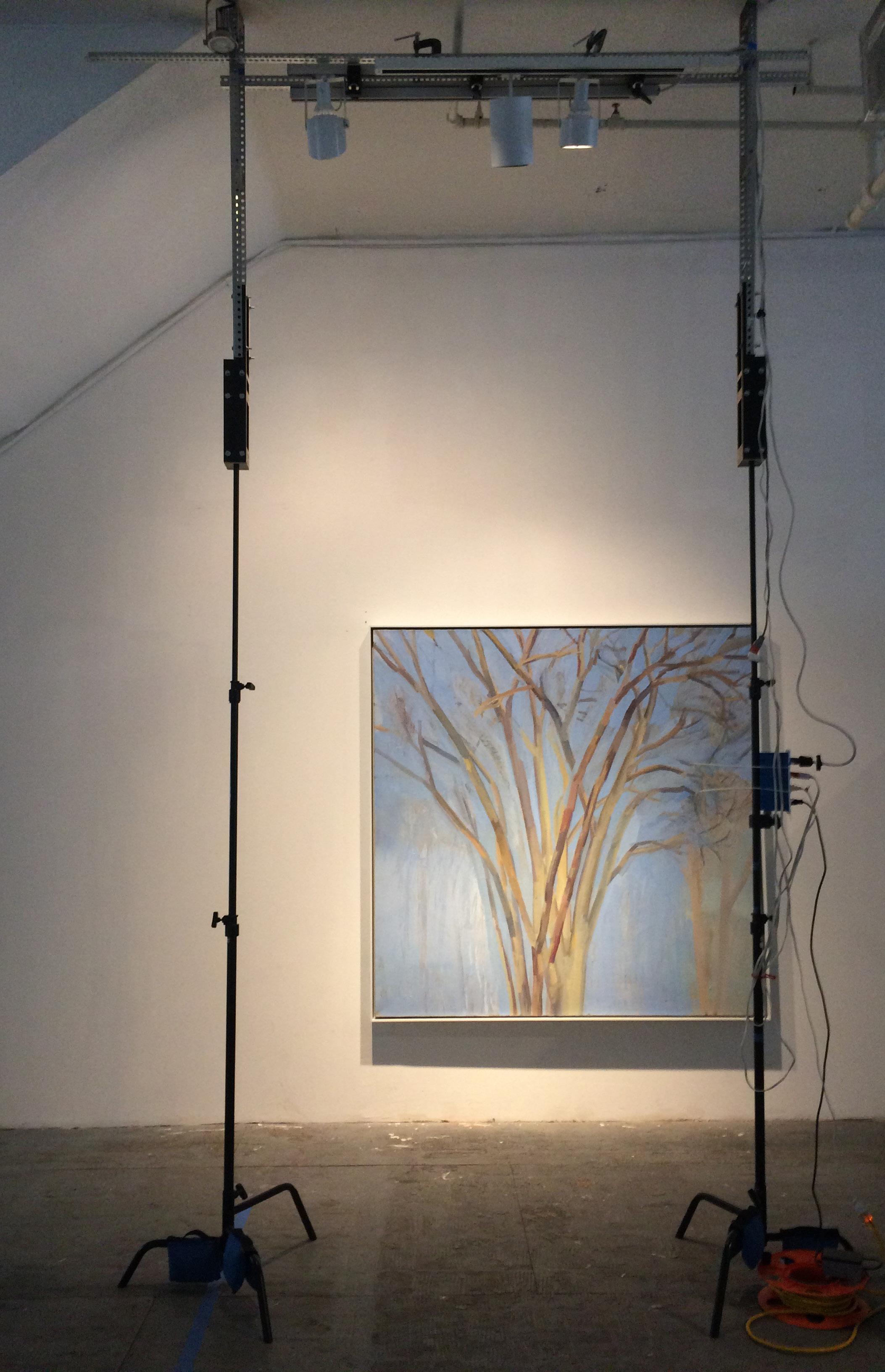
Lightining from too steep or shallow of an angle can result in undesirable glare. To locate the ideal fixture placements on the architectural RCP, the process started by understanding and applying the typical eye level of 5’ - 4” and the rules of thumb being between 33–36° to light art and avoid glare. Coordinating with the ceiling height, ideal fixture locations were mapped onto an RCP and shared with the architects.
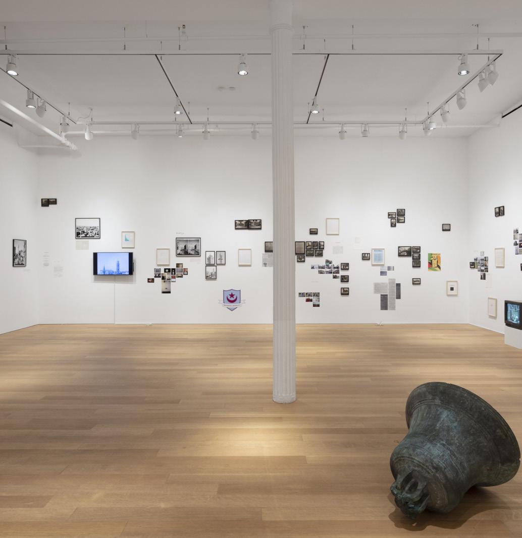
COMPLETION
The project was completed in 2016. The gallery has a flexible option for track heads that allows the gallery to curate the best possible exhibitions.
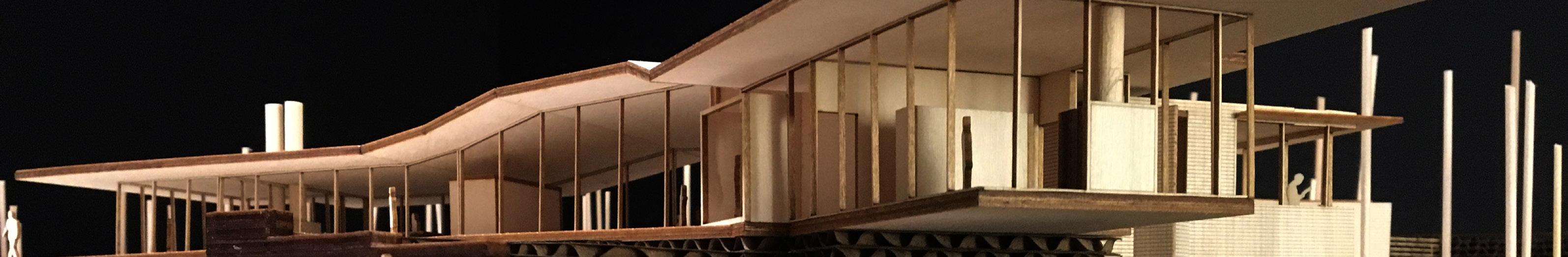
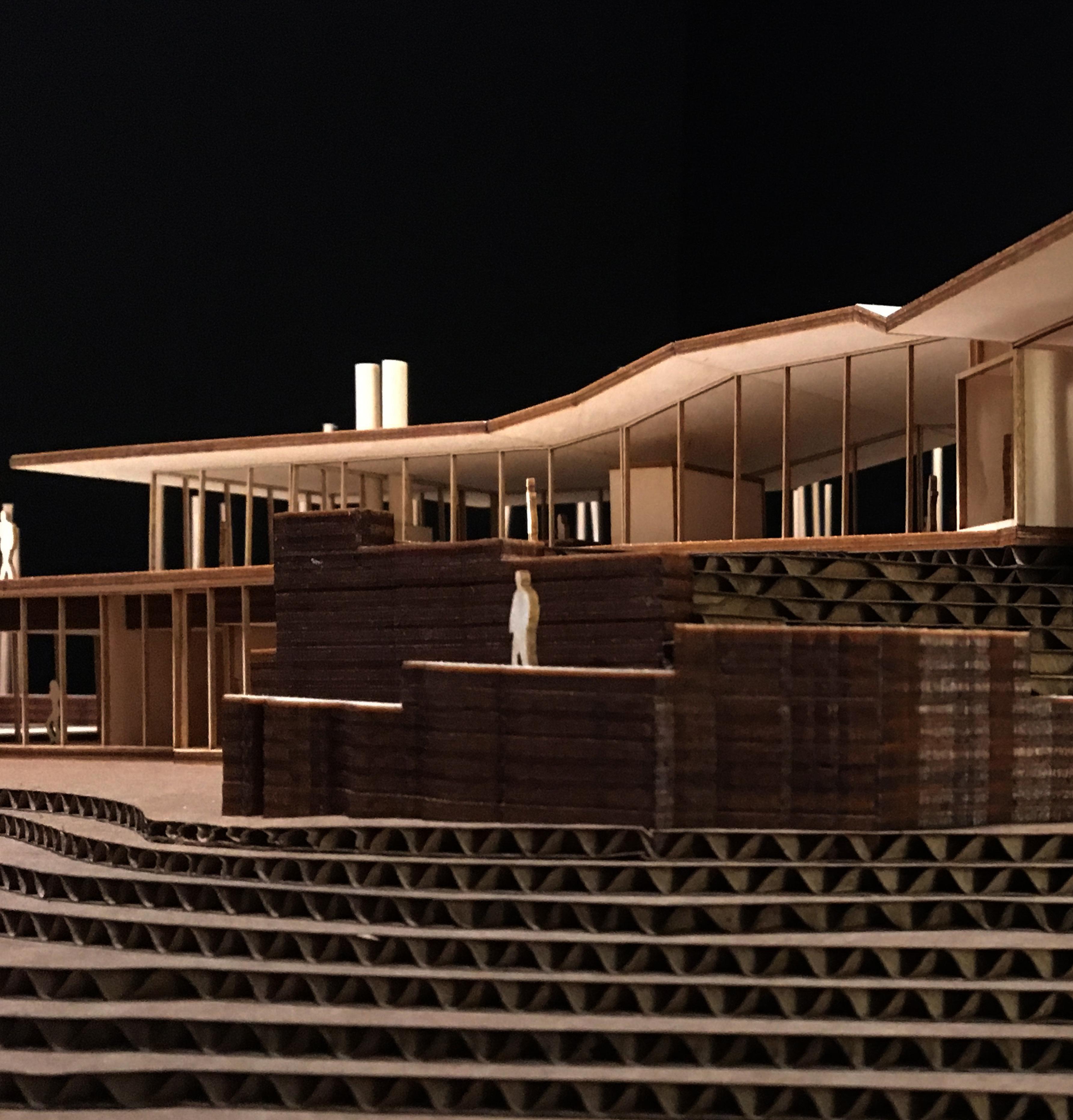
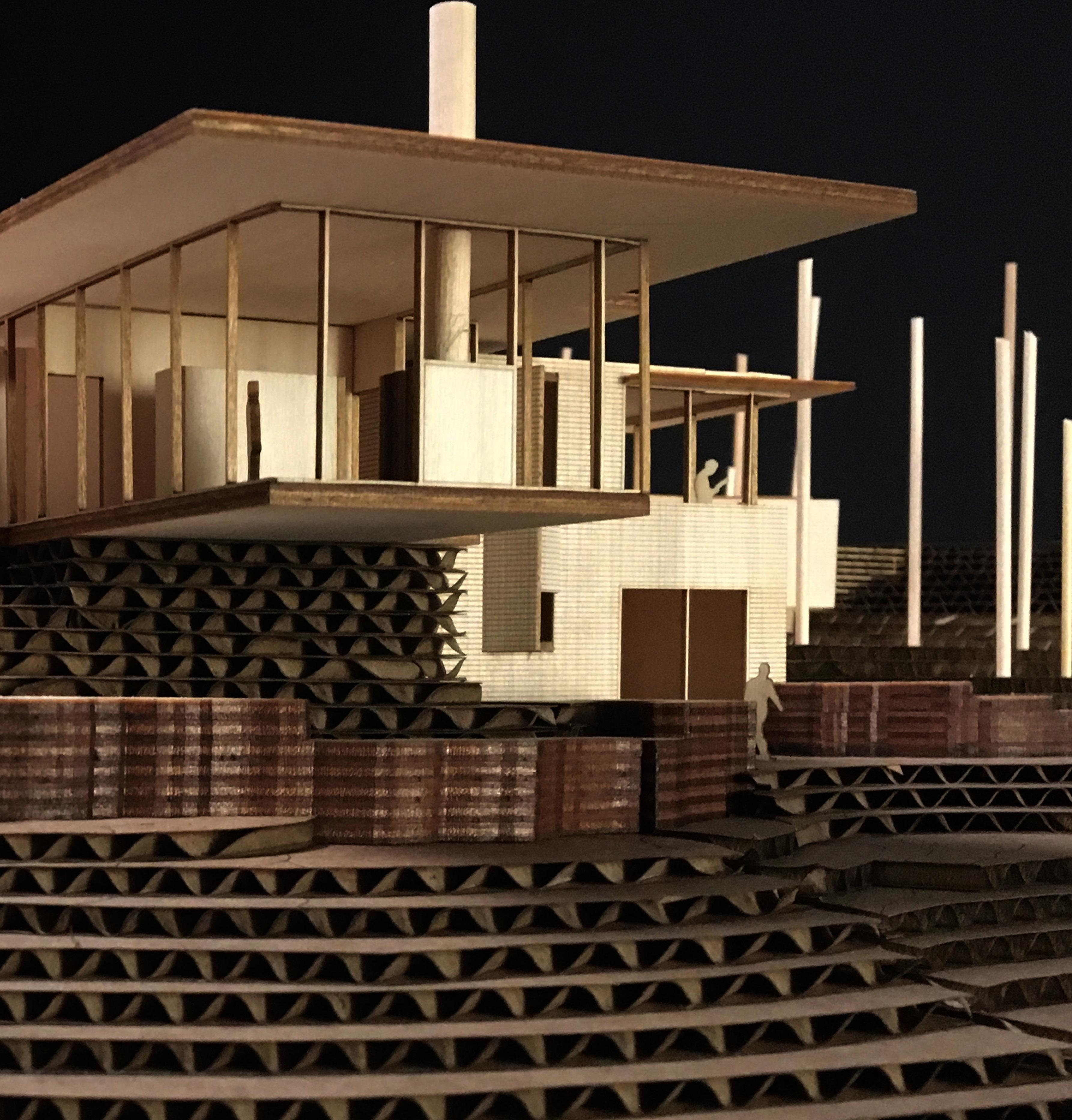
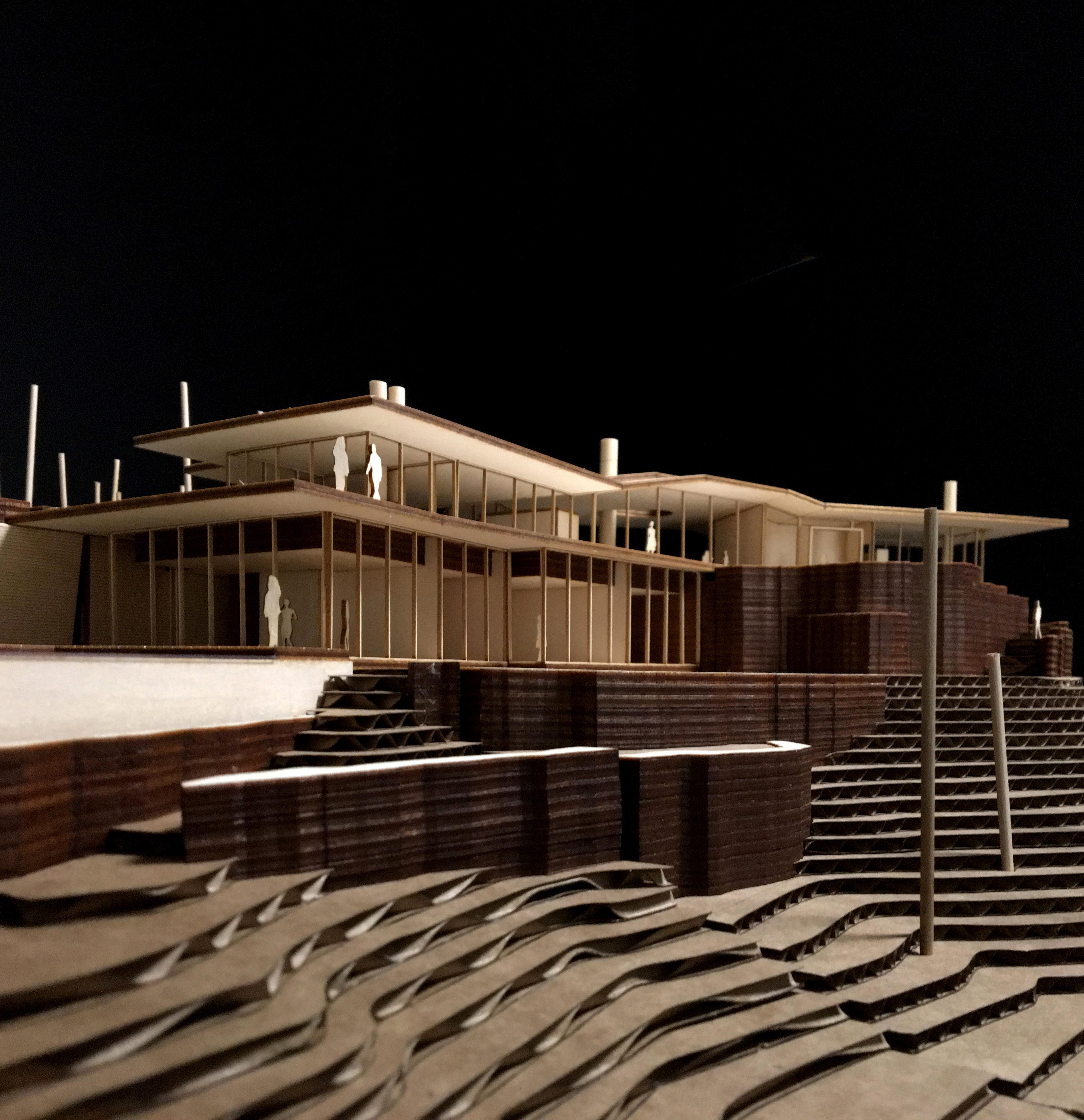
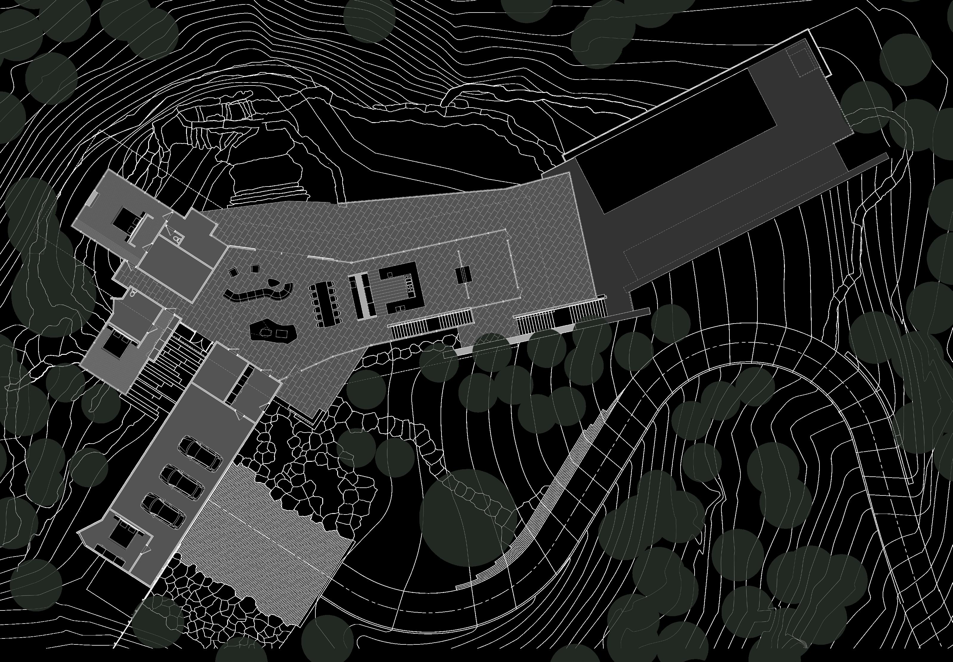
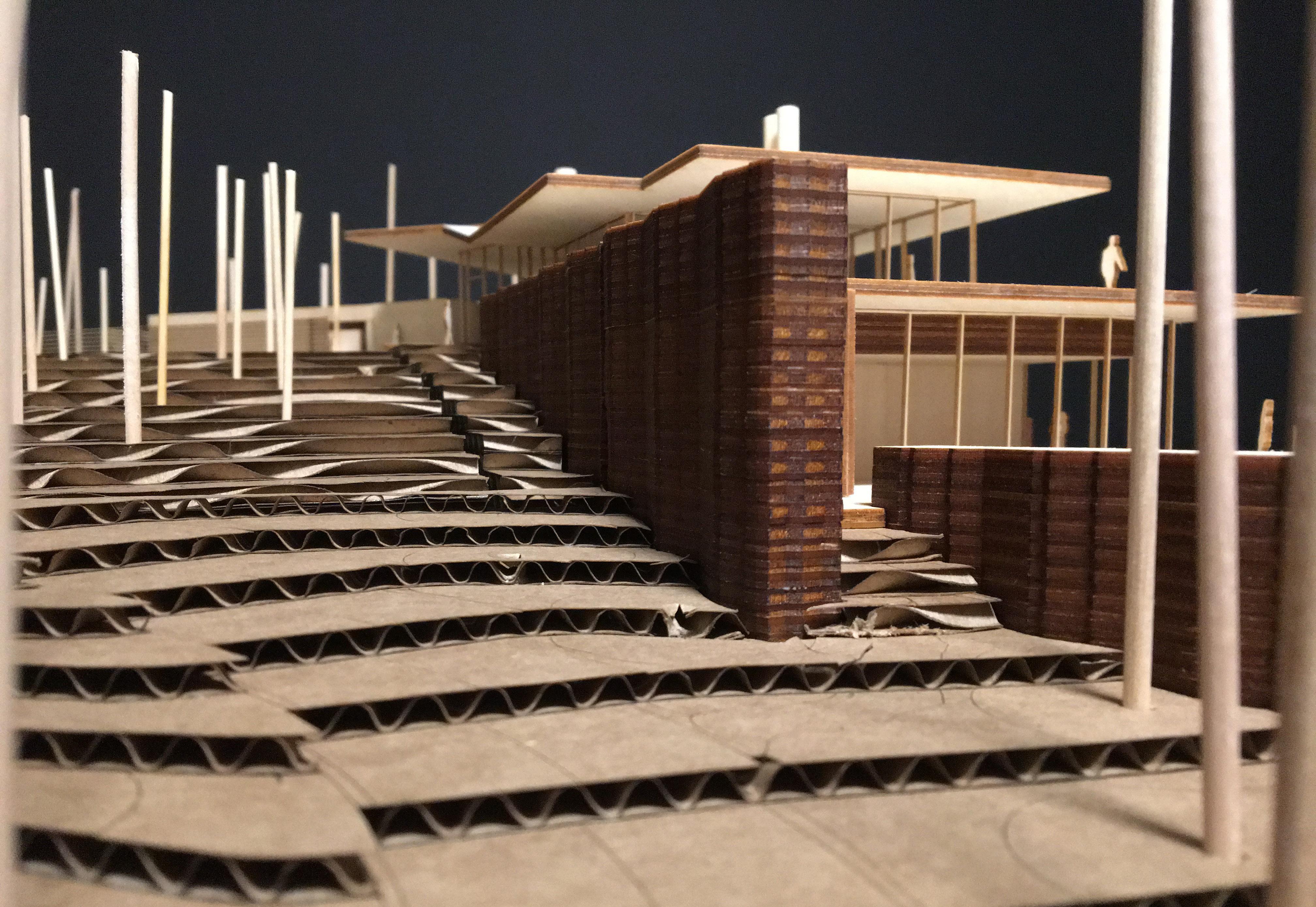
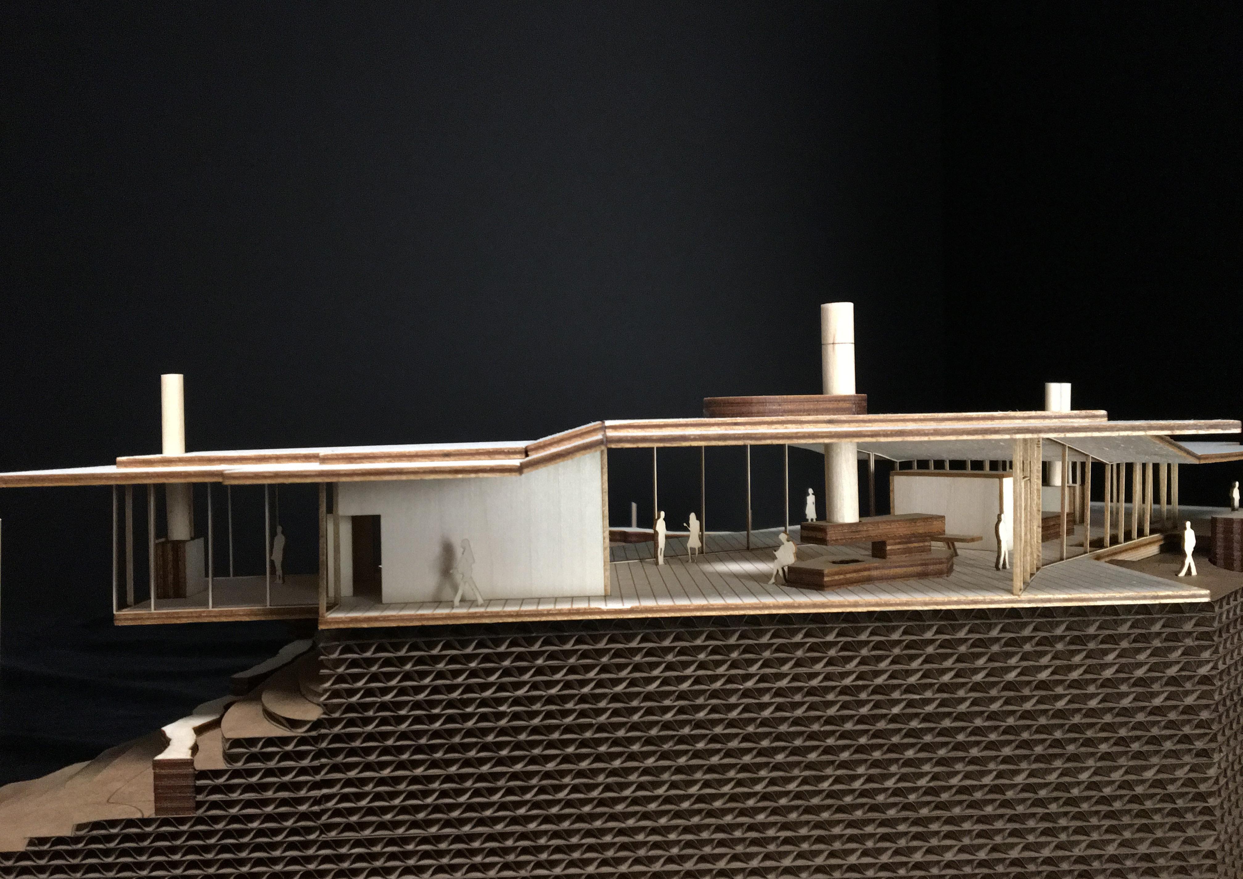
MODEL PLANNING Nestled on a hillside overlooking titicus reservoir, this house stretches out to embrace the scenic views. the owners desired an enticing vacation home that would take advantage of all that nature had to offer, while providing them with enough space to entertain friends and family. The design process included quickly reiterating physical models with the help of rhino modeling and the laser cutting. the large-scale model measured 36x48” and had to be split up into four pieces.
Model Looking West
MODEL PLANNING Nestled on a hillside overlooking titicus reservoir, this house stretches out to embrace the scenic views. the owners desired an enticing vacation home that would take advantage of all that nature had to offer, while providing them with enough space to entertain friends and family. The design process included quickly reiterating physical models with the help of rhino modeling and the laser cutting. the large-scale model measured 36x48” and had to be split up into four pieces.
Model Looking West from Driveway
Sectional Model showing Great Room and Master Bedroom