Single Drum Roller Service Manual
DOWNLOAD LINK
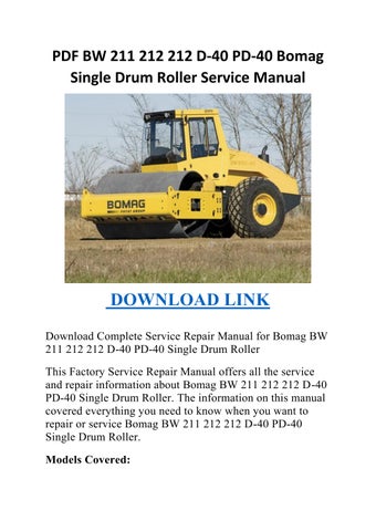
Download Complete Service Repair Manual for Bomag BW 211 212 212 D-40 PD-40 Single Drum Roller
This Factory Service Repair Manual offers all the service and repair information about Bomag BW 211 212 212 D-40 PD-40 Single Drum Roller. The information on this manual covered everything you need to know when you want to repair or service Bomag BW 211 212 212 D-40 PD-40 Single Drum Roller.
Models Covered:
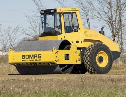
Bomag BW 211 212 212 D-40 Single Drum Roller
Bomag BW 211 212 212 PD-40 Single Drum Roller
Manual Contents:
General 7
1.1 Introduction 8
1.2 Safety regulations 9
1.3 General repair instructions 14
1.4 Tightening torques 24 Maintenance 29
2.1 General notes on maintenance 30
2.2 Table of fuels and lubricants 32
2.3 Running-in instructions 33
2.4 Maintenance chart 34 Technical data 37
3.1 Technical data 38 Connection overview 47
4.1 Connection overview 48 Tests and adjustments 51
5.1 Special tools, tests and adjustments 52
5.2 Checking the rotation speeds 56
5.3 Checking / adjusting the neutral positions of the travel pump 58
5.4 Pressure tests in the travel circuit 60
5.5 Checking / adjusting the vibrator shaft speeds 62
5.6 Pressure measurements in the vibration circuit 63
5.7 Check the leakage rate of the vibration motor 64
5.8 Pressure test in steering circuit 65 Flushing and bleeding 67
6.1 Special tools for flushing 68
6.2 Flushing – general 73
6.3 Flushing schematic travel circuit (distribution travel pump) 75
6.4 Flushing the travel circuit (travel pump distribution) 77
6.5 Flushing schematic travel circuit (distribution axle motor) 83
6.6 Flushing the travel circuit (axle motor distribution) 88
6.7 Flushing schematic for vibration drive 93
6.8 Flushing the vibration circuit 94
6.9 Bleeding the travel circuit 98
6.10 Bleeding the vibration circuit 100 Fundamental electrics 103
7.1 Understanding circuit diagrams 104
7.2 Terminal designations 109
7.3 Current and voltage 113
7.4 CAN-Bus 116
7.5 Resistance 118
7.6 Series / parallel connection 120
7.7 Ohm’s law 122
7.8 Electrical energy 122
7.9 Formula diagram 123
7.10 Metrology 124
7.11 Diodes, relays, fuses 127
7.12 Batteries 130
7.13 Three-phase generator 133
7.14 Electric starter 141
7.15 Telemecanique switch 144
7.16 Inductive proximity switches 147
7.17 Angle sensors 148
7.18 Plug connectors 150
7.19 Deutsch plug, series DT and DTM 150
7.20 Plugs and terminals in spring clamping technology 157
7.21 Electric modules 160 Special tools, electrics 161
8.1 Special tools, electrics 162 Electronic modules 171
9.1 BEM, BOMAG Evib-meter 173
9.2 Electric module K04 234
9.3 Heating/air conditioning control 238 Speedometer Module 245
10.1 Speedometer module 246 Service Training 249
11.1 Service Training 251 Engine 315
12.1 Diesel engine, general 316
12.2 Service side 317
12.3 Starter side 318
12.4 Lubrication oil circuit 319
12.5 Oil pressure switch and low oil pressure circuitry 321
12.6 Check the engine oil level 322
12.7 Changing engine oil and oil filter cartridges 323
12.8 Coolant circuit 325
12.9 Coolant temperature switch 327
12.10 Disassembling and assembling the coolant temperature switch 328
12.11 Replacing the thermostat 329
12.12 Checking the thermostat in disassembled state 330
12.13 Check the coolant level 331
12.14 Change the coolant 331
12.15 Checking the anti-freeze concentration 332
12.16 Clean the cooling fins on engine and hydraulic oil cooler 333
12.17 Three-phase generator 334
12.18 Fuel supply 336
12.19 Injection system 339
12.20 Injection pump replacement during service 340
12.21 Injection valve replacement during service 349
12.22 Checking / repairing injection valves 352
12.23 Fuel filter 357
12.24 Check, clean the water separator 359
12.25 Change the fuel pre-filter cartridge 359
12.26 Change the fuel filter cartridge 361
12.27 Checking the compression 361
12.28 Check, adjust the valve clearance 362
12.29 Boost fuel solenoid valve 364
12.30 Engine shut-down solenoid 365
12.31 Air filter 366
12.32 Cleaning, changing the dry air filter cartridge 367
12.33 Heating flange on engine 369
12.34 Checking the heating flange control 372
12.35 Electric throttle control 373
12.36 Engine monitoring 375
12.37 Engine 378
12.38 Special tools, Deutz engine (BFM 2012) 380 Air conditioning system 393
13.1 Physical basics 394
13.2 Refrigerant R134a 397
13.3 Compressor oil / refrigeration oil 398
13.4 Working principle of the air conditioning system 399
13.5 Monitoring devices 399
13.6 Description of components 400
13.7 Checking the compressor oil level 406
13.8 Checking the magnetic clutch 407
13.9 Inspection and maintenance work 408
13.10 Checking, replacing the refrigerant compressor V-belt 408
13.11 Service the air conditioning 409
13.12 Drying and evacuation 412
13.13 Emptying in case of repair 412
13.14 Leak test 413
13.15 Filling instructions 414
13.16 Trouble shooting in refrigerant circuit, basic principles 417
13.17 Trouble shooting, refrigerant circuit diagram 421
13.18 Trouble shooting procedure 422
13.19 Steam table for R134a 432 Replacing the cab window panes 437
14.1 Assembly of window panes 438
14.2 Special tools 439
14.3 Auxiliary materials 440
14.4 Removing and installing the window pane 442 Drum 447
15.1 Special tools, drum, single drum rollers 448
15.2 Repair overview for drum 450
15.3 Removing and installing the drum 457
15.4 Repairing the drum 462
15.5 Disassembling and assembling the change-over weight 495
15.6 Changing the rubber buffers and adjusting the pretension 498 Oscillating articulated joint 501
16.1 Special tools, oscillating articulated joint (BW177 to BW 216) 502
16.2 Repair overview oscillating articulated joint 504
16.3 Removing and installing the oscillating articulated joint 508
16.4 Dismantling the oscillating articulated joint 510
16.5 Assembling the oscillating articulated joint 515 Suppliers documentation 525
17.1 Travel pump 527
17.2 Vibration pump 617
17.3 Drum drive 655
17.4 Vibration motor 705
17.5 Axle drive motor 729
17.6 Axle 811 Circuit diagrams 933
18.1 Hydraulic diagram 581 202 10 935
18.2 Hydraulic diagram 581 202 11 939
18.3 Wiring diagram 582 702 09 943
18.4 Wiring diagram 582 702 29 979
18.5 Wiring diagram 582 702 41 1013
This manual can be used by anyone from a first time owner/amateur to a professional technician.Even the most novice mechanic can also easily follow the step-by-step
guides which are made simple by the illustrations and drawings.Keep this manual handy and use it often.
Performing routine, preventive maintenance will save you time & money by helping to prevent premature failure and unnecessary repairs.
Language: English
Format: PDF
Platform: Windows Phone, Ipad and Mac
Delivery: Instant Download After Payment
Support : Equipmentrepairmanuals@gmail.com