ji jt I 1Z 1i t S 4 x 79 11 0 if Tii ijn ld n lo 1 tlii fl tJb I i I 1 Jl t J Ul P 11 11 l uJJr 1 b II f r 1 f fj 0 f 1 t Ii i 1 t t twit i f i tlit T gt A j ctl i li ik F a f 5 ot F 1i 1 1 i J Datsun 210 1979 Service Manual Full download: http://manualplace.com/download/datsun-210-1979-service-manual/ This is the cut pages sample. Download all 548 page(s) at: ManualPlace.com

tfi

DATSUN 210 SERVICE MANUAL Model 8310 Series T OfOUoW lTY INISSAN N OIlCOIIO NISSAN MOTOR CO LTD 17 1 Ginza 6Chome Chuoku Tokyo 104 Japan QUICK REFERENCE INDEX GENERAL INFORMATION GI ENGINE TUNE UP ET ENGINE MECHANICAL EM ENGINE LUBRICATION SYSTEM EL COOLING SYSTEM CO ENGI NE FUEL EF EMISSION CONTROL SYSTEM EC ENGINE ELECTRICAL SYSTEM EE ENGINE REMOVAL INSTALLATION ER CLUTCH CL lMr MANUAL TRANSMISSION MT AUTOMATIC TRANSMISSION AT H PROPELLER SHAFT OIFFERENTlAL CARRIER PO FRONT AXLE FRONT SUSPENSION FA REAR AXLE REAR SUSPENSION RA BRAKE SYSTEM BR WHEEL A NO TI RE WT 0 STEERING SYSTEM ST ENGINE CONTROL FUEL EXHAUST SYSTEMS FE BOOY BF BOOY ELECTRICAL SYSTEM BE AIR CONOITIONING AC
TJili service manual has been prepared for the purpose of assisting service personnel of authorized NISSAN DATSUN dealerS in providing effective service and maintenance ofthe 1979 DATSU

Since proper maintenance and service are absolutely essential in satisfying the DATSUN owners this manu31 should be kept in a handy place for ready reference and should be carefully studied t
This manual includes procedures for maintenance adjustments minor service operations removal and instaUation and for rli mblyand assembly of components
Some ofthese service opemtions require the of Special Tools especially designed for effective performance ofservice operations
The special tools are presented at the end ofeach section
As you read through the llIintenance procedures inthis service m3 lual y lu w ll occasionally come across paragraphs headed NOTE CAUTION or WARNING A NOTE is supplemental information that is important to a particular procedure CAUTION and WARNING warn of steps that must be fonowed to prevent damage to some part ofthe car and or personal injury
The Quick Reference Index on the first page enables the user to quickly locate the desired section At the beginning of each individual section is a table ofcontents which gives the page mimber on which each major subject begins
An information illustrations and specifications contained in this manual are based on the latest product information available at the time of publication approval If your DATSUN model differs from the specificationS contained in this manual consult your NISSAN DATSUN dealer for information
Rights for alteration at any time ofspecifications and methods are reserved
liability for any personal injury or property damage occasioned by the use of this service manual in effecting maintenance or repair ofY 1 r DATSUN is in no way assumed by Nissan Motor Co td
Accordingly anyone using a service procedure or tool which is not specifically recommended by NISSAN must first completely satisfy himself that neither his safety nor the cars safety will be jeopaiiliiedby the service method selected
FO REWO RD
@ 1978 N1SSAN MOTOR
LTD Printed in
Not to be reproduced in whole orin part without the
of
NISSAN MOTOR Co lTD 17 1 G11ZlI6 chomo chuD kil TokyO l04 J n
CO
Japan
prior writtenpermisUon
Nissan Motor Company Ltd Tokyo Japan
DATSUN 210 Model 8310 Series SECTIONGI GENERAL INFORMATION CONTENTS MODEL VARIATION IDENTIFICATION NUMBERS CAR IDENTIFICATION PLATE CAR SERIAL NUMBER IDENTIFICATION NUMBER PLATE ENGINE SERIAL NUMBER COLOR CODE NUMBER LABEL M V S S CERTIFICATION LABEL EMISSION CONTROL INFORMATION LABE L MANUAL TRfNSMISSION NUMBER AUTOMATIC TRANSMISSION NUMBER APPROXIMATE REFILL CAPACITIES GI 2 GI 3 GI 3 GI 3 GI 4 GI 4 GI 4 GI 4 GI 4 GI 4 GI 4 GI 5 RECOMMENDED FuEL RECOMMENDED LUBRICANTS RECOf LUBRICANTS RECOMMENDED SAE VISCOSITY NUMBER LUBRICATION CHART MAINTENANCE SCHEDULE LIFTING POINTS AND TOWING PANTOGRAPH JACK GARAGE JA CK AND SAFETY STAND TOWING TIE DOWN SPECIAL TOOLS GI 5 GI 5 GI 5 GI 5 GI 6 Gillj9 GI9 GI eGI 9 p G I O
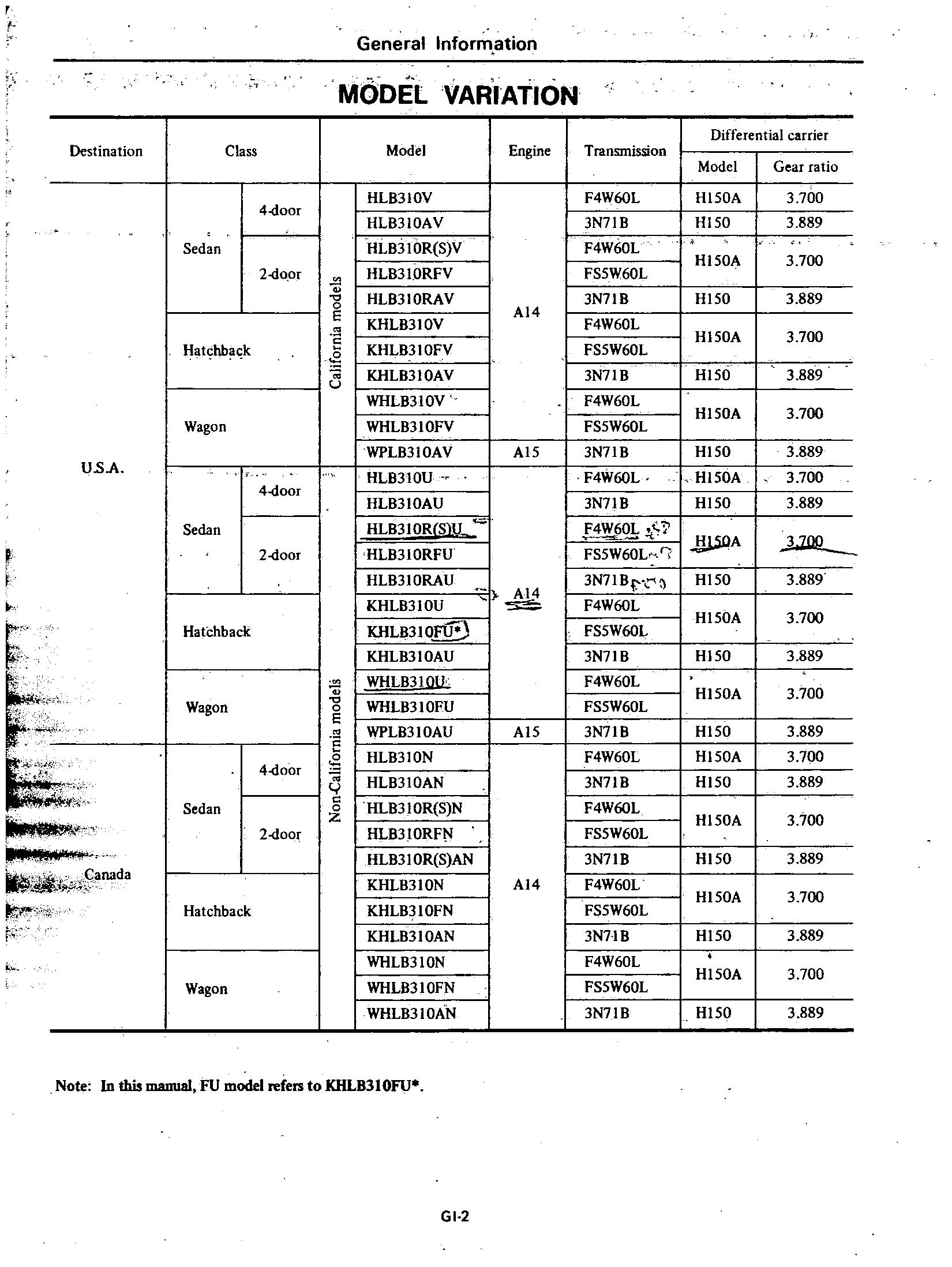
f Destination u sA t f l J Ifi i 1J ll d Canada C f Sedan Hatchba k Wagon Sedan HatChback Wagon Sedan Hatchback Wagon Class 4 door 2 do or I 4 door 2 door 4 door 2 door General Information MODEL VARIATION Model Engine I HL8310V I HLB310AV IHLB3IOR S V I HLB310RFV I i I HLB310RAV I KHLB310V I KHLB310FV J I KHLB310AV I WHLB310V I WHLB310FY WPLB310AV HLB310U I HLB310AU I HLB3IOR S lL IHLB310RFU I HLB310RAU AI4 I KHLB310U I KHLB310FU O I KHLB310AU I WHLB3 WU g WHLB310FU E WPLB310AU HLB310N HLB310AN c HLB310R S N HLB310RF I HLB3IOR S AN KHLB310N KHLB310FN KHLB310AN WHL83 ION WHLB310FN WHLB310AN Note In this manual FU model refers to KHLB310FU GI 2 I I I Transmission AI4
I
I
I
I
I
I
I
I
I
I
J I
I
I
I
I
I
AI5 AI5 AI4 Differential carrier Model Gear ratio Hl50A
HI50A
UOA
3 700 3
3 700 3
3
3
3
3
3
3
3
I 3
3
3
3
3
3
3
3
3
3
3
3
3
F4W60L
3N7lB
F4W60L
FS5W60L
3N71B I F4W60L J FS5W60L
3N71B
F4W60L FS5W60L 3N71B
F4W60L
3N71B
4 6Q
FS5W60L
3N7IBr
F4W60L I FS5W60L 3N71B F4W60L FS5W60L 3N7IB F4W60L 3N71B F4W60L FS5W60L 3N71B F4W60L FS5W60L
3N71B
F4W60L
FS5W60L
3N7lB
H150 Hl50A Hl50
H150 Hl50A Hl50 HI50A Hl50
Hl50 Hl50A HI50 HI50A HI50 HI50A HI50 H150A HI50 HI50A Hl50 Hl50A Hl50
889
889
700
889
700
889
700
889
700
889
700
889
700
889
700
889
700
889
700
889
700
889

The meaning of prefix and suffix 0 Sedan K Hatchback W Wagon @ A 14 engine p A 15 engine iD Left hand drive Note 0means no indication General Information lL I OR K H L B310 R S DlA F v California models Non California models for U A Non California models for Canada 4 speed Manual transmission 5 speed Manual transmission Automatic transmission L 0 Deluxe model S Standard model 0 4 door L@ 2 door CAR IDENTIFICATION PLATE The car identification plate is lo cated on the cowl top in the engine compartment v r LCQ23 Fig Gl l Car Identification Plate Location GI 3 IDENTIFICATION NUMBERS L v G N @J F A CAR SERIAl NUMBER HL I A rp The unit and car numbers are stamped and registered at the factory The engine and vehicle identifica tion numbers are used on legal dacu ments These numbers are used for factory communications such as Techn cal Reports Warranty Claims Service Journals and other informa tiOD LC025 Fig GI 2 CarSerial Number Location

r
NUMBER PLATE The identification number plate is located on the upper surface of the instrument panel and can be seen from outside through the windshield glass The identification number consists of the car model and the serial number LC024 Fig GI 3 Identification Number Plate JAJcation ENGINE SERIAL NUMBER The engine serial number is stamped on the right hand side of the cylinder block The number is broken down as shown in the following chart according tothe engine Engine model Engine number AI4 AIS AI4 XXXXXX AIS XXXXXX J lL @ 1 C SP062 Fig C1 4 Engine Serial Numbf Location General Information COLOR CODt NUMBER LABEL The body color code number label is attached to the top face of the radiator core support GI391 Fig GI 5 Color Code Number Label Location M V 5 S CERTIFICATION LABEL The M V S S certification label is attached to the driver s sidelock pillar or center pillar as shown in Fig GI 6 s p LC026 Fig GI 6 M V S S Certification Label Location GI 4 EMISSION CONTROL INFORMATION LABEL The emission control information label is attached to the back of the engine hood on the right side MANUAL TRANSMISSION NUMBER The transmission rial number is stamped on the front upper face of the transmission case GI225 Fig GI B Manual Transmission Number Loc on AUTOMATIC TRANSMISSION NUMBER The transmission serial number plate is attached to the right hand side of the transmission case AT344 Fig Gl 9 Automatic Transmission Number Location
IDENYiFICAYiON

Erigine crankcase EIgine cooling system Transmission case Final drive case housing Steeringgear box Fuel tank Air conditioning system Refrigerant Compressor oil f tl It J 4i 1 protect the catalytic copverter froitr contamination General Information APPROXIMATE REFILL CAPACITIES Without oil filter AI4 Al5 w Al5 M T AfT MiL A T Liter US measure 3 2 3 qt 2 8 3 qt 3 7 llLgt 33 3 qt 5 2 5 qt 5 0 5Y qt 5 9 6 Y at 57 6qt 1 3 2 Y ot 1 2 pt 53 5 qt 0 9 1 pt 0 25 pt 50 13Y I 0 8 tol Okg 18 to 2 2 1b 0 237 8 0 floz Withoil Without heater With heatfr MaDllal soeed 5 spee Automatic 1 1 Includes 2 7 liters 2 US qt 2 Imp qt for torque converter RECOMMENDED FUEL Use an unleaded or low lead gaso line with a minimum octane rating of 91 RON Research Octane Number For cars equipp d with the Cataly tic converter California and FU mod els use only unleaded gasoline to RECOMMENDED Lubricant GasOline engine oil Gear oil Transmission and steering Differential Au omatic TIM fluid Multi purpose grease Brake and clutch fluid Anti freeze L NDED LUBRICAN COMMENDED iI VISCOSITY NUMBER t1 NGON 0 L J I j H IlL t l lc30 ItM 7 l U ItM I L L tJ 30 I I fu JIl inld do o II LliOwl 10 I t I I j r I I J 1 21 1 71 c DIUt I2lItMOl UGIIII FI R NIl01 a Specifications Remarks APISE API GL4 Further details refer to recommended SAE viscosity chart API GL 5 Type DEXRON NLGI No 2 Lithium soap base DOT US FMVSS No 116 Ethylene glycol base GI 5 Imp meas4re 2 qt 2 qt 3Y qt 2 it 4 qt 4 q 5Y qt 5 qt 2Y pt 2 pt 4 qt I pt pt II gal 18 to 2 2 lb 83f1 oz Ji j
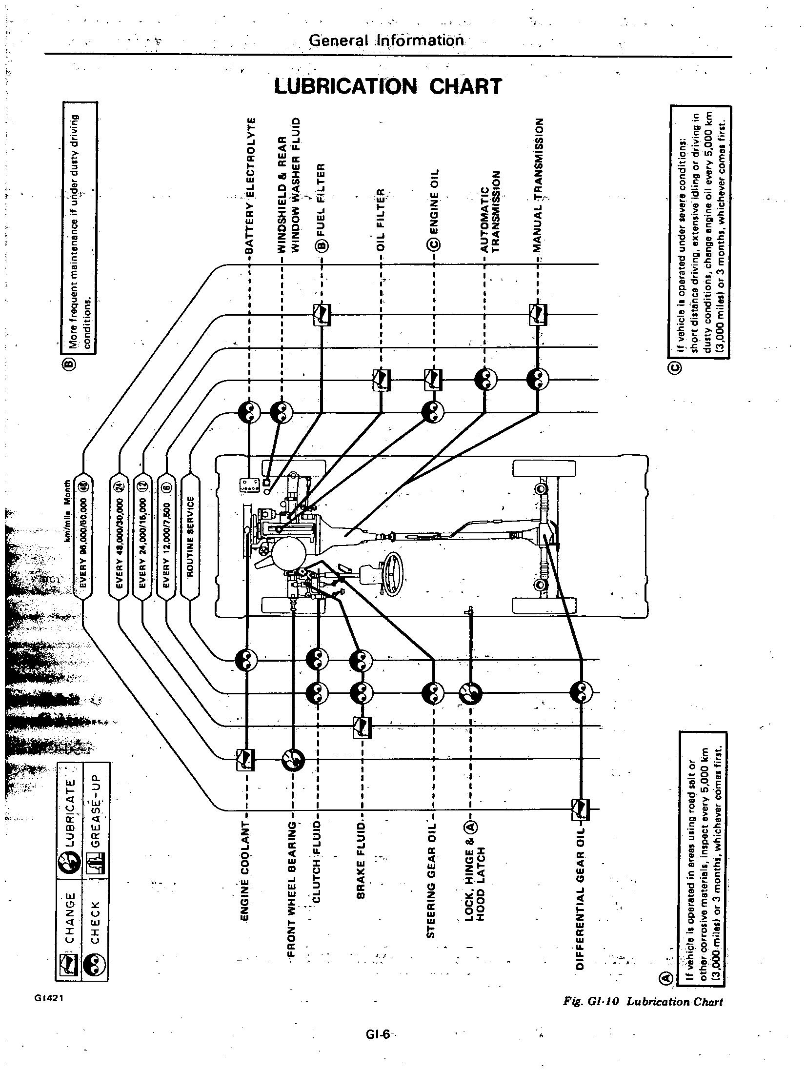
Ci r zs C itlNGE C iEel @ Nlo e uenteintoneneeit u de dU W do n condit oot If s WIoli 1I ooo I IBR eAiE QGGREtlSI IP v 0130 u v 1 000 000 @ B iiERU E ECTROuTE VlltlOSl lIE O RE R WINOOW Vl SIIER fl UIO @fUEl fII TER ENGINE cool tl fRON WIIEEI BE l RIN CI U CIl f I IO l Ol fll ER Cb BR llE UIO @EtlG NEO STEERING GE l R Ot OCll lIltlGE 8o@ 11000 l TCII tj l U OM l TIC TR tlsMISSIOtl 0 i q Gl Z3 0 a0 30 oI M NU l 1R l tlSNlISSIOtl OlffERENTI l GE l R Ol Q It ve cle ooe od unde vere cond on ho dillonee drivIng e ten ve Idling 0 d NIOg 0 dU W condillon chenge eog oe 0 e v 5 000 3 000 OT 3 ooth h C ve co e @ t 0 @ Q lif II vohicle ooeretod 0 eree ullng oed all or o her corro ve e e ie In 08c everY 5 000 3 e 1 or 3 on h hlChe co e Iofl

w w ID P u f 600 rlI 000 mile ser ce one 0 e lUe US d erfol1 ance and ol tirrlUlll engine con Itlon 1 Ip lEP CE OPEl P lI0 hId formed at numbef ot periodic roll tero OU k lllele Ie 0 onlhO h chOVe co e 1000 efS es Month 1 6 P 1EP CE lEI VPL 1 24 36 48 60 72 7 5 15 2 5 301 37 5 45 6 1 18 24 30 36 G l A should be ometert TIlles ot onth EMISSION CONll O MMN1ENJl NCE P P P P ota e 8t exhaust a NEt c ear1lf C P l l l l On belU 11 l I EnQltltl 0 11 0 filter engine COO Brot Coo n v te hO conne on P P P laC 1 lrn titt1ng hOleS 8l eof ect Ql1 P IdlG rpm ca elo dIe p M fl turu ra IO P P P ChO 0 h8 chOke pl ink 1 de th ca IV e conv NOf call QP 2 I h t olt v on dec 0 iF vel filter net hO p p nO eonn on tc 2 p cl ner It ca bU tO P ode h e ra V e conv rto V S P d caP cal O n 2 0 cI n tnte on C M n od rh c ralV e con t8 carburetor a and CB ff lodels P P p o e p control o n P f l I grtltlOfl tll1U Spal plIJQ l nltIOfl Iflng 2 po cr nkca ion P C v 8 1 Vtoti tlOll r10lCS e pol ln F nk c liel v iI SO pped l 1 Calilorn odO h ca V p nd c on e t on It J r a g q c Clll 5 o 3Qool

MAiNTENANCE OPERATION Periodic maintenance should be performed at number of kilometers mila or month whichewr comes first Kilometers 1 000 Mile 1 000 M 3nthl MAINTENANCE INTERVAL 1 6 12 24 36 48 60 72 111 117 611 11511122 511 30 1137 5 45 6 12 16 24 30 36 UNDERHOOD MAINTENANCE Gl The above charts show the normal maintenance schedule Dependir tg upon weather andatmospheric conditions varying road surfaces individual driving habits and vehicle usage additionai or more frequen maintenance may be required Abbreviations A Adjust R Replace Inspe t correct replace if necessary L Lubricate NOTE 1 If vehicle operated under evere conditions hort distance driving extensive idling or driving in du ty condition change angine oil every 5 000 km 3 000 mile or 3 month whlchevar come first 2 More frequent maintenance if under dusty driving condition 3 Replace differential gear oile ery 96 000 km 60 000 mila or 4 years whichaver com first 4 If vehicle operated in ereas u ing road alt or other corro ive material inspect evary 5 000 km 3 000 mile or 3 months whichever comes first
FRONT SIDE
PANTOGRAPH

REAR SIDE
FRONT SIDE
General Information
LIFTING POINTS AND TOWING
GIOB5 Fig GI II Wheel
Apply
WARNING a
Always
b
Jack up TROSO Fig GI 12 Jack Up Points GARAGE JACK AND SAFETY STAND
When
JACK Place wheel chocks at both front and back of the wheel diagonally opposite the jack position
Chocks
the pantograph jack fur nished with the car to the position indicated below in a safe manner See Fig GI 12
Never get under the car while it is supported only by the jack
use safety stands to support frame when you have to get under the car
Block the wheels diagonally with wheel chocks
WARNING
carrying out operations with the garage jack be sure to support the car with safety stands
I
2
GI372 Fig GI 13
3
GI373 Fig GI 14 Front Supportable
4
When jacking up the front of the car place the chocks behind the rear wheels to hold them
Apply the garage jack under the front suspension member Be sure not to lift up the engine oil pan
Front Jack Up Point
Jack up the car gently just high enough to place the safety stands under both the side members Place the stands at the position indicated in Fig GI 14
Point
Release the jack slowly
2
1 1 Il GI378 Fig GI 15 Rear Jack Up Point GI 9 3 Jack
car
Place
GI379 Fig GI 16 Rear Supportable Point Rear axle c rue GI392 Fig 01 17 Rear Supportable Point Body
a It is necemry to use proper towing equipment to
car during
towing operation Towing is
dealer
b All applicable
laws and
regarding
operation must
When jacking up the rear of the car place the chocks at the front side ofthe front wheels to hold them
Apply the garage jack under the differential carrier
up the
gently just high enough to place the safety stands under the rear axle case or body
the stands at the positions indicated below
TOWING CAUTION
avoid possible dam age to the
a
in accordance with Tow ing Procedure Manual at
side
State or Provincial in Canada
local laws
the towiilg
be obeyed
Front
towing hooks are provided on both front side members
GI417
Fig GI 15 Front Towing Hook
REAR SIDE
Rear towing hooks are provided on botrear sides GI418
Fig GI 16 Rear Towing Hooks
CAUTION
a Before towing make sure that the transmission axles steering system and p r train are in good order
If any unit is damaged a dolly must be used
If the transmission is inoperative tow the car with the rear wheels off the ground or with the propeller shaft removed

c When the car is towed with its front wheels on the ground secure the steering wheel in a straight ahead position with the ignition key turnedin OFF position
d When towing an automatic trans mission model on its rear wheels do not exceed 30 km h 20 MPH and a distance of30 km 20 miles
e Release the parking brake and set the gearshift lever in Neutral position before starting to tow the car
REAR SIDE
Use rear towing hooks for tie down at the rear side
Special Tools play very important rolein the maintenance of cars These are essential to the safe accurate and speedy servicing
The working times listed in the column under FLAT RATE TIME in FLAT RATE SCHEDULE are com puted based on the use of Special Tools
TIE DOWN
FRONT 51 DE
Use front towing hooks for tie down at the front side
General Information
SPECIAL TOOLS The identification code of ffi linte nance tools
is made up of 2 alphabeti calletters and 8 digital figures
STOOOOOOOO KVOOOOOOOO Special Tool Special Tool GI l0
The heading two letters roughly classify tools c equipment as
EMOOOOOOOO GGOOOOOOOO lMOOOOOOOO HTOOOOOOOO Engine Overhauling Machine General Gauge Garage Tool Hand Tool
210
Special Tool
information
Tools
Refer to Service Bulletin DATSUN
fOJ
List and further
of Special

DATSUN 210 Model 8310 Series SECTIONET ET ENGINE TUNE UP CONTENTS EMISSION CONTROL DEVICES BASIC MECHANICAL SYSTEM ADJUSTING INTAKE AND EXHAUST VALVE CLEARANCE CHECKING AND ADJUSTING DRIVE BELTS CHANGING ENGINE OIL REPLACING 01 L FI LTER CHANGING ENGINE COOLANT CHECKING COOLING SYSTEM HOSES AND CONNECTIONS CHECKING ENGINE COMPRESSION IGNITION AND FUEL SYSTEM CHECKING BATTERY CHECKING AND ADJUSTING IGNITION TIMING CHECKING IGNITION WIRING CHECKING AND REPLACING SPARK PLUGS CHECKING AND ADJUSTING CARBURETOR IDLE RPM AND MIXTURE RATIO CHECKING CHOKE MECHANISM Choke plate and linkage CHECKING FUEL SHUT OFF SYSTEM FU models ET 2 ET 3 ET 3 ET 3 ET 3 ET 3 ET 4 ET 4 ET 4 ET 5 ET 5 ET 5 ET 6 ET 6 ET 7 ET 9 ET 9 REPLACING
ET
CHECKING
EMISSION CONTROL SYSTEM ET 11 CHECKING
ET 11 REPLACING
E 1122i REPLACING
E C REPLACING
ETf CHECKING
E1P12 CHECKING VAPOR LINES Eli J2 CHECKING
I f III VALVE ET 13 REPLACING CARBON CANISTER W FILTER ET d SERVICE DATA AND SPECIFICATIONS ET 14 TROUBLE DIAGNOSES AND CORRECTIONS ET 16 SPECIAL SERVICE TOOL ET 23
FUEL FILTER
10
FUEL LINES Hoses piping connections etc ET 10 REPLACING AIR CLEANER FILTER ETlO CHECKING AUTOMATIC TEMPERATURE CONTROL AIR CLEANER ET 10
VACUUM FITTING HOSES AND CONNECTIONS
AIR PUMP AIR CLEANER FILTER Except FU models and Canada models
AIR INDUCTION VALVE FILTER FU models and Canada models
PCV VALVE AND FILTER
VENTI LATION HOSES
FUEL TANK VACUUM RELIEF

EMISSION CONTROL DEVICES En ine model AI4 A1S B310 NonCaliCor Non California models Califor nia Car model California models Ecept for C nada Canada nia modeb models Exceptfor Canada M T M T A T Ti ansmiuion M T A T Except A T FU M T A T Station Wagon FUmodels models models AIR CLEAN A T C air cleaner X X X X X X X X X ER Idle compensator Dual type X X X X X X X X X Fresh air duct X X X X X X X ENGINE Early fuel evaporative system X X X xl X X X X X BASE Exhaust gas type CARBV P T C auto choke X X X X X X X X X m RETOR l Thrttle opener X X X X X X X X Q Fuel shut off system X 3 m ll i Dash po X X X X X X X X X N l IGNITION H I C ignitor X X X X X X X X X c SYSTEM Spark timing contra system T e S X X X l X X X ll Thermal vacuum valve X X X X X X c Vacuum delay valve X X X 0 X A I S Air pump Air pump air cleaner check valve X X X X x X A B valve Combined air control C A C valve X X X Relief valve X X X Air induction valve Filter A B valve X X X E G R Exhaust gas recirculation E G R valve X X X X X X X X X SYSTEM Thetmalvacuum valve X X X X X X X X X Back pressure transducer B P T valve X X X X X X X CATALYZER CatalytJc converter X X X X Newly equipped unit on 1979 models M T Manual transmission Remarks X Available A T Automatic transmission Not available A T C Aute matic tempeJature control P T C POlitive temperature coefficient A I S Air injection system or Air induction system A B valve Anti backfire valve

Engine Tune up BASIC MECHANICAL SYSTEM
INTAKE AND EXHAUST VAL CLEARANCE Note After tightening cYlinder head bolts adjust intake and exhaust valve clearances Valve clearance ai ljustment cannot be made while the engine is in opera tion To adjust proceed as follows I Start engine and warm it up uritil water temperature indicator points to the middle of gauge Then stop engine 2 Rotate crankshaft to bring No I cylinder in top dead center on its compression stroke 3 Remove valve rocker cover Adjust valve clearance at following four points while engine is still hot CD Exhaust valve of No I cylinder @ Intake valve of No I cylinder @ Intake valve of No 2 cylinder @ Exhaust valve of No 3 cylinder Note Numbers in circle agree with those in accompanying sketch tiri Fig ET 1 Adjusting Value Clearanu 4 Again rotate crankshaft one turn so that No 4 piston is in top dead center on its ompression stroke Ad just following valves CID Exhaust valve of No 2 cylinder @ Intake valve of No 3 cylinder j Intake valve of No 4 cylinder @ Exhaust valve of No 4 cylinder Adjustment should be made while engine is hot After all valves have been adjusted correctly tighten lock nut firmly to secure ihe adjustment Valve clearance Hot Intake 0 35 mm 0 014 inl Exhaust 0 35 mm 0 014 in tJl Tightening torque Valve rocker adjusting nut 1 6 to 2 2 kltm 12 to 16 ft lb Alternator Crankshaft pulley Unit mm in Idler pulley Fig ET 2 CHANGING ENGINE OIL 1 Check if oil is diluted with water or gasoline Drain and refill oil if necessary Note a A milky oil iiulicates the presence of cooling water Isolate the cause and take corrective measure b An oil with extremely lowviscosity indicates dilution with gasoline 2 Check oil level If below the specified level raise it up to the H level 3 Change engine oil in accordance with the maintenance schedule Engine oil capacity A14 With oil filter 3 7 liters 3 U US qt 3 Yo Imp qtl ET3 CHECKING AND ADJUSTING DRIVE BELTS I Check for cracks or damage Re place if necessary 2 Normal drive belt deflection is showndI figure below when moderate thumb pressure is applied midway between pulleys Thumb pressure 10 kg 221bl Idler pulley Compressor p1 AC710 Checking Drive Belts for Deflection Without oil filter 3 2 liters 3 USqt 2 U ImP ltl A15 With oil filter 3 3 liters 3 US qt 2 U Imp qd Withoutoil filter 2 8 liters 3 us qt 2 Imp qd REPLACING OIL FILTER The oil filter is a cartridge type and can be removed using Oil Filter Wrench STl9320000 I Check for oil leaks past gasketed Oange If leakage is found retighten just enough to stop leakage If reo tightening is no longer effective re
ADJUSTING
pl ice mter as an assembly
2 When installing oil mter tighten by hand
Note Do not overtighten oil filter lest leakage shoUld occur
CHANGING
PERMANENT ANTI FREEZE COOLANT
Note The permanent anti freeze coolant is an ethylene glya lbase product containing chemical in hibitors to protect the cooling system from rusting and corrosion The anti freeze does not cOntain any glycerine or ethyl alcohol It will not evaporate or boil a ay and can be ilsed with either high or low temperature thermostats It flows freely transfers heat efficiently and will not clog the passages in the cooling system The anti freeze must not be mixed with other product This coolant can be used throughout the seasons of the year Whenever coolant is changed the cooling system must be flushed and refilled with a new coolant Check the coolant level See instructions attached to the anti freeze container for mixing ratio ofanti freeze to water

ENGINE COOLANT
CHECKING COOLING SYSTEM HOSES AND CONNECTIONS Check hoses and fittings for loose connections or deterioration Re tighten or replace ifnecessary
OF RADIATOR CAP Apply
to
I jngine Tune up ET012 Fig ET 3 Testing Radiator Cap COOLING SYSTEM PRESSURE TEST Witli radiator cap removed apply reference pressure 16 kgfcm2 23 psi to the cooling system by means 0 no Fig ET 4 Water capacity M Tmodelsl Without heater 5 2 liten 5 1f US qt 4 Imp qt With heeter 5 9 Iiten 6 US qt 5 Y Imp qt Watercapacity AfT modelsl Without heater 5 0 liters 5 y US qt 4 Imp qt With heater 5 7 liten 6 US qt 5 Imp ill CHECKING ENGINE COMPRESSION Note a To check cylinder compression it is essential to remove all spark plugs The purpose of this test is to ET 4
exces
M
b
c
I Warm
2
3
4
FiI ET S ET529 Testing Compre
Pr
5 Depress accelenit6r pedal to open throttle and choke valves Note Do not pump pedal 6 Start engine as quickly as pos sible Compression pressllre kgcm2 ii at rpm Standard 13 5 192 350 Minimum 12 5 1781 350 If cylinder compression
e or more cylinders is low pour
quantity of engine oil
and
compression I If
INSPECTION
reference pressure 0 9 kgjcm2 13 psi
radiator cap by means of a cap tester to see if it is satisfactory Replace cap assembly if necessary
determine whether there is
sive leakage past piston rings head gasket etc To test engine should be heated to the operating t
ture and throttle valve opened
Cylinder compre on in Cylinders should not be less than llO of the highest reading Different compres sion in two ore more cYlinder usual ly indicates an improperly seated valve or broken piston ring
Low compression in cylinders am result from worn piston rings This trouble may usuaDy be accom panied by ex ssive fuel consump tion
up engine sufficiently
Disconnect aU spark plugs
Disconnect anti dieseling solenoid valve connector
Properly attach a compression tester to spark plug hole in cylinder being tested
sion
s8ure
in o
a small
into cylinders through the spark plug holes
retest
addingoil helps the compres
IGNITION AND FUEL SYSTEM CHECKING

sion pressure chances are that piston rings are worn or damaged 2 If pressure stays low the likeli hood is that valve is sticking or seating Engine Tune up improperly 3 If cylinder compression in any two adjacent cylinders is low and if adding oil does not help the compres sion there is leakage past the gasketed surface Oil and water in combustion cham bers can result from this problem
BATTERY
six vent plugs and
electrolyte level
If
pour
Overflow Correct Shortage t t j t t t EE358 Fig ET 6 Checking Electrolyte Level 2 Measure the specific gravity of battery electrolyte E T372 Fig ET 7 Checking Specific Gravity of Battery Electrolyte Over
Full charge value at 200C 680F 1 1 26 Permissible value
CHECKING AND ADJUSTING IGNITION TIMING
spark plugs for condition 2 Thoroughly
3
4
5
Idling speed Manual transmission 700 pm Automatic transmission 6S0 rpm in
position ET S
Ignition
Manual transmission SO
California
100
Non
models Automatic
SO
California
I Remove
check
in each battery cell
necessary
distilled water
1 22
Frigid climates Other climates Note a Clean top of battery and terminals with a solution of baking soda and water Rinse off and dry with com pressed air Top of battery must be c1 n to prevent current leakage between terminals and from posi tive terminal to hold clamp b In addition to current leakage prolonged accumulation of acid and dirt on top of hattery may cause blistering of the material covering ronnector straps and rorrosion of straps c After tightening terminals coat them with petrolatum vaseline to protect them from corrosion CAUTION If the battery cables are disconnected they should be tightly clamped to the battery terminals to secure a good contact Over I 20
Check
remove dirt and dust from crank pulley at timing mark location and front cover at timing indicator
Warm up engine sufficiently
Connect engine tachometer and timing light in their proper positions
Adjust idling speed to the specifi ed value
0
WARNING When selector lever is shifted to 0 position apply parking brake and block both front and rear wheels with chocks Note a On FU models set idling speed with distributor vacuum hose dis connected b Disconnect distributor vacuum hose at distributor diaphragm side and plug hose with blind plug See Fig ET ET501 Fig ET B Disconnecting Distributor Vacuum Hose 6 Check ignition timing with a timing light to ensure that it is adjust ed to specifications indicated below
timing
B T 0 C rpm
FU models
B T 0 C pm
Canada
transmission
B T 0 C rpm
models

SO B T D C rpm Non California models except Canada 100 B T D C 650 rpm Canada models Note On FU models ignition timing is set
a condition where distributor vacuum
If necessary adjust ignition timing as follows I Loosen set screw
dis
cuJ be
hand 2 Adjust ignition
3 Lock distributor set screw and make
YJ Fig T 9 Adjusting Ignition Timing 7 On FU models proceed as fol lows I Remove blind plug
dis
vacuum
distributor
2 If
CHECKING IGNITION WIRING Use an ohmmeter to check resist ance on high tension cables 1 Disconnect cables
spark plugs and remove distributor together with high tension cables Note Do not remove cables from cap Engine Tune up 2 Connect the ohmmeter between cable terminal on the spark plug side and the corresponding electrode inside cap 3 If the resistance is
30
ohms remove cable
cap and
the cable
only If resistance is
replace
assembly Fig ET IO Checking High Tension Cable u sA models Type FU models Standard Hot type Cold type U S Amodels Canada models r 1g mm in FU models Canada models Tightening torque kg m ftlb ET 6 Stan rd Hot type Cold type S aridard Hot type Cold type CHECKING AND REPLACING SPARK PLUGS I Remove and clean plugs in a sand blast cleaner Inspect each spark plug Make sure that they are of the specifi ed heat range 2 Inspect insulator for cracks or chips Check both center and ground electrodes 3 If they are excessively worn re place with new spark plugs 4 Replace spark plugs in accordance with the maintenance schedule BP ES ll L46PW l BP4E ll L47PW ll BP7ES ll BP6ES ll L44PW II L4 PW 11 BP5 EQ 13 L46PM 13 BP4EQ 13 L47PM 13 BP6EQ 13 L45PM 13 BP7EQ 13 L44PM 13 BPR5ES BPR4ES BPR6ES 1 0 to 1 LQ39 to 0 043 l to 1 0 043 to 0 051 0 8 to 0 9 0 031 to 0 035 15 to i6 P to 14 Datsun 210 1979 Service Manual Full download: http://manualplace.com/download/datsun-210-1979-service-manual/ This is the cut pages sample. Download all 548 page(s) at: ManualPlace.com
under
hose is discon nected
until
tributor
moved by
timing to speci fications
sure that timing is correct
from
tributor
hose and connect hose to
diaphragm
engine speed varies in this state set idling speed at specified value with throttle adjusting screw
from
more than
000
from
check
resistance
still more than 30 000 ohms
c3ble
