
ARCH_portfolio
Joaquin Montes Texas Tech University College of Architecture Urban Design & Community Planning CertificateSelected Works
Architectural Portfolio: Joaquin Montes
Joaquin Montes
jomontes6@gmail.com 915.241.0356
TEXAS TECH UNIVERSITY
Master of Architecure
Texas Tech University College of Architecture Lubbock, Texas
Aug. 2015 – Expected May 2018
Bachelor of Science in Architecture
Texas Tech University College of Architecture Lubbock, Texas
Aug. 2011 – May 2015
EXPERIENCE
PhiloWilke Partnership
Architectural Associate/ Staff II
11275 S. Sam Houston Pkwy W, Suite 200 Houston, Texas 77031 (832) 554-1130
October 8, 2018 - Current
W Partnership, Inc.
Architectural Staff I 5120 Woodway Dr, Suite 8000 Houston, Texas 77056
July 3, 2018 - October 8, 2018
GRAPHIC SKILLS
ADOBE ACROBAT
ADOBE ILLUSTRATOR
ADOBE INDESIGN
ADOBE PHOTOSHOP
ARC GIS
AUTOCAD
BLUEBEAM
CLIMATE CONSULTANT
DPROFILER
ENDSCAPE
EXCEL
FREECOMMANDER
LASER CUTTING CAPABLE
MICROSOFT OFFICE
REVIT
RHINO, V-RAY
SKETCHUP
TWINMOTION
3D PRINTING
ABOUT ME
I am a hard working individual with a curiosity to learn and an open mind. I like to explore new and exciting topics from all over the world and see if I can integrate them in my design and artwork. My interests are broad, but I often focus on various types of art like, music, dancing, cooking, and design in all senses of the word. My current long time endeavor and hobbies are exercising, guitar, and oil painting.
i.
Studio Work
01_Place Du Caire
09_The Waller
Professional Experience
24_ HMCLH Medical Office Building
29_Multicare Health System Emergency Center
33_Hope Clinic Health and Wellness Center
39_HCC Challenger Learning Center
43_Personal Works
Table of Contents
ii.
Place Du Caire | Paris, Frace | Study Abroad | Prof. Dean Vernooy, Hal Sharp, and Dr. Clifton Ellis
The Place focuses on a neighborhood in transition, and establishes a redevelopment of public space to allow for new programmatic activities to occur. The Place contains cafes, the Institute de la Mode Contemporaire (Institue of textile fashion/ IMC), a Liturgical Space, and a Vitrine for textile production.
The Place allows for pedestrian traffic to circulate through different program types in between two main streets.
A fluid progression is implemented in the design through communal cafes, alleys, and the programmed structures to navigate users from a neighborhood/ private program type, to a retailcommercial space/ public program type.
Paris, France Map Paris Region Map Retail Historical Food/ Markets Main St. Main St. Neighboring St. Neighboring St. Park Park Commercial Site Site Site Diagram 01 Paris, France Map Paris Region Map Site PlanLo vr Site Jarden de uileries Conseil d’Etat Musee Grevin Louvre Site Notre Dame Arc De Triomphe Place De La Bastille Lycee Eugene Napoleon Ecole Boul e L’eglise de a Madeleine Cimetiere Pere-Lachaise Maire de Paris 20e arrondissement Hopital la Rochefoucaul Marie du 14eme Lycee Francois Villion Asile N.D de BonSecours Paroisse Notre Dame du Rosaire Cimetire du Montparnasse Luxembourg Gardens Jardin des Plantes Jarden des Tuileries Le Tombeau de Napolean Syndicat Stud Caisse Epargne Eiffel Tower Champ De Mars Place du Caire Derriere du Cai DerriereduCaire Rued’Aboukir Rued’Aboukir Rue du Caire Rue es Forges RueduNil Rue Dussouds RueSte.Foy Passage du Caire Passage du Caire PassageduCaire PassageduCaire Rue d’Alexandrie Retail Restaurant Hotel
DerriereduCaire
Passage du Caire PassageduCaire
Site Plan 02 -
Rue Poissonniere
RueduNil
Place Site Plan N
Rue Reaumur
Cafe 1st Level EX 01 EX 02obby o Desk l N u d e u R EX 01 EX 02obby l N u d e u R Apa tme 02 Apa tme 01 l N u d e u R 3rd Level N 10’ 2nd Level N 1st Level N 5’ Level 3 FF Level 2 FF Level 1 FF Vitrine Floor Plans 03
Vitrine Elevation_01
Vitrine Elevation_02
04
Vitrine Longitudinal Section_03
25’ 29’ Vitrine Elevation 01 N Vitrine Elevation 02 N Vitrine Longitudinal Section N Vitrine Transverse Section N 29’ Vitrine Elevation 01 N Vitrine Elevation 02 N 29’ Vitrine Longitudinal Section N Vitrine Transverse Section N
Vitrine Cross Section_04
10’ 5’ 0’ N
0’ 5’ 10’ N 3’ 0’ 10’ 25’ 29’ Longitudinal Section _Liturgical space | Front Facade Elevation_Vitrine | Front Facade_IMC Plan 05
Liturgical Space Plan
06 Liturgical Space Elevation Liturgical Space Cross Section
r i k u o b A ’ d e u R l i N u d e u R Ballroom Reception 01 Reception 02
07 Institute de la Mode Contemporaire (Institue of textile fashion/ IMC) Plan 0’ 5’ 10’ N
IMC 1st
N 10’ 5’ 0’
Level
08 IMC Elevation
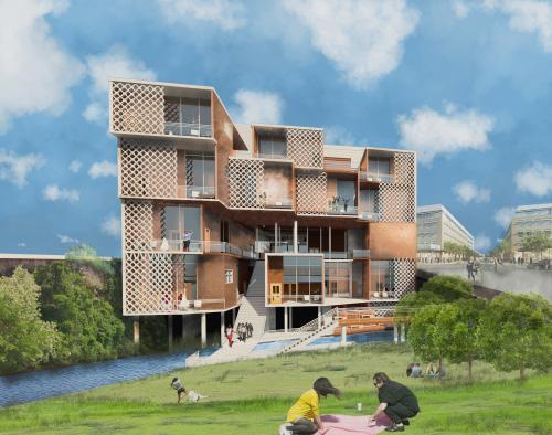
The Waller | Austin, Texas | Comprehensive Studio | Prof. Peter Raab
A Boutique Hotel located near the active and popular 6th st. on the intersection of Red River St. and 8th St. neighbors a particular creek named Waller Creek, hence the name.
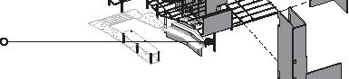
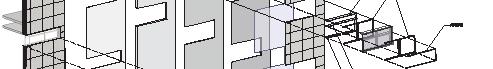
The concept is based off a Parti Diagram that presents an outer shell of the structure which is used to shell its users from the loud urban enivironment that surrounds it, while the Units/ Pods use their materiality to guide users to privacy as the Pods shift towards the creek.
(A) Based off the differences materials’ have in thickness sets a sequence of hierarch - Thin to Thick.
(B) This sequence acts as a guide for circulation.
(C) Thicker materials act as a shell or protector from the public, while less thicker materials act as navigators for users to circulate within the membrane of the building.
09
10
Exterior Perspective


11 Ground Level 1 FF_Plan
Below Ground Level_Plan


12 Level 3 FF_Plan Level 2 FF_Plan
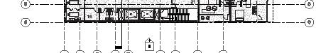
13 Longitudinal Section
14 Cross Section

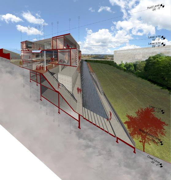
15 Transection Perspective


16 Program Diagram Roof Bar Walkway Units/ Pods Fitness Center Core Spa Area Main Bar Lobby Restroom Public Semi-Private Private
Private v. Public Diagram
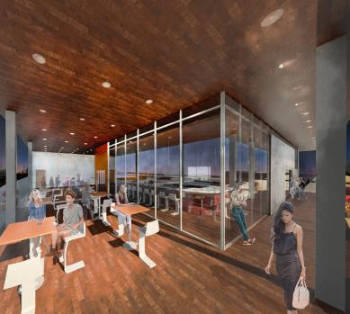
Interior Perspective
17 East Elevation
North & South Elevation
West Elevation
Structural


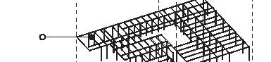


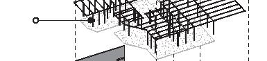


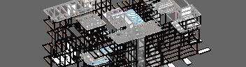

Exploded Axon
Load Analysis
Structure
HSS Rect. 8X12X3/8 Steel Beam
HSS Rect. 8X8X3/8 Steel Column
12” Concrete Retaining Wall
18
Concrete Column 10”X10”


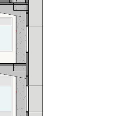
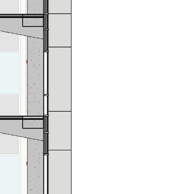
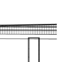
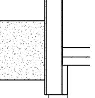
Exploded Axonometric Wall Section Analysis 19 Wall Section


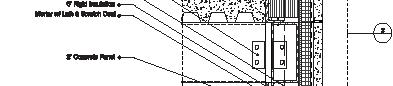


20 Wall Section | Details
Detail_02
Detail_01
Detail_03
21 Perspectives
22
Professional Experience | PhiloWilke Partnership
23
24
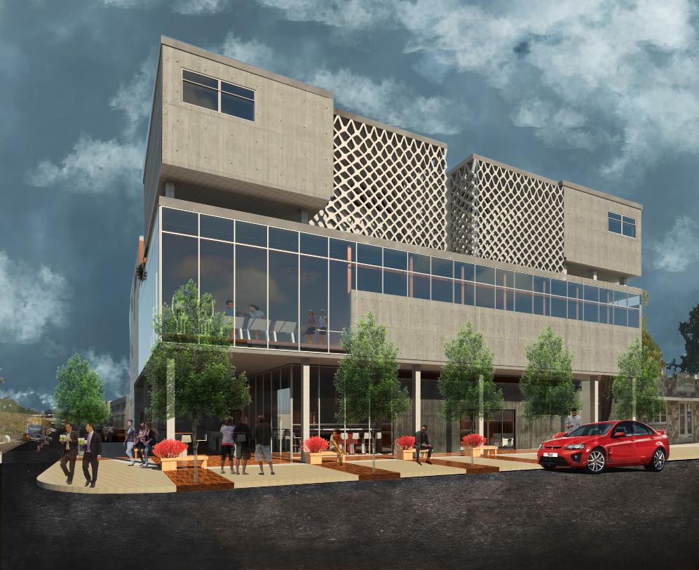
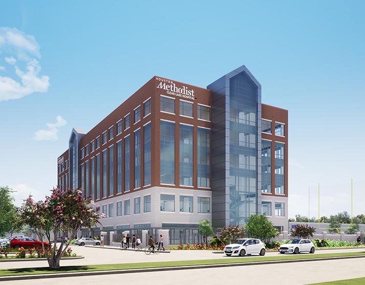
Houston Methodist Clear Lake Hospital: New Ortho Medical Office Building | 18123 Upper Bay Dr, Houston , TX, 77058
Project Information:
158,000 gsf
6 stories: Levels 1-2 build out, Levels 3-6 shell
Completed in April 9, 2021
Project Scope:
A new six story Medical Office Building located on the Houston Methodist Clear Lake Hospital campus. The Orthopedic functions on levels one and two, while the top four levels are shell space. The project does not rely on the campus central utility plant but is essentially free-standing. The project included the development of the site for parking, connections to adjacent drives and the outdoor physical therapy yard.
Key Roles:
Architectural designer in charge of various efforts throughout the entire design process, from SD to CA work. Developed schematic designs for floor and ceiling layouts, modeled exterior and interior building components, exterior and interior details, door hardware, finishes, submittals, RFIs, on-site field reports and coordination meetings with oversight from a Project Manager.
25
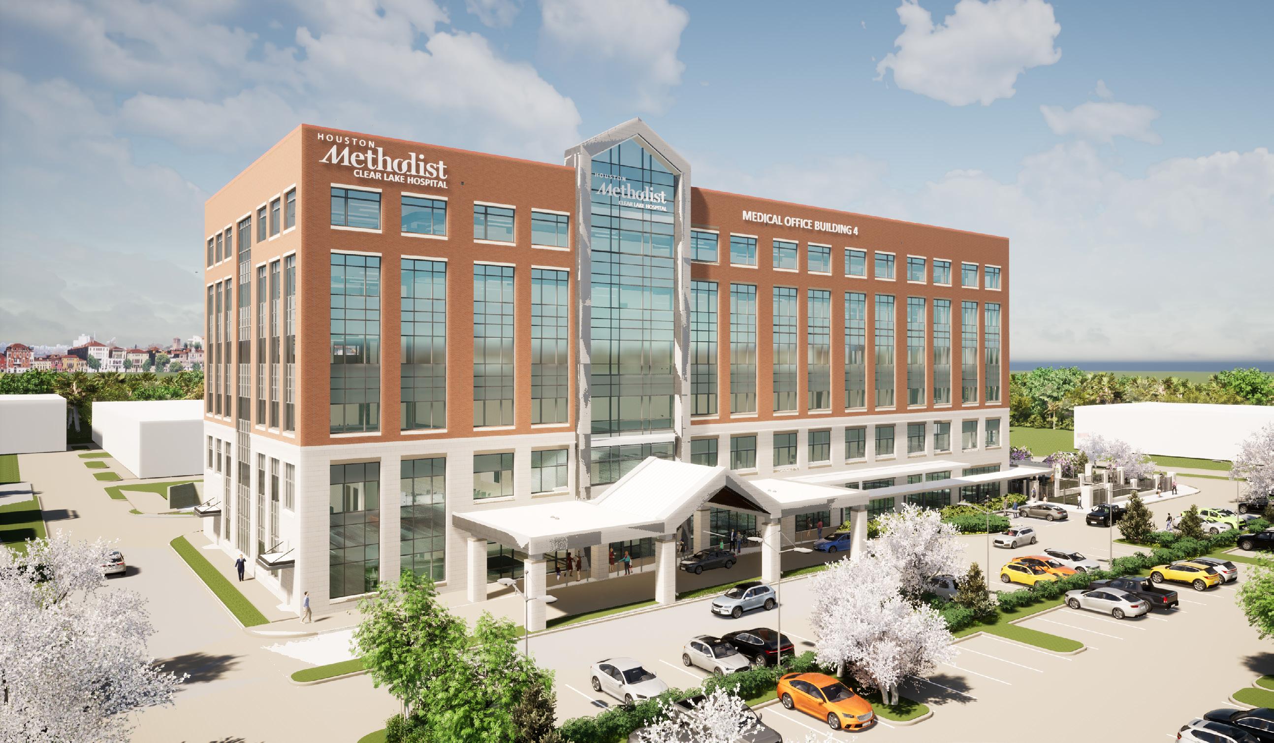
Houston Methodist Clear Lake Hospital: New Ortho Medical Office Building | 18123 Upper Bay Dr, Houston , Texas 77058

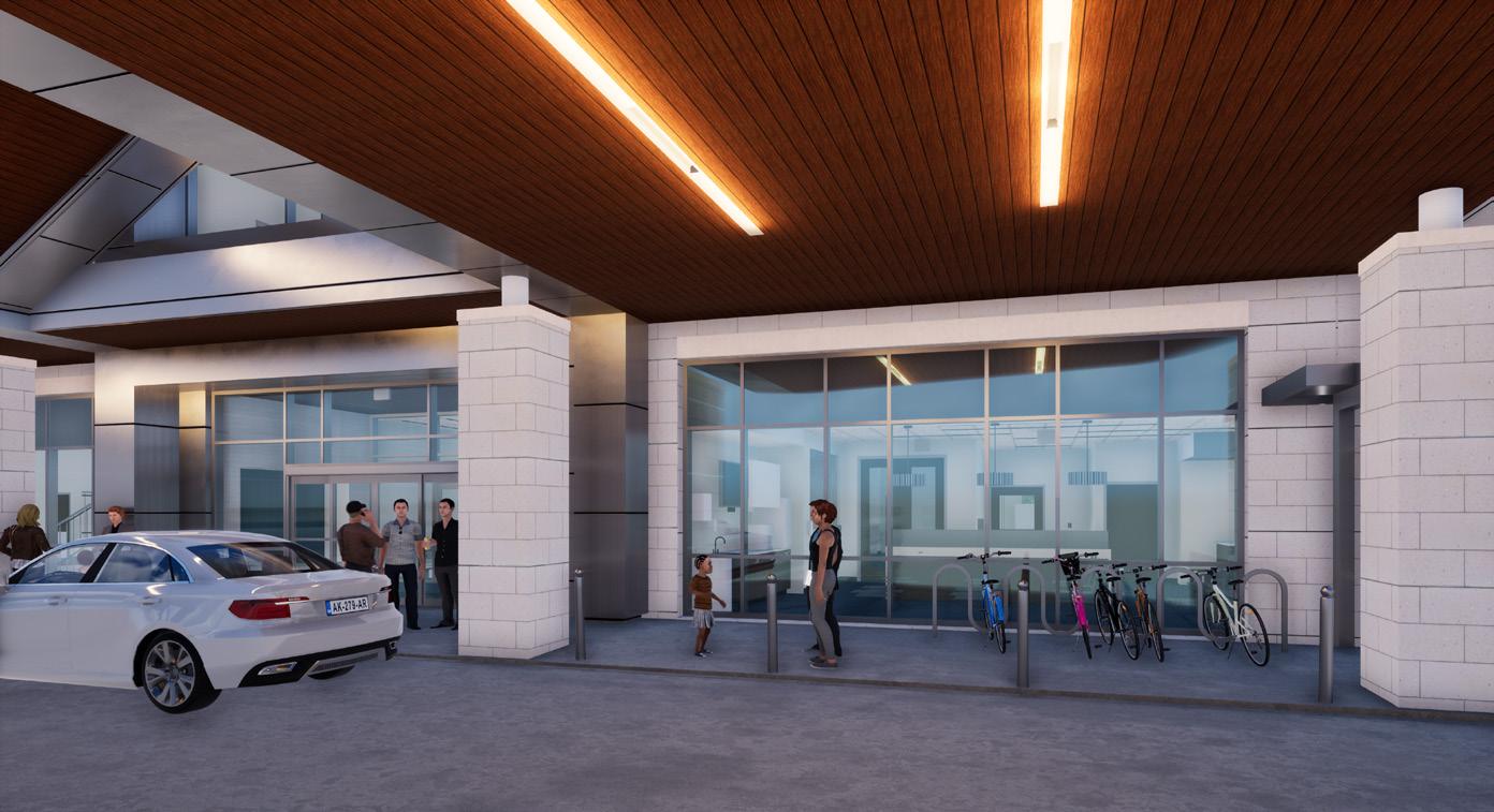
Main Entrance at Canopy:
Exterior Materials:
Canopy: Metal composite material panel
Ceiling: Suspended linear metal soffit system
Columns: Cast stone brick
26


27
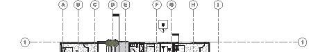
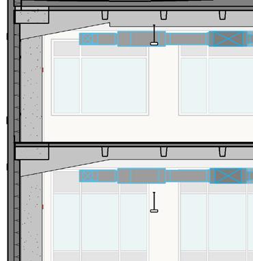
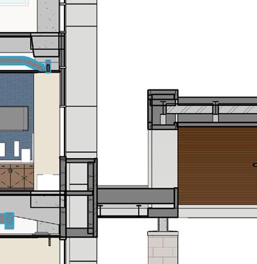
Ortho Medical Office Building |18123 Upper Bay Dr, Houston , TX, 77058 Level 1 - Finished Slab 0' - 0" Level 2 - Finished Slab 16' - 8" Level 3 - Finished Slab 32' - 8" Level 4 - Finished Slab 46' - 8" Level 5 Finish Slab 60' - 8" Level 6 Finish Plan 74' - 9" Top of Roof Slab 88' - 8" A B C D Top of Parapet 96' - 8" Top of Penthouse 105' - 0" Penthouse 89' - 8" A-320 1 A-321 21 Elevator Pit -5' - 6" Bottom of Deck 99' - 2 1/2" Top of High Parapet 101' - 2" OPH A-321 21 Sports PT Area 1121 Storage 1127 Electrical 1006a IT 1007 Entrance Lobby 1001 Vestibule 1000 Waiting 2000 IT 2004 Electrical 2005 Shell Space 2168 Exam 38 2174 Shell 3001 Corridor 3100 Electrical 3102 IT 3103 Corridor 3100 Shell 3000 Shell 4000 Corridor 4100 IT 4103 Electrical 4102 Corridor 4100 Shell 4000 Shell 5000 Corridor 5100 Electrical 5102 IT 5103 Corridor 5100 Shell 5000 Shell 6000 Corridor 6100 IT 6103 Electrical 6102 Corridor 6100 Shell 6000 A-320 25 P&W Commission Number Copyright (C) 2019 by PhiloWilke This document and the information part hereof shall be copied, duplicated, whatsoever except as expressly authorized or corporation receiving this document, deemed to have agreed to the forgoing trust and confidence subject only Partnership. Drawing Name Project Issues / Revisions Print Date / Time: 10/17/2019 218-111 Building 18123 Upper 77058 Ortho Medical Office Building 5177 Richmond Houston, TX 77056 Low Voltage Engineer Evergreen 1500 Marina Bay Clear Lake Shores, 1/8" = 1'-0" Transverse Section 1 No.Date 110/17/2019Permit, Transverse Building Section | Main Entrance
HMCL
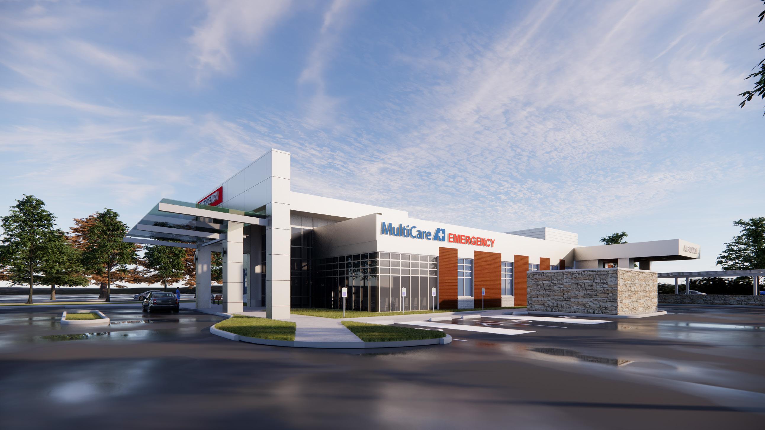
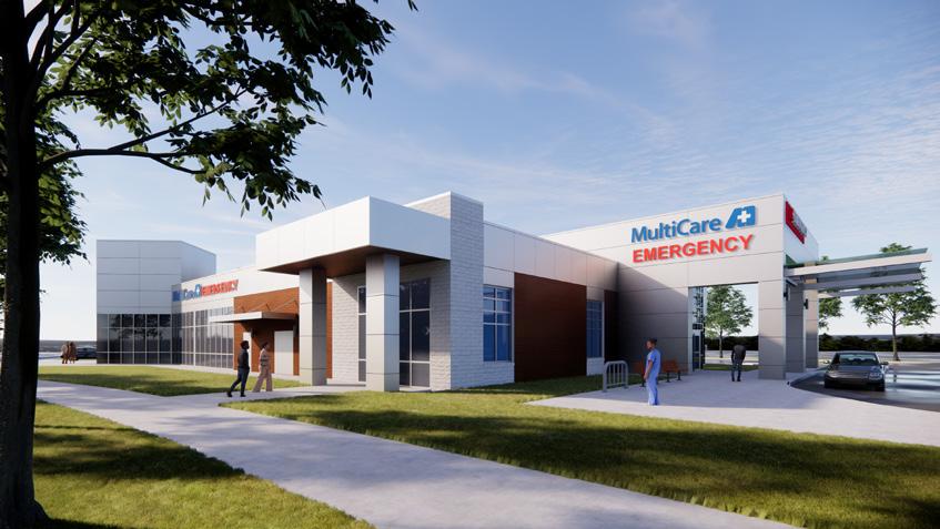
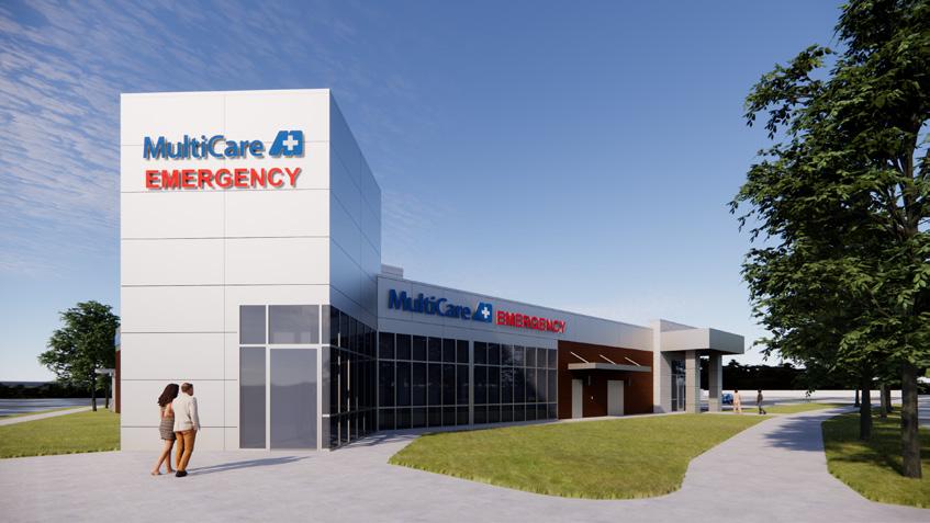
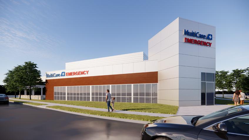
MultiCare Health System: Free-Standing Emergency Center (FEC) - Lacey | 5180 Yelm Hwy SE, Lacey, Washington 98503
Project Information:
9,600 gsf
1 Story: Emergency Center
Completed in December 12, 2023
Project Scope:
A new one-story emergency center located in Lacey, Washington. The Emergency center included ten (10) exam/ treatment rooms, and their required services, spaces, and systems needed to accommodate the clinical program. The project was reviewed under the State of Washington’s health facility laws and regulations.
Key Roles:
Architectural designer tasked primarily on developing exterior details and a few interior construction details. The exterior facade of the project contained extruded aluminum wall siding, metal composite material wall panels, adhered stone masonry, and stone masonry exterior walls. Exterior details included; typical plan details, roof details, material transition details, ext. wall base details, fascia and parapet wall details.
29

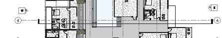
4 ADA 3 A-200 1 A-200 A-200 5 A-200 10 A00 Z61 Z61 17 30F A20 52 A20 30 M20x B00x Z61 32F A20 Z61 Z61 U66 Z61 13 7FP N14e 52 B04x 41 32F A24 A24 50AP N14e 28 A00 A00 Z61 E04 E04 2 2 3 3 5 5 A A C C C.3 C.3 D D 4.5 4.5 B.7 B.7 5.3 5.3 1.8 1.8 2.4 2.4 D.4 D.4 3.1 3.1 C.5 C.5 4.4 4.4 3.9 3.9 2.5 2.5 C.1 C.1 C.4 C.4 3.2 3.2 4.1 4.1 B B 3 A-320 A-320 A-310 6 A-321 26 A-320 A-401 A-403 A-403 A-400 A-406 A-405 A-403 A-300 A-300 A-300 A-300 A-300 A-300 ED112 Patient Tlt. ED103 Public Tlt. ED115 Exam ED101 Vestibule ED116 Exam ED117 Clean Supply Room ED123 Exam ED139 Equipment Alcove ED111 Exam/Isolation ED157 Office ED111a Patient Tlt. ED114 Exam ED113 Triage ED119 Major Exam/ Treatment/Trauma ED155 Office/ Dictation ED126 Storage ED118 Exam ED121 Exam ED122 Exam ED143 Mechanical/Vacuum ED124 Soiled Work Room ED197 HSKP ED168 Patient Tlt. ED175 Medication ED174 Lab ED206 Engineering Office ED205 Equipment Storage ED172 Records/ Support ED170 Registration ED180 Staff Lounge ED176 Office ED179 Staff Tlt. ED242 Nurse Station ED238 Corridor ED227 Waiting Area ED142 MDF ED226 Corridor ED152 Staff Tlt/ Shower ED210 Corridor ED212 Control Room ED171 Nourishment A-400 11 A-320 16 A-320 21 A-320 A-320 A-320 10 10 9 8 11 A-320 A-321 11 A-321 1 A-320 11 A-320 A-320 17 A-201 A-201 A-201 24A-200 A-2021 0 A-201 16 A-210 13 A210 A210 A-2022 0 21 A-201 26 A-201 A-210 A210 14 A-210 22 -210 4A-210 14 A-210 2 3 4 5 6 7 8 1 A210 A-403 6210 17A210 B2S D2 C2 D2S D2 C3S C2S C3S P2 C3S D2S C3S C3S D2 P2 P1 D2S D2 C3S P2 C1S D3S C2S C2S P2 P2 P1 P1 P1 C3S C2S D3S D2S C2S D2S D3S D3S C3S C2S D2S D2S C1S C3S D2S B2 B2 P2 P2 P2 C3 J2S D2S D3 D2S C3S H2S ED254 General Storage ED256 Electrical ED255 Med Gas A00 26 A401 ED264 CT Room ED267 X-Ray Room ED265 Vitals A03s 32F A00 33a 30F A20 31a 53 J65 A20 32F A20 26 -401 26 A-401 SIM C1S C3S C3S SIM A-320 A-320 SIM 21210 14 A402 A-404 A-542 22 A-542 22 A-542 22 A-542 22 A-542 22 SIM A-542 22 SIM 18210 6 A561 SIM 9 A-515 13500 10 10 A-543 19 11 12 PhiloWilke Commission Number Sheet Number Copyright (C) 2020 by PhiloWilke Partnership. All rights reserved. This document and the information herein the property of PhiloWilke Partnership. No part hereof shall be copied, duplicated, distributed, disclosed or used to any extent whatsoever except as expressly authorized by PhiloWilke Partnership. Any Person, firm, corporation receiving this document, however obtained, shall by virtue hereof, be deemed have agreed to the forgoing restrictions and that this document will be held trust and confidence subject only the private us expressly authorized by PhiloWilke Partnership. Drawing Name Project Issues Revisions Consultants Print Date Time: 6/2/2022 12:55:57 PM A-111 217-012-03 Floor Plan MultiCare Health System Off-Campus Emergency DepartmentLacey 4312 Pacific Avenue SE, Lacey, WA 98503 Civil and Landscape Consultant KPFF 612 Woodland Square Loop SE, Suite 100, Lacey, Washington 98503 Structural Consultant Axiom 121 N. 9th St., Suite 401, Boise, Idaho 83702 MEP Low Voltage Security Consultant Telios 101 Parklane, Suite 101, Sugar Land, Texas 77487 PN 1/8" = 1'-0" First Floor -Architectural Plan 1 1. All new partitions are type "C2S" unless noted therwise. 2. All dimensions are to face of gypsum board or face of masonry unless noted 3. See 1 A-520 for Partition Type Schedule. 5. See 21 A-600 for Door Hardware Schedule. 6. All exposed structure to be painted to match aluminum mullions. No.Date 106/02/2022Issued for Pricing and Permit
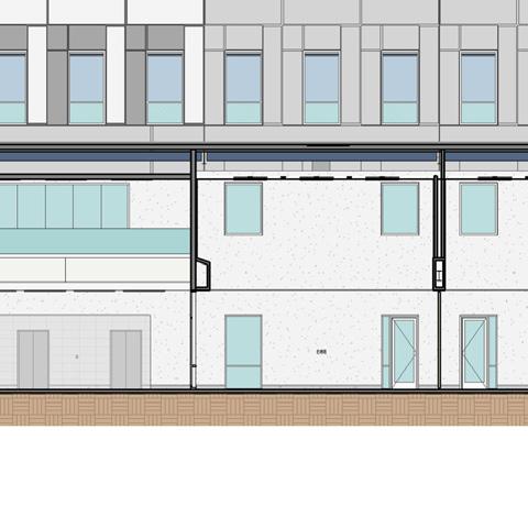
Materials:
Walls: Extruded Aluminum Wall Siding Metal Composite Material Panel Stone Masonry
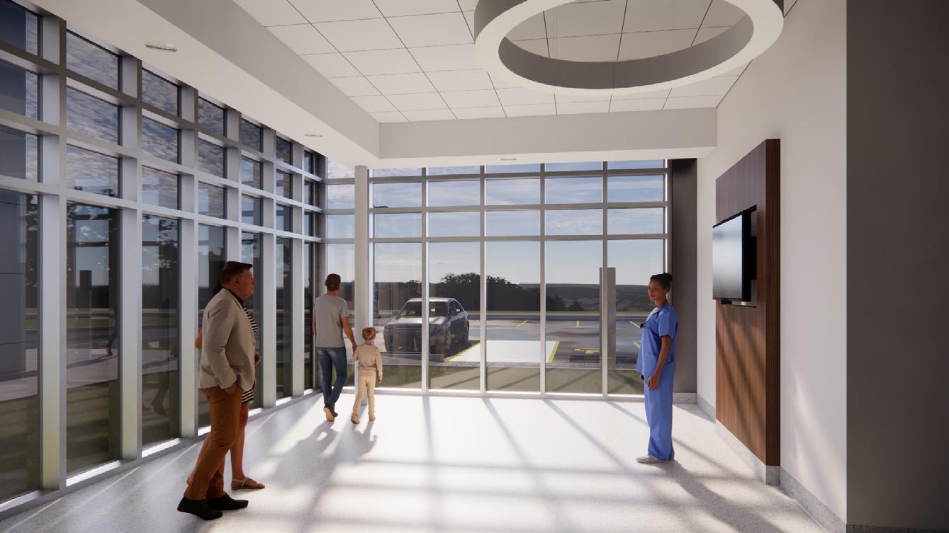
Metal composite material panel Suspended linear metal soffit system Waiting Area Interior Perspective View 30
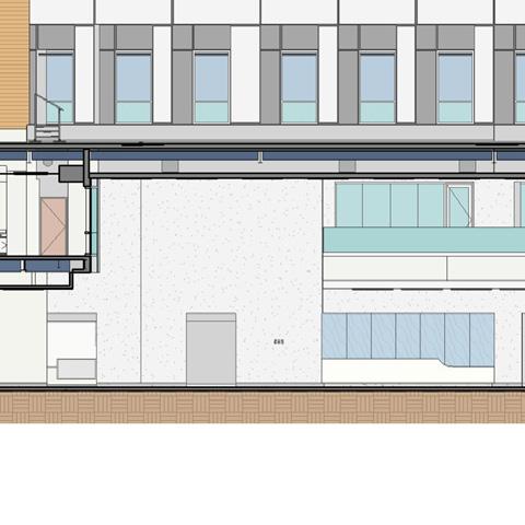
Exterior
Exterior
Canopy:
31
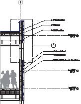
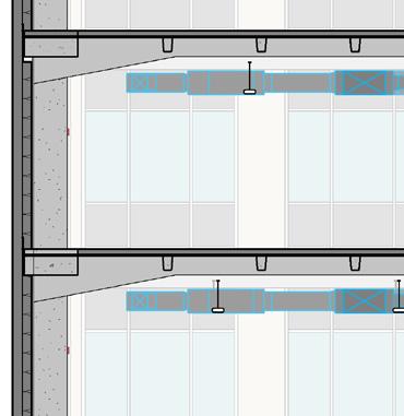
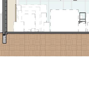
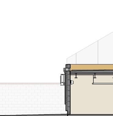
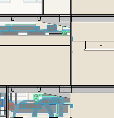
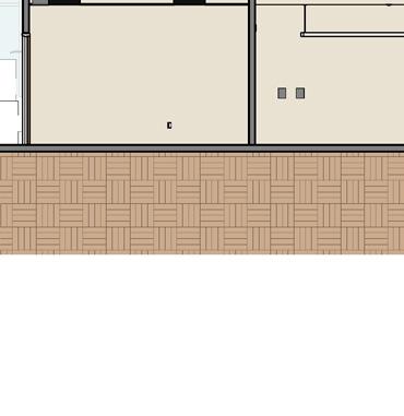
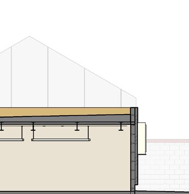
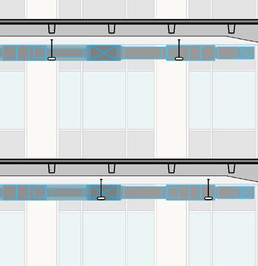
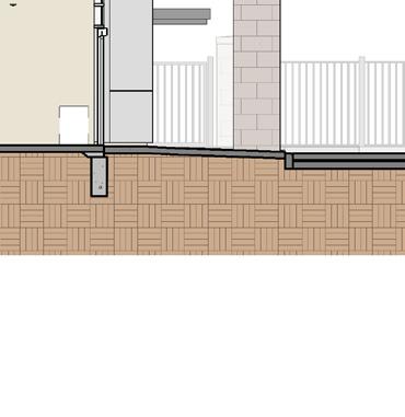
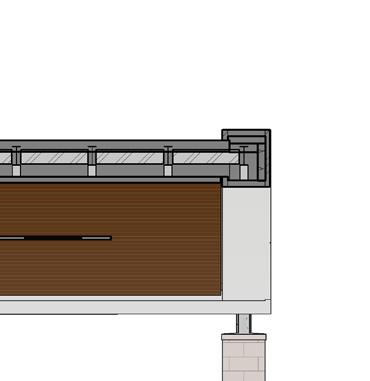
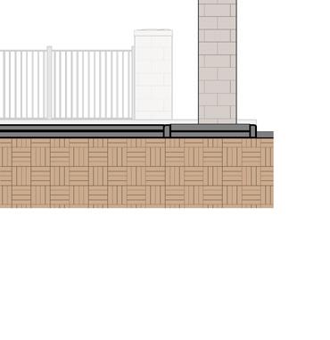
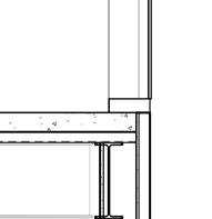
Health System: Free-Standing Emergency Center (FEC) - Lacey |5180 Yelm Hwy SE, Lacey, WA 98503 Finished Slab 0' - 0" Bottom of Deck - Low Roof 16' - 0" 5 4.5 5.3 4.4 6 6 A-321 Top of Parapet - Low Roof 19' - 0" Top of Parapet - High Roof 26' - 0" A-502 23 A-502 4 3' - 0" A-502 3 4' 0" 2'8 1/2" 5'3 1/2" 2'1 1/4" 2' 11 1/4" 8'11 1/2" A-523 14 A-543 6 A-541 2 A-541 1 A-541 2 A-541 1 A-523 4 A-321 4 A-523 11 48' 4" 1' - 6" 15' 3" 8' - 8 1/2" 14' - 10 3/4" 5' 3" 2' 8 3/4" TPO membrane on 1/2" cover board on 7" rigid insulation on 1 1/2" metal deck Extruded aluminum soffit Recessed linear ceiling, see Reflected Ceiling Plan Metal composite soffit panels Signage Exterior lighting, see MEP Drawings Metal composite material wall panel R-10 Continuous perimeter insulation board Glazed canopy, see Specification section 13 31 00 A-504 9 O.H. PhiloWilke Commission Number Copyright (C) 2020 by PhiloWilke Partnership. This document and the information herein is the part hereof shall be copied, duplicated, distribute whatsoever except as expressly authorized by or corporation receiving this document, however deemed to have agreed to the forgoing restrictions trust and confidence subject only to the private Partnership. Drawing Name Project Issues Revisions Consultants Print Date / Time: 6/2/2022 12:57:31 217-012-03 Partial Building Sections MultiCare Health Off-Campus Emergency Department Lacey 4312 Pacific Avenue SE, Lacey, WA 98503 Civil and Landscape Consultant KPFF 612 Woodland Square 100, Lacey, Washington 05/19/2022 Structural Consultant Axiom 121 N. 9th St., Suite 401, Boise, Idaho 83702 MEP / Low Voltage / Security Telios 101 Parklane, Suite 101, Sugar Land, Texas 77487 1/2" = 1'-0" Partial Building Section -Main Entrance 1 No.Date 106/02/2022Issued Partial Building Section | Main Entrance
MultiCare


Metal deck, see Structural Framing Details
Metal composite material wall panel, see 2 A-500 for wall assembly
Steel beam, see Structural Framing Details
Scheduled ceiling, see Reflected Ceiling Plan for locations, types, and height
Aluminum curtain wall system
TPO roof membrane over 1/2" Roof cover board on R-38 rigid insulation board Steel beam, see Structural Framing Details
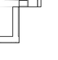
32 C.3 Bottom of Deck - Low Roof 16' - 0" 4.4 Top of Parapet - Low Roof 19' - 0" Top of Parapet - High Roof 26' - 0" A-502 8 A-502 19 A-523 14 A-542 23 A-522 23
Roof cover
insulation board
TPO roof membrane over 1/2"
board on R-38 rigid
1" insulated glazing
GREGORY LYNN JOHNSON STATE OF WASHINGTON REGISTERED ARCHITECT 11803 Suite 200 | Houston, Texas 77031 832.554.1130 | philowilke.com Issues / Revisions Consultants Civil
KPFF 612
100,
Structural
Axiom 121
MEP
Telios 101
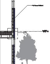
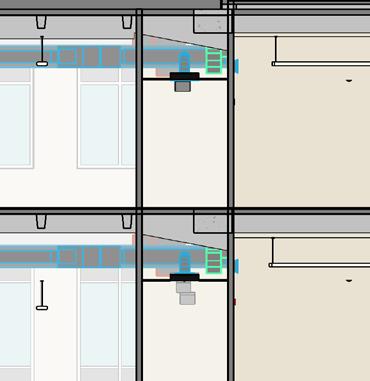
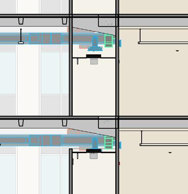
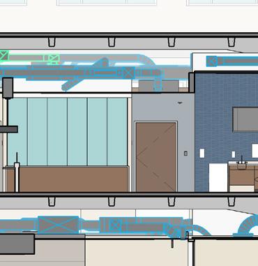
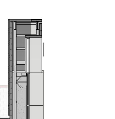
1/2" = 1'-0" Clearstory Curtain Wall Section 4 Grid EQ EQ See Enlarged Plan D See Enlarged Plan Metal composite material wall panel, provide panel stiffener as required Fiber glass mat face gypsum sheathing Metal stud Sealant and backer rod WRB/air barrier membrane First Floor -Top of Slab 0' -0" Gypsum board Metal stud with batt insulation Exterior gypsum board Concrete grade beam, see Structural Foundation Details .063 Pre-finished aluminum flashing 6"x 8" Concrete curb, See Structural Drawings See wall section 6" Mineral fiber board insulation 10 1/4" 2' 1/2" 6 1/2" 4 1/2" 1/4"1/2"6" 3" See Wall Section 18'-0" to First Floor -Top of Slab 1' 6" Slope TPO roof membrane on 1/2" roof coverboard over tapered insulation 1/2" TPO QS flashing, see specifications Slope Continuous bead of TPO sealant to wrap entire support Screen Support, see Structural Roof Framing Drawing Grid Bottom of Deck -Low Roof 16' -0" Wide flange, see Structural Roof Screen wall Details See Wall Section See Wall Section 1'-4" minimum Stainless steel camping ring 1/4" roof board Roof membrane See wall section 3/4"1/2"6"1/2"4 3/4" Roof cover board Grid Top of Parapet -High Roof 26' -0" 1' 1/2" 1' 3 1/2" 5"1/2" Fire treated plywood sheathing See 2 A-500 for typical wall assembly 1/2" Backer rod and sealant Metal composite material wall panel 1/2" Shim M 6 TPO roof membrane on 1/2" roof coverboard on tapered insulation Metal composite material wall panel, provide panel stiffener as required WRB/air barrier membrane adhered to fire-rated pressure-treated plywood 6" metal studs 1/4"1/2"6"1/2" 1/4" 1/2" Backer rod and sealant Steel angle, see Structural Framing Details 1' 1/2" Bottom of Deck -Low Roof 16' -0" Fastener at 16" o.c. Double dry gasket for air/water seal Shim panel as required 224 1 2 4 1 / 4" 1/2" Roof cover board Roof membrane Aluminum curtain wall mullion 1" Insulated glass Metal stud with batt insulation WRB/air barrier membrane on 1/2" fire treated plywood sheathing 1/2" Fiber glass mat face gypsum sheathing exterior sheathing Mineral fiber insulation WRB/air barrier membrane Metal stud 1/2" fire treated plywood sheathing WRB/air barrier membrane Metal composite material wall panel 3 1/2" 1' 0 1/4" 1' 3 3/4" 1/2" 1 5/8" galvanized metal furring Steel angle support and bracing Sealant and backer rod Extruded aluminum soffit 2 1 / 2 1 2 See Wall Section Galvanized clip angle See Wall Section 1' 11 1/4" Pre-finished aluminum flashing WRB/air barrier membrane See wall section Metal composite material wall panel, provide panel stiffener as required 3 5/8" metal stud 6" Minimum 7/8"1/2"3 5/8"1/2"2 1/4" Bent plate see Framing Details WRB/air barrier membrane Bottom of Deck -High Roof 24' -6" Top of Parapet -High Roof 26' -0" Grid Steel beam see roof level 1/2" Backer rod and sealant Metal deck see Framing Details Fire treated plywood sheathing 5 1 2 9 3/4" 1' 6" Roof membrane 16 Tapered insulation 1/2" Shim See Wall Section 1/4"1/2"6" 7 8 1 2 6 1 / / 8 14'-0" to First Floor -Top of Slab See Wall Section C U e \ m o n e \ D o c u m e n \ R e L c a 2 10 1 20 3 M u C a e a e y ( 0 2 1 m o n e r MCM Canopy Column Section -Ambulance 3" 1'-0" MCM Canopy Wall Base -Ambulance 16 MCM Section at Main Entrance 3" 1'-0" Screen Wall Roof Penetration Detail 24 3" 1'-0" Metal Coping at MCM Wall 18 3" 1'-0" MCM Roof Canopy Fascia -Ambulance 8 3" 1'-0" Typical MCM Fascia at Curtain Wall -Emergency Entrance 19 3" 1'-0" MCM Roof Canopy Fascia Main Entrance 23 Detail Section MCM at Main Entrance Metal linear soffit at Ambulance Canopy MCM Fascia at Curtain Wall | Clerestory Curtain Wall Section | Various Condition Details EQ See D See Enlarged Plan Metal composite material wall panel, provide panel stiffener as required Fiber glass mat face gypsum sheathing Metal stud WRB/air barrier membrane Gypsum board Metal stud with batt insulation Exterior gypsum board .063 Pre-finished aluminum flashing 6"x 8" Concrete curb, See Structural Drawings See wall section Mineral fiber board insulation 10 1/4" 2' 2 1/2" Slope TPO roof membrane on 1/2" roof coverboard over tapered insulation 5 1/2" TPO QS flashing, see specifications Slope Continuous bead of TPO sealant to wrap entire support Screen Support, see Structural Roof Framing Drawing Grid Bottom of Deck -Low Roof 16' -0" Wide flange, see Structural Roof Screen wall Details See Wall Section See Wall Section 1'-4" minimum Stainless steel camping ring 1/4" roof board Roof membrane See wall section 2 3/4"1/2"6"1/2"4 3/4" Roof cover board Grid Top of Parapet -High Roof 26' -0" 1' 2 1/2" 1' 1/2" 5"1/2" Fire treated plywood sheathing See 2 A-500 for typical wall assembly 1/2" Backer rod and sealant Metal composite material wall panel 1/2" Shim M m u m 6 3 1/4"1/2"6"1/2" 2 1/4" 1' 0 1/2" Bottom 16' -0" 1 2 4 1 / 4" Aluminum curtain wall mullion 1" Insulated glass Metal stud with batt insulation WRB/air barrier membrane on 1/2" fire treated plywood sheathing 1/2" Fiber glass mat face gypsum sheathing exterior sheathing Mineral fiber insulation WRB/air barrier membrane Metal stud 1/2" fire treated plywood sheathing WRB/air barrier membrane Metal composite material wall panel 1/2" 1' 1/4" 1' 3/4" 7 1/2" 5/8" galvanized metal furring Steel angle support and bracing Sealant and backer rod Extruded aluminum soffit 2 / 2 1 2 See Wall Section Galvanized clip angle See Wall Section 1' 11 1/4" Pre-finished aluminum flashing WRB/air barrier membrane See wall section Metal composite material wall panel, provide panel stiffener as required 5/8" metal stud 6" Minimum 2 7/8"1/2"3 5/8"1/2"2 1/4" Bent plate see Framing Details WRB/air barrier membrane Bottom of Deck -High Roof 24' -6" Top of Parapet -High Roof 26' -0" Grid Steel beam see roof level 1/2" Backer rod and sealant Metal deck see Framing Details Fire treated plywood sheathing 5 / 2 3/4" 1' 6" Roof membrane 16 Tapered insulation 1/2" Shim 3" = 1'-0" Screen Wall Roof Penetration Detail 24 3" = 1'-0" Metal Coping at MCM Wall 18 MCM Roof Canopy Fascia -Ambulance 3" = 1'-0" Typical MCM Fascia at Curtain Wall -Emergency Entrance 19 3" = 1'-0" MCM Roof Canopy Fascia Main Entrance 23 C.3 7" 1' 2 1/2" 1/2" A-543 5 4500 5 1 / 1 1 7 1 / C.3 11 1 2 Metal flashing TPO Roof membrane Rigid roof insulation 1/2" Metal decking 1/2" Roof cover board Steel beam, see Structural drawings Steel bend plate, see Structural drawings 5/8" gypsum board 6" metal stud with batt insulation 1/2" roofing board Aluminum curtain wall mullion 1" insulated glazing 4500 3-5/8" metal stud 4.4 1' 3/4" 1/2" 9 1/4" A-543 SIM S p /4 e o p c 8 Vapor retarder 1/4" roof board Scheduled ceiling where occurring Shim and sealant over backer rod each side Scheduled partition Built-up stud & track header Corridor side Exam room side Gypsum board 'J' mold at exposed edges, both sides Scheduled door opening E Q 2 1/8" Neoprene compressible filler, provide fire rated compressible gasket at fire rated assemblies, see Fire Safety Plans Alum. trim to match window mullion finish, attach with clips at top and bottom, do not screw into mullion 1/2" 1 4 C Sealant Aluminum-framed Curtain wall window mullion WRB/air barrier membrane over aluminum flashing Grid J-track to match Extruded aluminum wall finish Outside corner to match Extruded aluminum wall finish 12 3 8 3 Sealant and backer rod Pre-finished aluminum flashing A-550 22 Extruded aluminum wall siding, see A-500 for wall assembly Alum. L-clip with thermal break at 2'-8" o.c. vertical Exterior 6'-0" See Elevation Aluminum-framed Curtain wall window mullion WRB/air barrier membrane Grid Pre-finished aluminum flashing Sealant and backer rod A-550 22 3 12 3 8 Stone Masonry, see A-500 for wall assembly 6'-0" See Elevation Exterior 3" = 1'-0" Clearstory Window at Roof -Sloped Wall 23 3" 1'-0" Typical Jamb Curtain Wall Detail at Extruded Aluminum Siding 29 3" = 1'-0" Typical Jamb Curtain Wall Detail at Stone Masonry 19 | MCM Roof Canopy Fascia | | Clerestory Window Sill at Roof
and Landscape Consultant
Woodland Square Loop SE, Suite
Lacey, Washington 98503 05/19/2022
Consultant
N. 9th St., Suite 401, Boise, Idaho 83702
/ Low Voltage / Security Consultant
Parklane, Suite 101, Sugar Land, Texas 77487
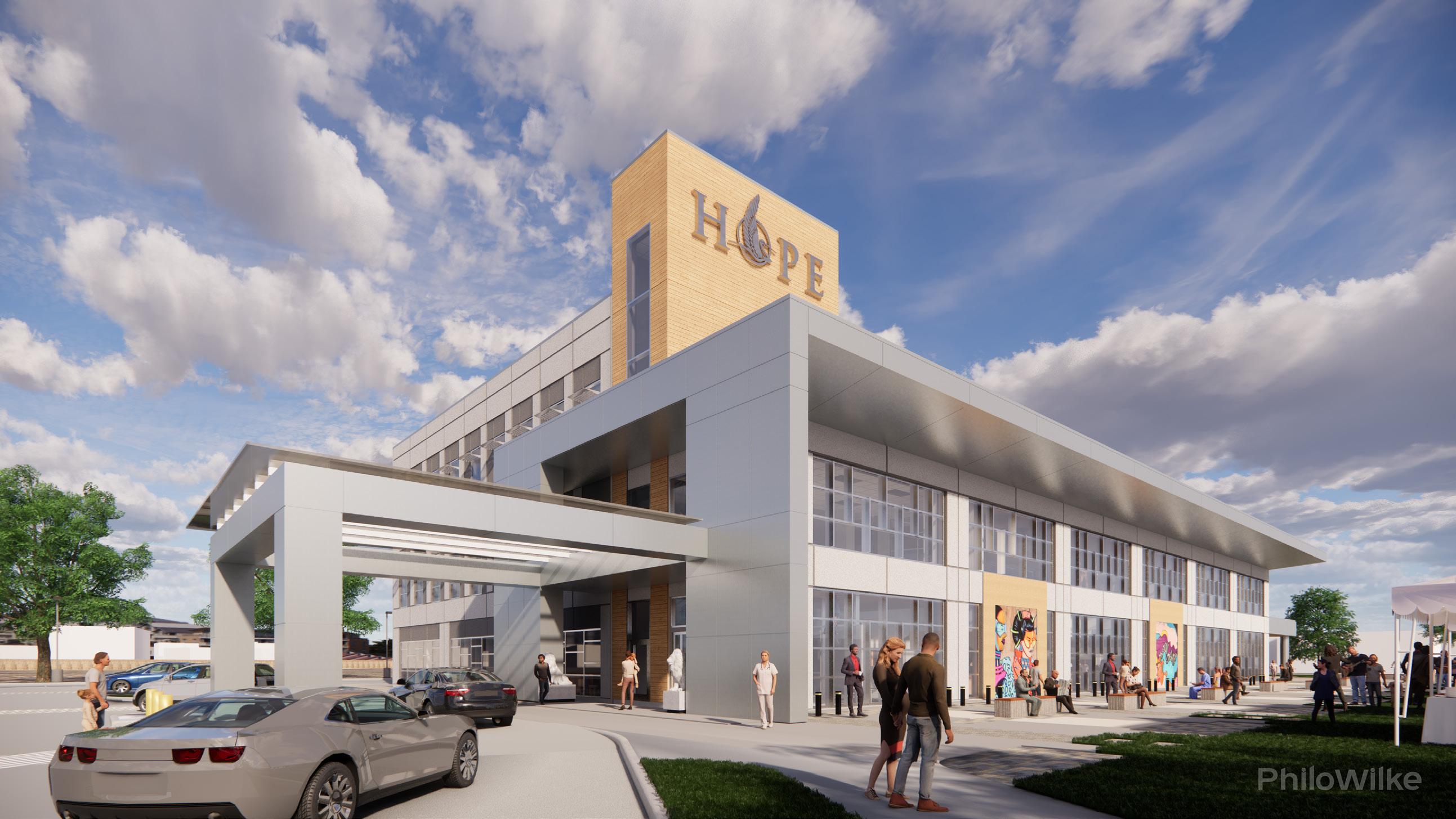
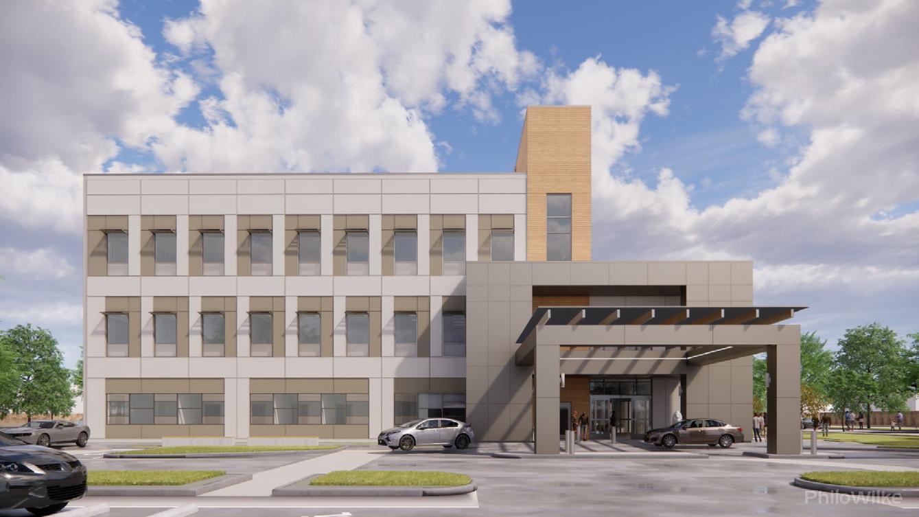
Hope Clinic Health and Wellness Center | 13930 Bellaire Blvd. Houston, Texas
Project Information:
80,000 gsf
3-story level: Healthcare Facility
Completed in July 18, 2023
Project Scope:
A new three-story outpatient center with multiuse facilities and the development of site work, paving, drainage, and other improvements.
Key Roles:
Architectural designer in charge of various efforts throughout the entire design process, from SD to CA work. Developed schematic designs for floor and ceiling layouts, modeled exterior and interior building components, exterior and interior details, door hardware, finishes, submittals, RFIs, on-site field reports and coordination meetings with oversight from a Project Manager.
33
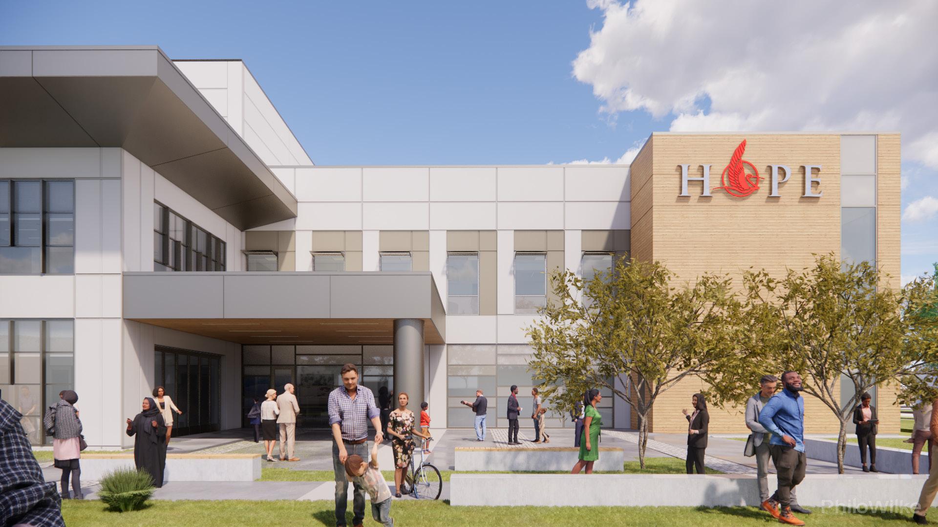
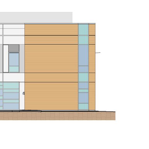
Exterior Materials:
Exterior Walls:
Metal linear wall siding
Metal composite material wall panels
2” recessed painted concrete tilt wall system
Glazed aluminum curtain wall system
Aluminum framed storefront wall system
Canopy: Metal composite material panel
Suspended linear metal soffit system
|
Elevation |
South
Waiting Area Interior Perspective View 34


35
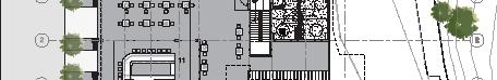
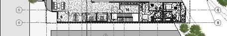
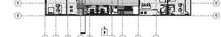
Level 1 Floor Plan | Focal Point: Main Lobby and Public Waiting Legend: Rendering Views 1. 2. #. UP UP UP A-201 1 A-200 A-200 A-201 1 2 3 4 5 6 7 8 9 10 A B C D E.1 A-300 A-300 A-301 A-301 3 A-300 A-300 A-406 1 A-301 A-301 10 1/2" 29' 0" 28' 6" 24' 2 3/8" 4' 3 5/8" 28' 6" 17' - 10 5/8"10' - 7 3/8" 28' 6" 28' - 6" 28' 6" 29' 0" 1' 2" 81' 11 3/8" 51' 11 1/4" 67' 10 3/4" 1/8" 57' 9" 1/8" 29' 9 1/2" 87'9 1/2" 11' 6" 18'8" Match Line: See 1 A-110 Match Line: See 1 A-111 Electrical Room IDF Room HSKP Staff Lounge/ Lockers Emergency Electrical Main Electrical Fire Pump Multipurpose Room Waiting Specimen Toilet Consult Exam 13 Exam 12 Exam 11 Staff Workstation Exam Exam Provider Work Room Procedure Room Exam Exam 6 Exam Exam Isolation Room Conf./ Resident Wk Room Drop-off/ Pick-up Pharmacy Breakroom Storage Work Room Trash/Recyclables Holding Area Service Elevator Lobby Men's Public Toilets Women's Public Toilets Public Elevator Lobby Multipurpose Room Public Elevator Stair Service Elevator Stair C Public Waiting Exam Triage Exam 14 Staff Toilet Patient Toilet Scale Alcove Patient Toilet Care Coord.Care Coord. Staff Workstation Seating Alcove Consult Exam 15 Pedi Triage Facilities Office Equipment Yard Receiving Office Supervisor Office Central Equip. Holding Housekeeping Cart Storage Bulk Storage Area Receiving/ Break-Out Area Radiographic Room Storage Pano X-Ray DA Work Area Shared Staff Lounge Sterilization Lab Vacuum/ Compressor Cafe Seating Food Preparation Area Medicaid Office Flex Office Eligibility Work Area Radiology Waiting Tech Workroom Staff Toilet Patient Toilet Dental Waiting Reception/ Business Office Doctor Office Operatory Operatory 2 Private Operatory 3 Private Operatory Operatory Operatory Back of House Storage Stairs A Storage Administrative Office Suite Reception/Security/ Check-In Public Corridor Public Elevator Blood Draw Lab Processing Waste Holding Testing Alcove Equipment Alcove Main Lobby Corridor Public Corridor Corridor Corridor Corridor Corridor Corridor Corridor Corridor Corridor Corridor Outdoor Covered Multi-Purpose Area (Future Food Service) Biohazard Storage Room Staff Toilet HSKP Ultrasound Patient Toilet Corridor Reception Private Consult 259' 6 1/2" 2'2"4"16' 4 3/4"11'3 1/4" 29' 0" 28' 6" 29'6" 10'8 1/2" 19'10 1/2" 42' 9 3/4" 174' 2" 54' 11 1/2" 30' 3" 3.7 5.5 X D.2 18A-510 3 A-510 E 8' 10 1/2" 3' 0" 27' 8" 1' 5 1/2" 1' 6 1/2" 8' 10 1/2" 118'0 1/2" Vestibule Entrance D.9 147' 9 1/8" Isolation Room Check-Out E.5 C.9 C.6 1' 5" 9' 0" 30'7 1/2" 9'0"1'4 1/2" 5' 0" 18' 6" 20' 0" 10' 0" 0.8 11275 S. Sam Suite 200 | Houston, 832.554.1130 ED A R E GISTE TE OF T S EXA R RCH TA V E Z T L U H TS E N 2 4 L SC CHAR ES P&W Commission Number Sheet Number Copyright (C) 2020 by PhiloWilke Partnership. All rights reserved. This document and the information herein the property part hereof shall be copied, duplicated, distribute disclosed whatsoever except as expressly authorized by PhiloWilke or corporation receiving this document, however obtained, deemed to have agreed to the forgoing restrictions and that trust and confidence subject only to the private us expressly Partnership. Drawing Name Project Issues Revisions Consultants Print Date Time: 11/24/2020 4:38:00 C:\Users\rcuellar\Documents\218-109 Hope ClinicR educed Option(2019)_rcuell123.rvt A-101 218-109 Level 1 -Overall Reference Plan Hope Clinic 13930 Bellaire Blvd. Houston, TX 77083 Civil and Structural Engineers Walter P. Moore 11/17/2020 MEP Engineer DBR Landscape Architects Kudela & Weinheimer Equipment Covalus Food Service Worrell Design Group, General Notes -Floor Plan 1. All dimensions are to face of gypsum board, unles noted otherwise. 2. Refer to Enlarged plans for interior wall types. 1" = 10'-0" First Floor -Architectural Plan 1 No.Date 111/17/2020Issued for Construction
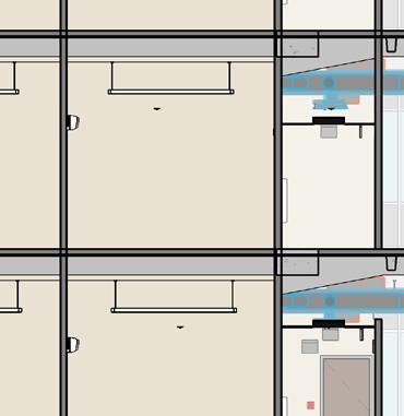
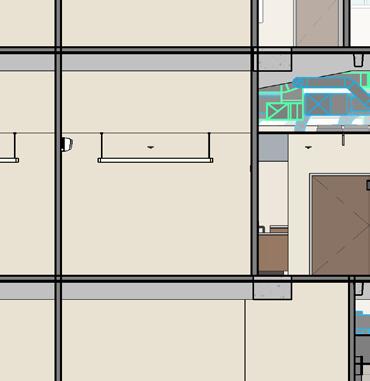
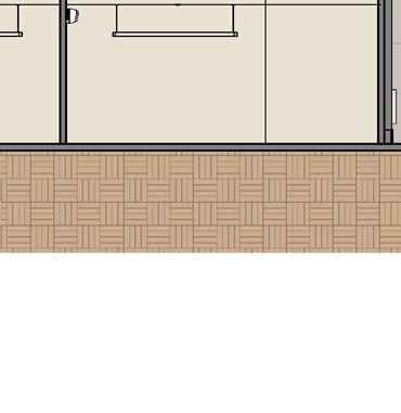
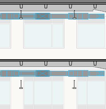
Hope Clinic Health and Wellness Center | 13930 Bellaire Blvd. Houston, Texas


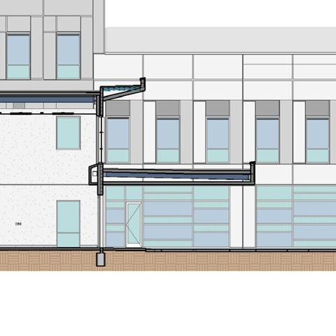
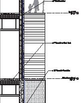
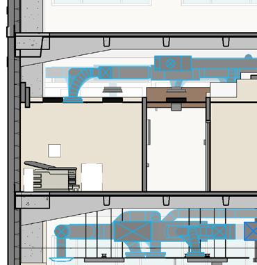
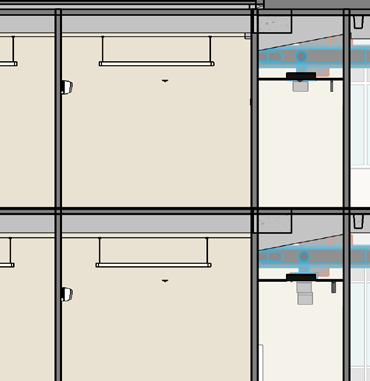
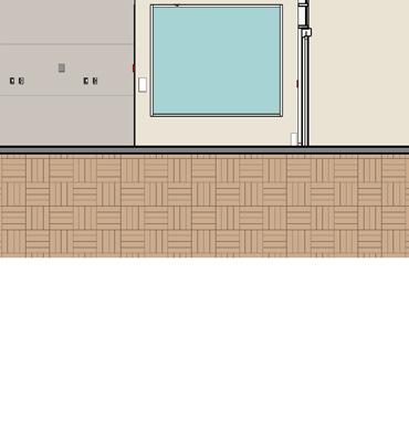
36 | Wall Section at Conference Room Glazing | First LevelFinished Slab 0' - 0" Second LevelFinished Slab 16' - 0" Third LevelFinished Slab 32' - 0" Roof - Main - High Point 48' - 0" 3 4 5 6 7 8 9 10 Top of ParapetHigh 52' - 0" A-323 14 Top of ParapetLow 37' - 0" A-320 26 A-320 A-323 21 3.7 5.5 A-523 23 0.8 First LevelFinished Slab 0' - 0" Second LevelFinished Slab 16' - 0" Third LevelFinished Slab 32' - 0" 1 2 3 4 5 6 7 8 9 10 A-409 11 A-323 16 A-323 11 A-406 4 3.7 5.5 A-324 26 0.8 A-301 16 Hope 3/32" = 1'-0" Longitunal Section 1 3/32" = 1'-0" Longitudinal Section -Lobby 3 First LevelFinished Slab 0' - 0" Second LevelFinished Slab 16' - 0" Concrete slab on grade over vapor barrier, see Structural Drawings 1/2" roof cover board over R-25 rigid insulation Linear metal ceiling 5" Concrete slab on 1 1/2" metal deck 16'0" 16'0" First LevelFinished Slab 0' - 0" Second LevelFinished Slab 16' - 0" 2 A-571 4 16'0" Concrete slab on grade over vapor barrier, see Structural Drawings 5" Concrete slab on 1 1/2" metal deck 4'0" Opening Height 12'0" Power operated Overhead Vertical Coiling Fire-Rated Door, see Specification 08 33 23 1-hour horizontal construction Type V497, see UL design 3 G-104 A-571 1 Second LevelFinished Slab 16' - 0" Linear metal ceiling 5" Concrete slab on 1 1/2" metal deck TPO roof membrane on 1/2" roof cover board over R-25 rigid insulation 4'0" 9'6" 6" A-521 9 A-521 20 Second LevelFinished Slab 16' - 0" A-542 6 9'6" 4'0" 1'0" 8'6" 2'0" 2'0" Linear metal ceiling 5" Concrete slab on 1 1/2" metal deck TPO roof membrane on 1/2" roof cover board over R-25 rigid insulation Scheduled ceiling Curtain wall system 5'7" 2'11" A-521 9 A-544 24 C:\Users\clozano\Documents\218-109 Hope ClinicRe duced Option(2019)_clozano.rvt 1/2" = 1'-0" Wall Section at Stud Partition -Stair A 1/2" = 1'-0" Wall Section at Overhead coil shutter 16 1/2" = 1'-0" Wall Section at Conference Room Bridge 21 1/2" = 1'-0" Wall Section at Conference Room Glazing 26 Third LevelFinished Slab 32' - 0" 1/8" 2" 7 3/4" 1' 1/4" Metal siding, see detail 24 A-500 Metal stud with Batt insulation, R13 typical Tilt-up concrete panel, see detail 11 A-500 Metal linear wall siding corner trim Gypsum board Spray applied fireproofing see 16 G-100 Tilt-up concrete panel 0.050" Prefinished aluminum flashing Steel angle Sealant TPO roof membrane on 1/2" roof cover board Tapered insulation on R-25 rigid insulation Aluminum curtain wall mullion Metal deck 1 Metal linear wall siding corner trim 0.050" Prefinished aluminum flashing, color to match mcm finish Metal composite material, see detail Backer rod and sealant 3" 1' 8 1/4" 3/4" Interior Exterior 11 1/8" 3/8" 1' 1/2" 2' 1 1/2" Minimum 8" TPO roof membrane under counter flashing Metal counter flashing with sealant and fasteners Second LevelFinished Slab 16' - 0" 2" 3/4" 1' 8 1/4" 2' 2" Continuous mineral fiber board insulation, R10 Typical Metal stud with Batt insulation, R13 typical Tilt-up concrete panel, see detail 11 A-500 Metal linear wall siding corner trim Gypsum board Metal linear wall siding Metal hat channel Spray applied fireproofing see 16 G-100 Tilt-up concrete panel 0.050" Prefinished aluminum flashing Steel angle Sealant TPO roof membrane on 1/2" roof cover board Tapered insulation on R-25 rigid insulation Aluminum curtain wall mullion Metal deck See Wall Section Metal linear wall siding base trim 4" max. 7 3/4" 3/4" 3/4"2 1/2" See Wall Section A-550 21 SIM Interior Exterior Continue roof membrane under flashing 2" 6" 2"1/2"3 5/8"5/8" 1' 2 3/4" Interior Exterior Aluminum flashing, paint to match storefront framing Metal siding corner trim Metal siding, see detail 2 A-500 Steel angle Scheduled alumimnum with insulated glass door per manufacturer 2" 1/2" 2" 3 1/4" Aluminum curtain wall mullion 1" insulated glazing Scheduled alumimnum with insulated glass door per manufacturer Interior Exterior 7 1/2" A-550 22 SIM Metal siding, see detail 2 A-500 Steel angle 2" 6" 2"1/2"3 5/8"5/8" 1' 2 3/4" Interior Exterior Aluminum flashing, paint to match storefront framing Brace to structure as required 1/4" Tempered glazing, See Specifications 08 80 00 Aluminum window frame, See Specifications 08 11 16 Aluminum window frame, See Specifications 08 11 16 Scheduled Ceiling Fire treated wood blocking 2' 0" See Elevation4" 1/2" 1 1/2" Fire treated wood blocking Tilt-up concrete panel, see Structural Drawings 5/8" Gypsum board Roller shade, see RCP for type Notes: 1. Provide center support brackets at mulit-band shades where necessary to span window wall. 2. Pocket must be installed level and parallel to window wall. Closure mount with tile support Continuous blocking Top mounting barcket Removal colsure 4 1/4"2"4 1/2"1" See Elevation 4" Aluminum-framed storefront 6" 6 1/2" 2 1/2" stud track 6" 5/8" 7 1/2" Corridor Side D e v e 1 / 10 1 4 1/8" 7 1/2" Curtain wall system 1/2" Laminated glazing Metal panel reveal Metal composite material panel 1/2" Fire treated plywood Scheduled ceiling Steel angle, see Structural Drawing Linear metal ceiling 5/8" Gypsum board See Elevation 1 4 1 4 Steel angle 5 / 3 5 8 1 2 2 6 10 3 4 Interior A-550 22 O.H. Aluminum curtain wall mullion Tilt-up concrete panel, see detail 11 A-500 Gypsum wall board Steel angle p e C nR e d u e d O p o n 0 1 9 o a n o t 3" = 1'-0" Stair A Swing Door Jamb at Tilt-up Detail 13 3" = 1'-0" Stair A Swing Door Jamb Detail 14 3" = 1'-0" Stair A Curtain Wall Jamb at Tilt-up Detail 15 3" 1'-0" Roller Shade Pocket Detail at Interior Glazing 23 3" 1'-0" Curtain Wall Head Detail at Conference 24 3" = 1'-0" Typical Curtain Wall Jamb at Non Structural Tilt-up Third LevelFinished Slab 32' - 0" Tilt-up concrete panel 1/2" D Exterior S o e 1 p o 1/2" roof cover board on R-25 rigid insulation TPO roof membrane Embed plate, see Structural Drawings Steel angle Metal deck, see Structural Drawings TPO roof membrane A-550 16 SIM See Wall Section See Wall Section Concrete slab on metal deck, see Structural Drawings Metal counter flashing with sealant and fasterners A-505 14 Aluminum curtain wall mullion Backer rod and sealant Interior 1/2" insulated glazing Shim Interior 5/8"6"5/8" 1/4" Steel beam support First LevelFinished Slab 0' - 0" Aluminum curtain wall mullion Backer rod and sealant Interior 1/2" tempered glazing Shim 7 1/2" Interior 2 1/2" 1/4" 2" 1 2 1 / 2 1 / 4 Aluminum curtain wall mullion Metal composite material panel 1/2" Fire treated plywood Metal panel reveal 5/8" Gypsum board System end clip 6" Metal stud 7 1/ 2 1/2 See D m n n P an Backer rod and sealant 1/2" Laminated glazing 1 8 Second LevelFinished Slab 16' - 0" 1/4" / 2 Curtain wall system Metal composite material panel 1/2" Fire treated plywood Metal panel reveal 5/8" Gypsum board System end clip 2 1/2" Metal stud 1/2"2" 7 1/2" 20 7" Structural beam, see Structural Drawings Spray applied fireproofing see 16 G-100 1/2" Laminated glazing Backer rod and sealant Painted steel door frame 1 15/16"Varies1 15/16"4 3/4" Scheduled door Backer rod and sealant 2 See Wall Section EIFS, see detail 13 A-500 .050 aluminum flashing Gypsum wall board Metal stud 3" 3/4" 6" 5/8" 10 3/8" Drip edge Aluminum brake angle on sealant Exterior Interior Third LevelFinished Slab 32' - 0" Scheduled floor finish Concrete slab on metal deck, see Structural Drawings 3" metal roof deck Steel angles, see Structural Drawings Steel framing, see Structural Drawings TPO roof membrane 2" metal roof deck Exterior Interior 1/2" roof cover board on R-25 rigid insulation Aluminum threshold Scheduled door 15/16" 16 Gypsum wall board See Wall Section 6 3/4" 5/8" Roof membrane continue up concret curb under door threshold 3 Stainless steel return trim 1' 0 3/4" 1/2"2" 6" 5/8"3 5/8" 7" 3 4 Gypsum board Concrete panel, see detail 11 A-500 Shim as required Steel angle Aluminum flashing Sealant, typical Aluminum folding door Aluminum door sill recessed on floor slab, beyond Insulated glazing with integral blinds First LevelFinished Slab 0' - 0" 1/2" 6" Sealant over compressible filler Scheduled floor finish Concrete slab, see Structural drawings Tilt-up concrete panel Foundation waterproofing, typical Concrete paving Exterior folding door sill Drain, see Civil Drawings 1/2" Insulated glazing with integral blinds Second LevelFinished Slab 16' - 0" Tilt-up concrete panel, see detail 11 A-500 Gypsum board SIM Metal stud bracing See wall section Exterior Interior 7 1/2" 2" 5/8"1/2"2" 6" 1/4" Spray applied fireproofing see 16 G-100 Steel angle Aluminum curtain wall mullion 20 3" metal roof deck Steel framing, see Structural Drawings TPO roof membrane 1/2" roof cover board on R-25 rigid insulation A-550 21 A-505 14 1' 0 3/4" 6" 2" 1/2" 5/8" 5/8" 7" 3 4 1 2 Gypsum board Stud framing with R13 batt insulation Concrete panel, see detail 11 A-500 Steel angle Aluminum folding door as specified Insulated glazing with integral blinds Aluminum flashing 1 5/8" furring as required Header track by door manufacturer 1/4" 8 1 4 1 2 2 4 1 4 5 8 3 / 8 1 2 1 2 3 5 8 5 8 3/4" solid surface sill, eased edges at all ends Gypsum wall board slant sill 1 4 Tilt-up concrete panel, see Structural Drawings 5/8" Gypsum board Aluminum-framed storefront / 3/4" 3 5/8" Metal stud Slope 3 5/8" Metal stud 5/8" Gypsum board Corridor Side 1 4 D 17 1 2 1/4"2"4 1/2" 1" 8" 20 1/4" 1/4" 5/8"3 5/8" 7 1/2" 3 1/2"3 5/8"5/8" Corridor Side 3/4" solid surface sill, eased edges at all ends Gypsum wall board slant sill Tilt-up concrete panel, see Structural Drawings Aluminum-framed storefront 3 5/8" Metal stud / Angle bracket 1/4" Metal siding, see detail 2 A-500 6 2 1 2 5 8 5 8 Exterior Interior See Elevations See Elevations Painted aluminum brake angle to match metal linear finish Metal linear wall siding corner trim 10 3 4 A-550 22 O.H. Steel angle 11275 S. Sam Houston Parkway W. Suite 200 | Houston, Texas 77031 832.554.1130 | philowilke.com ED A TE S R E GISTE TE OF T S EXA R C T RCHI TA E Z T H TS E N 2 64 SC 1 CHAR S P&W Commission Number Sheet Number Copyright (C) 2020 by PhiloWilke Partnership. All rights reserved. This document and the information herein is the property PhiloWilke Partnership. No part hereof shall be copied, duplicated, distribute disclosed or used to any extent corporation receiving this document, however obtained, shall by virtue hereof, be deemed to have agreed to the forgoing restrictions and that this document will be held trust and confidence subject only to the private us expressly authorized by PhiloWilke Partnership. Drawing Name Project Issues Revisions Print Date Time: 11/23/2020 4:32:20 PM A-542 218-109 Door and Window Details Hope Clinic 13930 Bellaire Blvd. Houston, TX 77083 Civil and Structural Engineers Walter P. Moore 11/17/2020 MEP Engineer DBR Landscape Architects Kudela & Weinheimer Equipment Covalus Food Service Worrell Design Group, Inc. 3" 1'-0" Storefront Sill at Roof Detail 21 3" 1'-0" Curtain Wall Head at Multi-Purpose 2 3" 1'-0" Curtain Wall Sill at Multi-Purpose 1 3" = 1'-0" Curtain Wall Jamb Detail at Conference Room 8 3" = 1'-0" Curtain Wall Sill Detail at Conference Room 6 3" 1'-0" Door Head Detail at EIFS 18 3" 1'-0" Roof Curb Exit at EIFS Wall Detail 16 3" 1'-0" Plan Detail -Folding Aluminum Door Hinge 19 3" 1'-0" Sill Detail -Folding Aluminum Door 23 3" = 1'-0" Patio Canopy Curtain Wall Sill 9 3" 1'-0" Head Detail -Folding Aluminum Door 25 3" 1'-0" Storefront Window Jamb Detail at Level 2 3 3" 1'-0" Sill at Interior Storefront Window 4 3" 1'-0" Curtain Wall Jamb Detail at Mural Frame 20 No.Date Description 111/17/2020Issued for Construction Document Scheduled ceiling Scheduled base 1'0" 1'10" 7'2" 10'0" 1'0" 9'0" Gypsum board furr down RBC POR4 8 A-521 Schluter Jolly edge profile Call button, see G-100 IG1 IG1 IG1 IG1 13'6" 12'0" 25' 6" Scheduled door and frame Scheduled ceiling 11 A-551 11 A-551 8' 7 3/4" 3'4 1/4"2' 0"2'0" 8'6" 1'0" 6 A-542 8 A-542 Paint steel tube to match door frame 24 A-540 12' 0" 21 A-540 9 A-522 G-9 G-9 9 A-521 Glazed aluminum curtain wall Metal composite material panel PT1 PT1 PT1 20 A-521 9 A-571 24 A-544 16 A-551 Reveal EQ EQ EQ 11' - 5" 8 A-542 GL13 1'0" 1' 10" 7' 2" Scheduled ceiling Scheduled base Card reader TRZB Gypsum board furr down 10'0" POR4 Schluter Jolly edge profile 8 A-521 Call button, see G-100 1' 0" 6' 1" 2'11" 10' 0" 2 A-545 3 A-541 Scheduled ceiling Scheduled base 24 A-543 5 A-544 IG1 IG1 IG1 3/8" = 1'-0" Level 2 -Public Elevator Lobby -North 14 3/8" = 1'-0" Lobby -West 3 3/8" = 1'-0" Conference Room -West 15 | Curtain Wall Head Detail at Conference Curtain Wall Sill Detail at Conference Room | Main Lobby West Elevation | | Longitudinal Building Section at Main Lobby |
Hope Clinic Health and Wellness Center |
13930 Bellaire Blvd. Houston, Texas
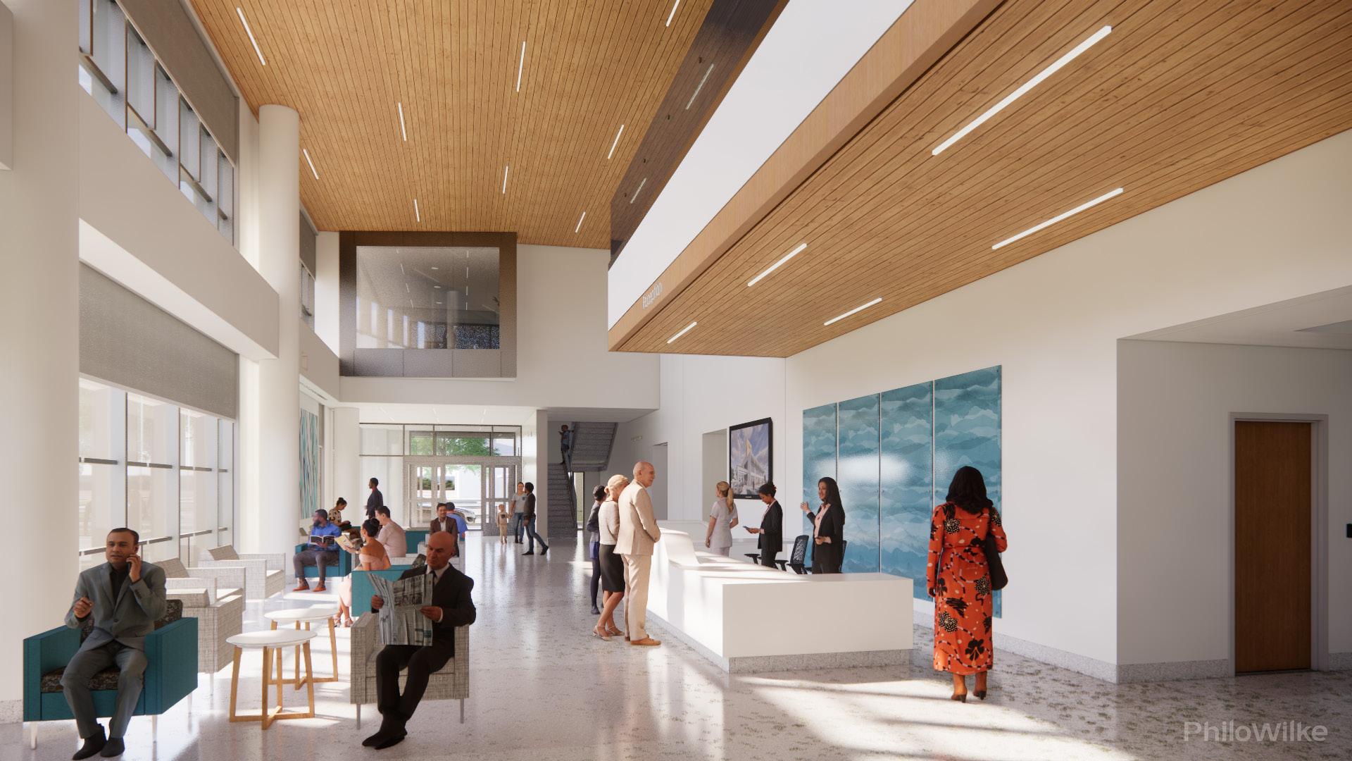
Render | Main Lobby and Level 2 Conference Room Perspective
37
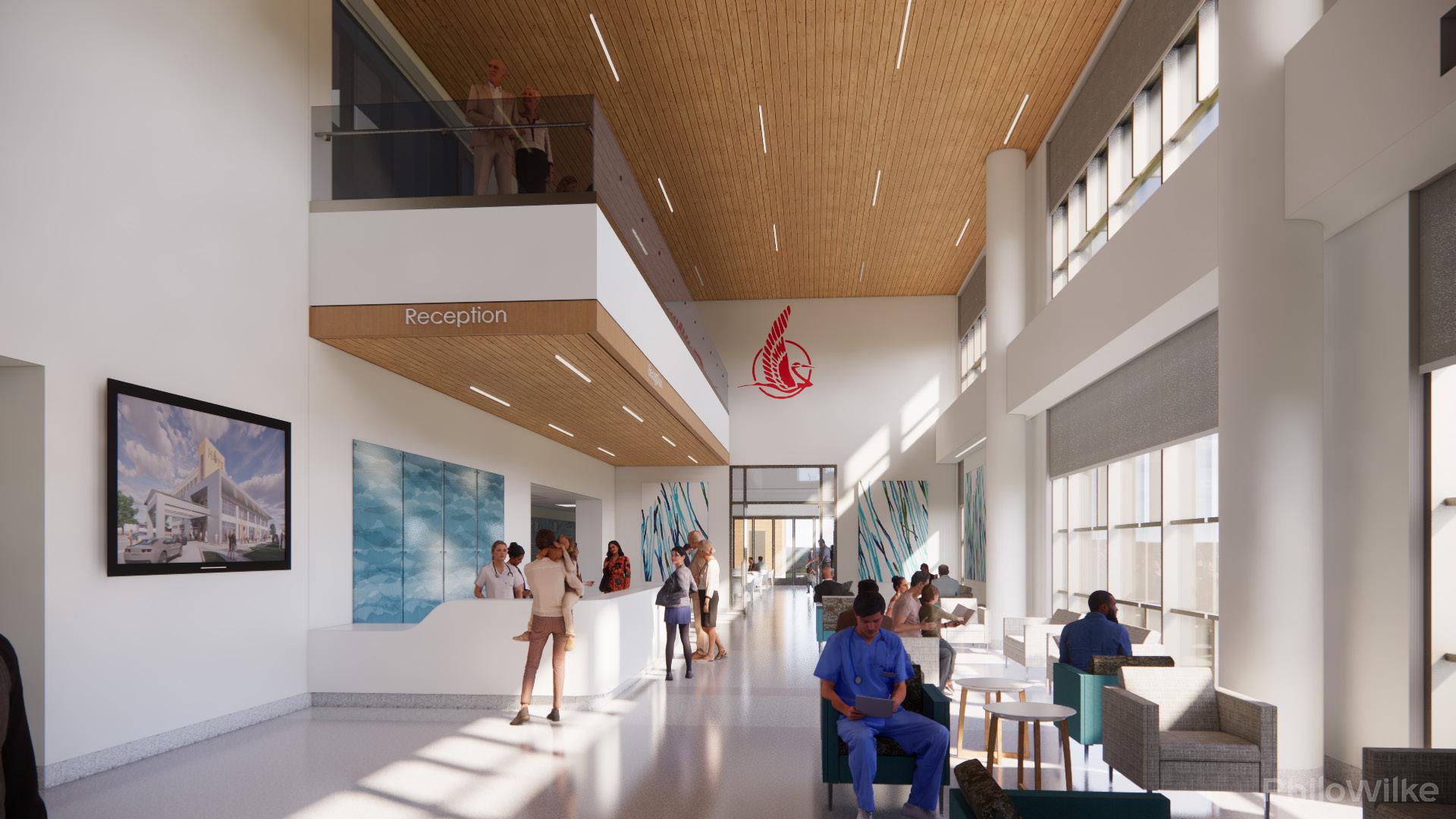
Render | Reception Check-In Desk and Multipurpose Room Perspective
38
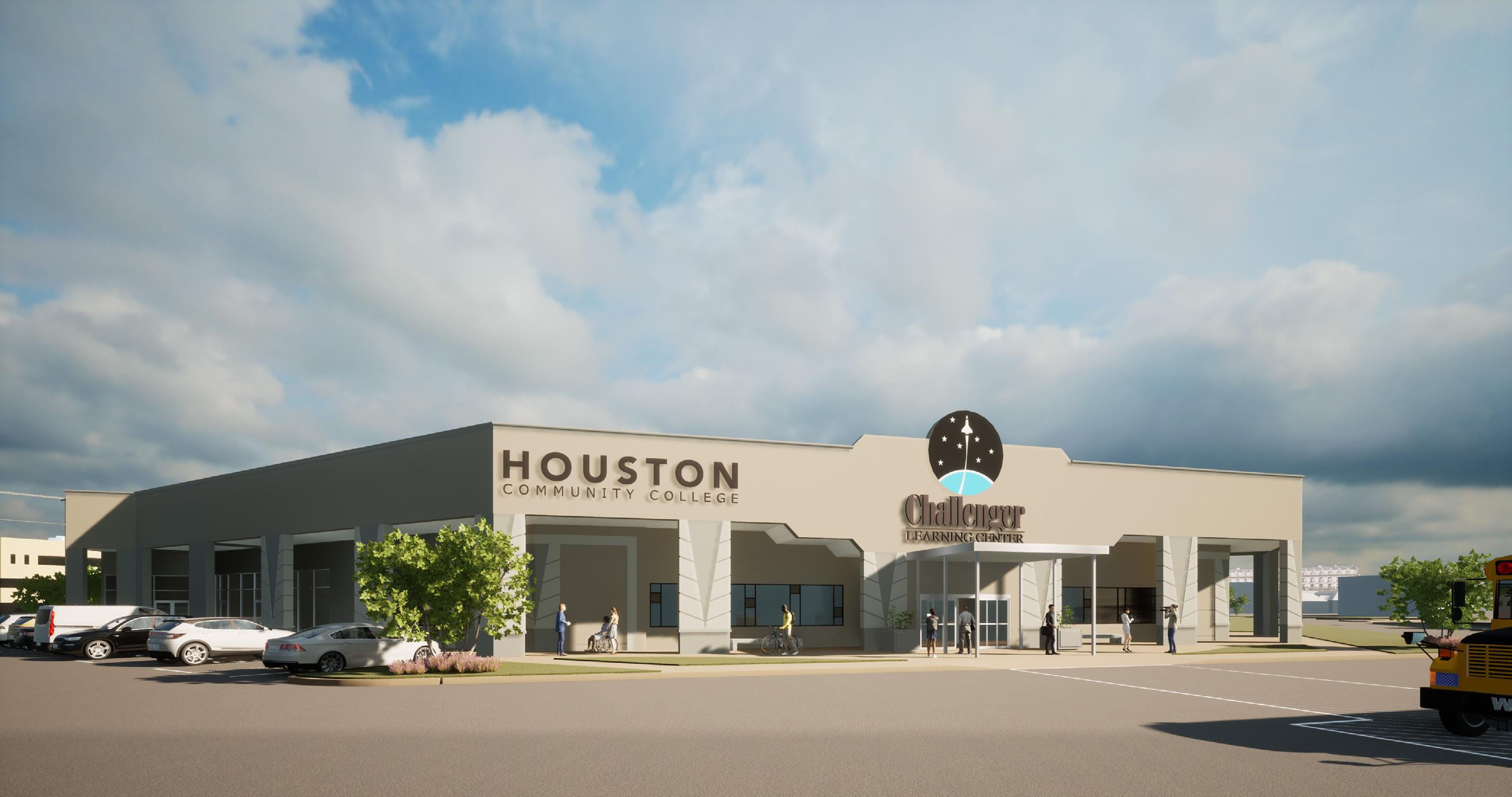
Houston Community College: Challenger Learning Center | 6969 Gulf Freeway, Houston, Texas 77087
Project Information:
Phase I: 19,700 gsf
A. Demolition/ Removal of existing Woodridge Retail Center.
Phase II: 39,700 gsf
B. New HCC Challenger Learning
Project Scope:
The project consists of two phases. The first phase covers the demolition and removal of the existing Woodridge Retail center to create a new view corridor to the HCC Eastside campus. The second phase consist of the demolition, renovation, and build-out the new Challenger Learning Center and various other HCC programs. The site location is adjacent to the main entrance to the HCC campus. Learning Center and various other HCC programs. The site location is adjacent to the main entrance to the HCC campus. build-out the new Challenger Learning Center and various other HCC programs. The site location is adjacent to the main entrance to the HCC campus.
Key Roles:
Architectural designer in charge of various efforts throughout the entire design process, from SD to CA work. Developed schematic designs for floor and ceiling layouts, modeled exterior and interior building components, exterior and interior details, door hardware, finishes, submittals, RFIs, on-site field reports and coordination meetings with oversight from a Project Manager. Exterior work consists of tilt-up exterior insulation finish system wall (EIFS), structural steel and site work. Exterior details included; typical plan details, roof details, material transition details, ext. wall base details, fascia and parapet wall details.
39
Exterior Materials:
Exterior Walls:
Tilt-up exterior insulation system (EIFS)
Canopy: Pre-manufactured aluminum canopy (Avadek system)

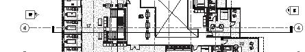
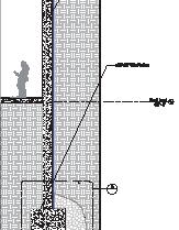
Level 1 Architectural Floor Plan PTO PTO CR CR CR PTO CR CR CR CR F10 210 Corridor Shell 211 F6 213 Elec. Room F11 218 Mission Control F2 219 Office F2 220 Office F2 221 Open Office F3 222 Storage F7 231 Transport Room F13 232 Briefing Room F14 235 Classroom F8 237 IT Room F6 238 Elec. Room F9 239 Mens Restroom F9 240 Womens Restroom F1 247 Welcome Center Entry F4 269 Vestibule Entry F6 272 Jan. F1 290 Challenger Center Pre-Function Area F1 291 Vending Area F12 292 Spacecraft F9 296 Family Restroom F6 298 Elec. Room 3W 3W 11 B B A 3N F6 307 Storage F8 306 IT Room F2 302 Office F14 304 Classroom Storage F6 303 Sprinkler Room F6 305 Water Heater F6 236 Jan. F5 308 Storage F1 248 Reception / Help Desk 2W 1W 2N 1N PWT2 PWT2 7'-113/4" 1'-6" 8'-111/4" 21'-03/4" RT1 RT2 RT1 RT2 RT2 RT3 RT1 RT3 RT3 RT1 RT1 RT2 RT3 RT2 RT2 RT2 RT3 RT1 RT2 RT3 RT3 RT2 RT1 RT1 RT2 RT2 RT2 RT1 RT1 RT1 F2 275 Office RT1 135 135 RT2 RT3 RT2 RT1 45 135 45 RT1 RT1 EQEQEQ 1' 4 3/8" 2' 2" RT1 RT1 RT4 45 135 RT3 RT2 RT1 A-400 A-400 11 135° 135° RT3 RT4 RT1 RT4 RT4 RT4 PT5 1 PT4 PT4 PT4 PT4 PT4 PT4 PT4 PT4 PT4 RT1 RT1 PT4 PT4 PT3 PT4 PT1 PT4 2 3 3 3 Legend -Finish Plan Floor Types RT1 -LVT -Misty Mountain C141 RT2 -LVT -Lava Rock C143 RT3 -LVT -Island Blue C109 RT4 -LVT -Buzzy Yellow C104 Legend -Finish Plan Wall protection. See 15 A-521. PhiloWilke Commission Number Copyright (C) 2023 by PhiloWilke This document and the information part hereof shall be copied, whatsoever except as expressly or corporation receiving this deemed to have agreed to the trust and confidence subject Partnership. Drawing Name Project Issues Revisions Consultants Print Date Time: ELECTRONIC RELEASE NOTICE This electronic drawing file is released by P&W Arc hitects, LLP, who maintain the original file. This electronic drawing file may be used only as background drawing for the specific project for which is released, by the original recipient. The user of this electronic dr awing file agrees to assume all responsibility for any modification to or use of this drawing file that is inconsistent wi th the use specifically permitted. No person may m ake any modification to this electronic drawing file withou the express written permission of P&W Architects, C:\Users\jmontes\Documents\Revit Local\219-128 HCC Challenger(2021)_jmontesKAZNG.rvt 219-128R Finish Plan Houston HCC Challenger Learning Center 6969 Gulf Freeway, Mechanical, Electrical, E&C Inc. 1010 Lamar St., TX 77002 Structural and Civil Dally + Associates, 9800 Richmond Houston, TX 77042 Signage/ Wayfinding Formation 2500 Summer Texas 77007 Landscape Architecture Halff 14800 St. Mary's Houston, TX 77079 PN General Notes -Finish Plan 1. See 4 A-600 for Finish Material Schedule. 1/8" = 1'-0" Finish Plan -Level 1 1 No.Date 101/27/2023Permit 1Coordinate starting and stopping locations with Vendor. 2Existing door to receive custom blackout graphic. 3Custom wall graphic provided by Signage group. Keyed Notes -Finish Plan 1. 2. 40 #. Legend: Rendering Views 3.
Houston Community College: Challenger Learning Center | 6969 Gulf Freeway, Houston, TX 77087
SC SC SC SC SC SC SC SC SC SC SC SC SC SC SC SC SC SC SC A-401 13 A-401 3 EQ EQ EQ EQ EQ 6-0" EQ EQ 6-6" EQ EQ EQ EQ EQ EQ EQ EQ EQEQ EQ EQ EQEQ EQ EQ EQ EQ EQ EQ EQ EQ EQ EQ EQEQ EQ EQ EQEQ EQEQ EQ EQ EQEQ EQEQ EQEQ EQEQ EQEQ EQEQ 10' - 0" 26' 6" EQ 26' 0" 26' 0" EQ 13'0" 13' 0" 13' 0" 13'0" 13' 0" 12'10" 14' 0" 10' 0" 8' 0" 8' 0" 8' 0" 9' 0" 8' - 0" 12' 0" 8' 0" 11' 0" 11' 0" 8' 0" 8' 0" EQ 1 ' -6 " 4' 0"8' 0" 4 A-320 3W 3W 11 11 B B A 3N 3N 1 1 1 1 1 1 1 1 2 1 2 EQ EQ 2 3 2 2 2 4 4 2 2 2 2 2 4 4 4 5 5 5 5 8' 0" 8' 0" 8' - 0" 6 6 6 6 135° 11' 0" 11' 0" 135 135° 135 135 135 135 120TYP 135 ° 5' 0 1/8" 40' - 0" 5' 0" 6' 3 221/256" 2' 11 157/256" 5'0"24' 0" 2 1 6' 0" TYP 3' 4" 2'5" 3' 2" 16' 5" 16' - 5" 16' 5" 14' 9" 13' - 0" 11' 0" 14' 9" 7 7 7 7 7 8 9 8 9 120° 120° 120° 120° 120° 5' 9 1/4"TYP 1' 6 7/8" 15 ° 1' 0" TYP 1 -0" 7' 0 7/8" 6' 11 1/8" 2 2 10 2W 2W 1W 1W 2N 2N 1N 1N EQEQ 8' 6" 11 11 11 11 11 8' 0" 8' 0" 8' 0" A-521 TYP EQ EQ 12 A-521 A-521 3 A-521 A-521 A-521 EQEQ 1' -9" 2 -81/8" 1' -4" 1 ' -4 " 8' 0" 13 A-521 TYP 3 A-521 3 A-521 3 A-521 A-521 A-400 3 A-400 13 1 -6" 1 -6 9' 0" 9' 0" 9' 0" 9' 0" 9' 0" 13 13 13 13 13 13 13 9 9 9 9 9 9 9 9 9 STAT TEX E OF AS OR B ERTCHA RLES B A BB 26431 R EGISTERED ARCHITEC T 11275 S. Sam Houston Suite 200 | Houston, 832.554.1130 | PhiloWilke Commission Number Sheet Number Copyright (C) 2023 by PhiloWilke Partnership. All rights reserved. This document and the information herein the property of PhiloWilke part hereof shall be copied, duplicated, distributed, disclosed or whatsoever except as expressly authorized by PhiloWilke Partnership. or corporation receiving this document, however obtained, shall deemed to have agreed to the forgoing restrictions and that this trust and confidence subject only to the private us expressly authorized Partnership. Drawing Name Project Issues Revisions Consultants Print Date / Time: ELECTRONIC RELEASE NOTICE This electronic drawing file is released by P&W Arc hitects, LLP, who maintain the original file. This drawing file may be used only as background drawing for the specific project for which is released, by the original recipient. The user of this electronic dr awing file agrees to assume all responsibility for any modification to or use of this drawing file that is inconsistent wi th the use specifically permitted. No person may m ake any modification to this electronic drawing file withou the express written permission of P&W Architects, LLP. 1/28/2023 2:46:51 AM C:\Users\jmontes\Documents\Revit Local\219-128 HCC Challenger(2021)_jmontesKAZNG.rvt A-160 219-128R Reflected Ceiling Houston Community HCC Challenger Learning Center 6969 Gulf Freeway, Houston, TX Mechanical, Electrical, Plumbing E&C Inc. 1010 Lamar St., Suite 650 Houston, TX 77002 01/27/2023 Structural and Civil Engineering Dally + Associates, Inc. 9800 Richmond Ave., Suite 460 Houston, TX 77042 Signage/ Wayfinding Formation 2500 Summer St., No.1212 Houston, Texas 77007 Landscape Architecture Halff 14800 St. Mary's Lane, Suite 160 Houston, TX 77079 PN Legend -Reflected Ceiling Plan New partition to structure. See 1 A-520 for partition schedule. General Notes -Reflected Ceiling Plan 1. All new ceilings to be 2' 2' lay-in acoustical ceiling tile at 10'-0" AFF, unless noted otherwise. See Finish Schedule for types, A-600. 2. See Interior Elevations for furr down heights and dimensions. 3. Center all down-lights, sprinkler heads, and wall washers in center of ceiling tile, unless noted otherwise. Keyed Notes -Reflected Ceiling Plan 1Coordinate security camera locations with Owner and Vendor before install, cameras to be Vendor furnished and Vendor installed. 2Coordinate speaker locations with Owner and Vendor before final install, speakers to be Owner furnished and Owner installed. 3Emergency lighting, coordinate with Owner for fina location. 4All ceiling fixtures to have a black finish. 5Provide and install Junction boxes in ceiling as needed. 6Repaint existing plaster ceiling. 7Verify ceiling height in field. 8New plaster ceiling. 9New exterior lay-in ceiling and light fixture, see MEP for more information. 10New roof access ladder. 11Coordinate security camera locations with Owner before install, cameras to be Owner furnished and Owner installed. 12Hexagon ceiling panel, typical, install per manufactures instuctions. 13Add Alternate: Gypsum board and painted plaster inish soffit. Mantain light fixture layout. 1/8" = 1'-0" Reflected Ceiling Plan -Level 1 1 2'x2' ACT Black tiles. Finish type: ACT2 3"x3" Parabolic ceiling grid with 6" edge trim. Finish type: OCP1 Manufactured fiberglass ceiling panels -Hexagon Shape. Finish type: AP3, AP4, AP5 2'x2' ACT White tiles. Finish type: ACT1 No.Date Description 101/27/2023Permit and Construction 2. 3. 1. 41
Level 1 Reflected Ceiling Plan Legend: Rendering Views #.
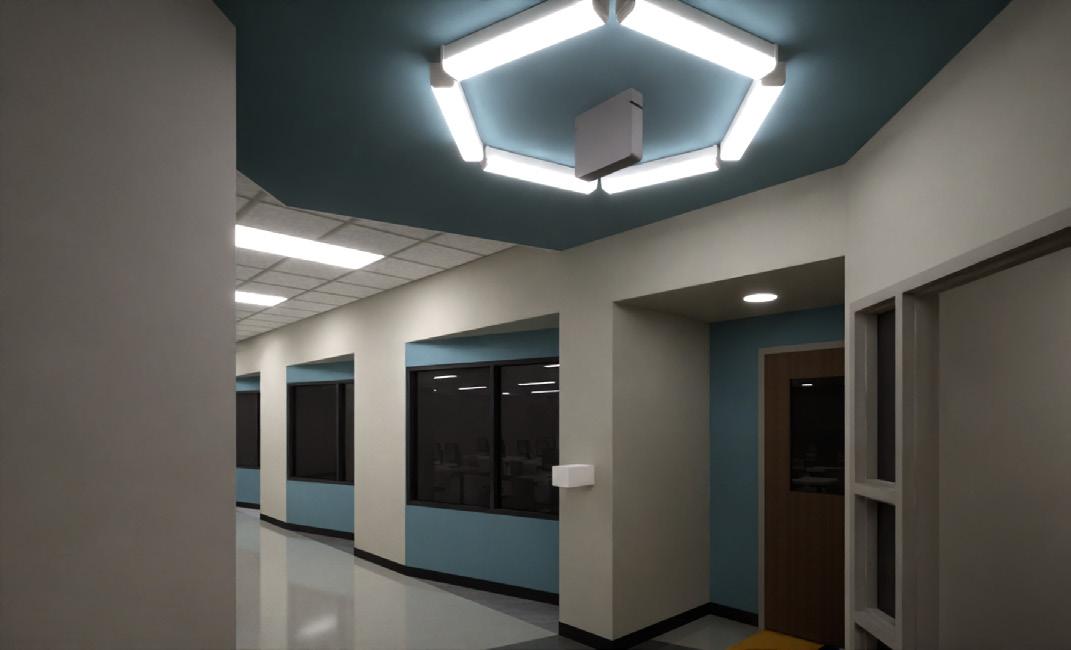
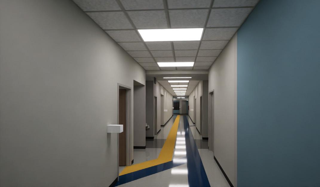

42 Interior Perspective Views and Enlarged Plans | Showcasing Ceiling and Way-finding Floor Finishes 1. | Corridor Intersection Perspective PTO FEC FEC 23 A-400 10 -400 5 A-4 21 A-400 1N 1N 1' 2 7/8" 1' 6" 120 120 120° 120° RT2 RT3 RT3 RT2 RT3 6' 11" C 48 1 21 21' 0 3/4" 16 RT2 RT1 RT1 RT2 1 -6" 120 120 120 60 1 2 0 60 ° 120° RT1 RT2 RT1 120 1 2 0 Align Align 5' 3/8" 11' 0" 12 7 8 20400 25 A400 21 A-561 16 A-561 H1S P1 H1S P1 P2 P2 P2 P2 269a RT4 RT4 RT4 RT4 46 E Q E Q Q 1N 1N AP5 AP4 AP3 AP5 AP5 AP4 AP3 AP4 AP3 30' 0" 1' 6"5' 0 1/4" 17' 1/8" 4' 11 5/8"1' 6" 2 15 16 7 7 / 1 47 1 2 15 1 2 32 11' 0" 11' 11" 11' 8" 11' 5" 11' 2" 11' 5" 11' 2" 11' 5" 11' 2" 11' 5" 11' 0" 18' 0 3/4" A-521 A-521 1 AP3 11' 11" 16 16 16 A-521 16 A-521 2 12' 0" PT2 PT2 PT2 PT2 PT2 PT2 PT2 See RCP 16' 5" Scheduled ceiling Open to above 205 155 16 6 21 A-561 16 A-561 36 20 10 SS1 PL2 SS1 SS16 Scheduled base 18 A-561 366 1See RCP Push botton Scheduled ceiling 16' 5" Open to above PL2 SS1 SS1 PL2 SS1 PL2 PL2 PL2 SS1 25 155 Q E Q E Q PL2 8' 0" 1' 6" 2' 1/2" 2' 1/2" 1' 6" 4" 1" 21 A-561 16 A-561 18 A-561 Access panel Grommet, typical. Coordinate with Owner for final location Scheduled base SS1 1" EQ EQ EQ EQ 40 7 8 Hexagonal ceiling panel Scheduled door and frame PT3 PT1 T o t u t u e Exit sign0 Open to above Scheduled base 3form profile panel 1 65 30 EQ 4 Equal Spaces 16' 0" EQ PT1 307 10 A00s E00 K2S J2S L0C RT2 RT1 RT1 RT3 RT2 RT2 RT1 135 135° 120 EQ EQ 9 14 3 / 8 RT1 RT1 1 -37/8 3/4" 10" 120 1-31/8" 120 120 1 2 0 RT2 RT4 60 RT3 RT4 RT3 RT2 135 135 75 10 5 1 0 5 7 51/2" 1'-75/8" RT1 RT2 RT2 P2 E Q E Q E Q 2135° 1 0 5 A-521 EQ EQ EQ EQ A-521 120 120 1 0 120 1 0 5 1351 1 4 -0" 4 -0" 11 1 2 -9 4 -0 8' 0" 9' 6" 8' 0" EQEQ E Q E Q 135 10' 0" 10' 0" A-521 120 120 1 0 1 0 120° 120 12 -11/2 1 -83/8 1 00 3 / 4 8' 0" 3 A-521 3 A-521 4 -0 PT4 PT4 PT4 PT4 Legend -Finish Plan Floor Types RT1 -LVT -Misty Mountain C141 RT2 -LVT -Lava Rock C143 RT3 -LVT -Island Blue C109 RT4 -LVT -Buzzy Yellow C104 Legend -Finish Plan Floor Types RT1 -LVT -Misty Mountain C141 RT2 -LVT -Lava Rock C143 RT3 -LVT -Island Blue C109 RT4 -LVT -Buzzy Yellow C104 36 S e e R C P 10 10 10 6 Open to above PL2 SS1 SS1 SS1 Scheduled ceiling Scheduled base SS1 3' 1" 1' 0"2' 1" 18 A-561 36 S e e R C Scheduled ceiling Copyright (C) 2023 by PhiloWilke This document and the information part hereof shall be copied, whatsoever except as expressly corporation receiving this deemed to have agreed to trust and confidence subject Partnership. Drawing Name Project Issues Revisions Consultants Print Date Time: hitects, LLP, who maintain the original file. This electronic for the specific project for which released, by the th the use specifically permitted. No person may ake any the express written permission P&W Architects, LLP. K A N G 219-128R Enlarged Elevations Center Corridor Houston HCC Challenger Learning Center 6969 Gulf Freeway, Mechanical, Electrical, E&C Inc. 1010 Lamar TX 77002 Structural and Civil Dally + Associates, 9800 Richmond Houston, TX Signage/ Wayfinding Formation 2500 Summer Texas 77007 Landscape Architecture Halff 14800 St. Mary's Houston, TX 1/4" = 1'-0" Enlarged Plan -Welcome Center Entry 1 1/4" = 1'-0" Enlarged Reflected Ceiling Plan -Welcome Center Entry 3 Note: Refer to Floor Plan for General Notes and Legend. Note: Refer to Floor Plan for General Notes and Legend. 3/8" = 1'-0" Reception/ Help Desk -Frontside Elevation 5 3/8" = 1'-0" Reception/ Help Desk -Backside Elevation 10 0" 21 3/8" 1'-0" Backside of Reception/ Help Desk Elevation 23 1Hexagon ceiling panel, typical, install per manufactures instuctions. 2New manual window shades Keyed Notes -Enlarged Reflected Ceiling Plan 1/4" = 1'-0" Enlarged Plan -Corridor 11 1/4" = 1'-0" Enlarged Reflected Ceiling Plan -Corridor 13 Note: Refer to Floor Plan for General Notes and Legend. Note: Refer to Floor Plan for General Notes and Legend. 3/8" = 1'-0" Reception/ Help Desk -Eastside Elevation 20 0" 25 No.Date 101/27/2023Permit
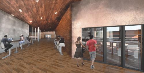
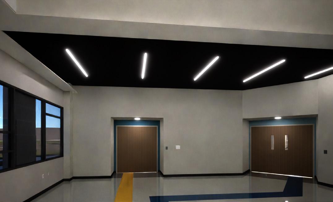
Way-finding Finishes 1. 1. 3. | Challenger Pre-Function Area Perspective | Enlarged Floor and Ceiling Plan at Main Entrance|
2. | Corridor Perspective Showing
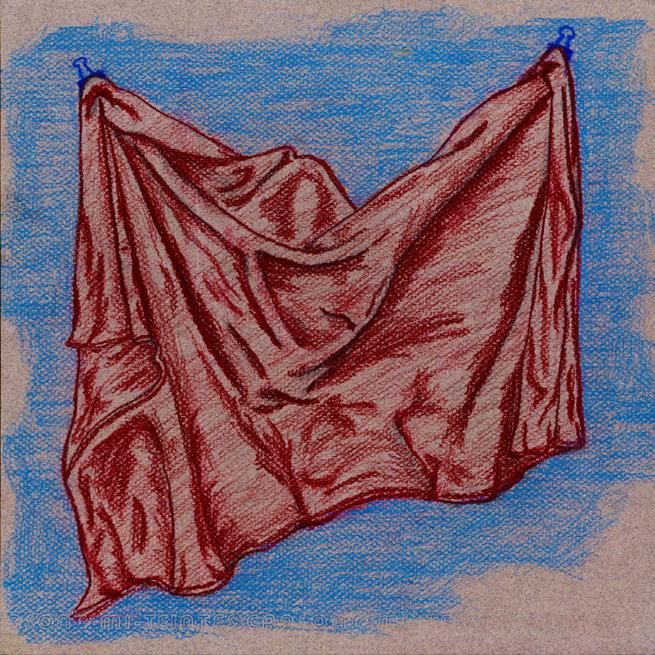


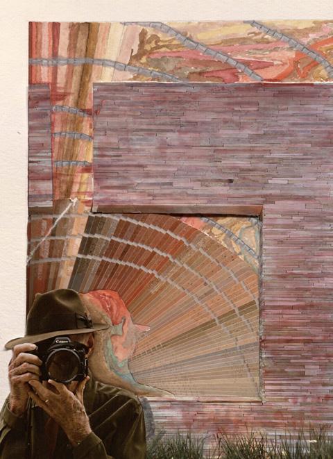


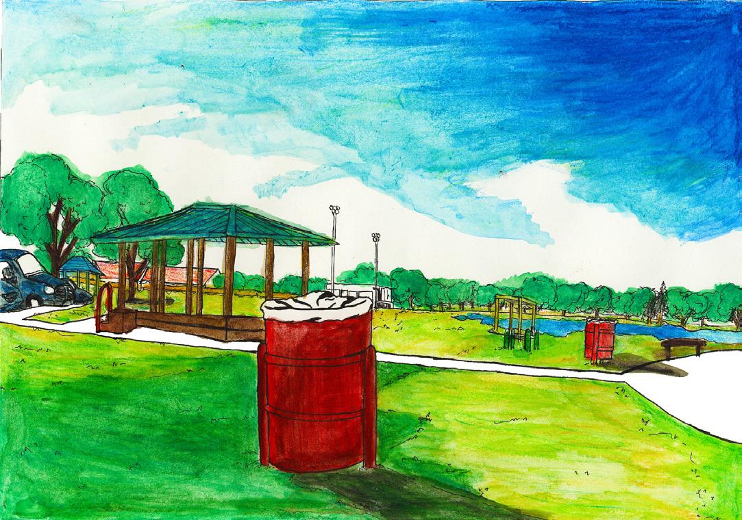
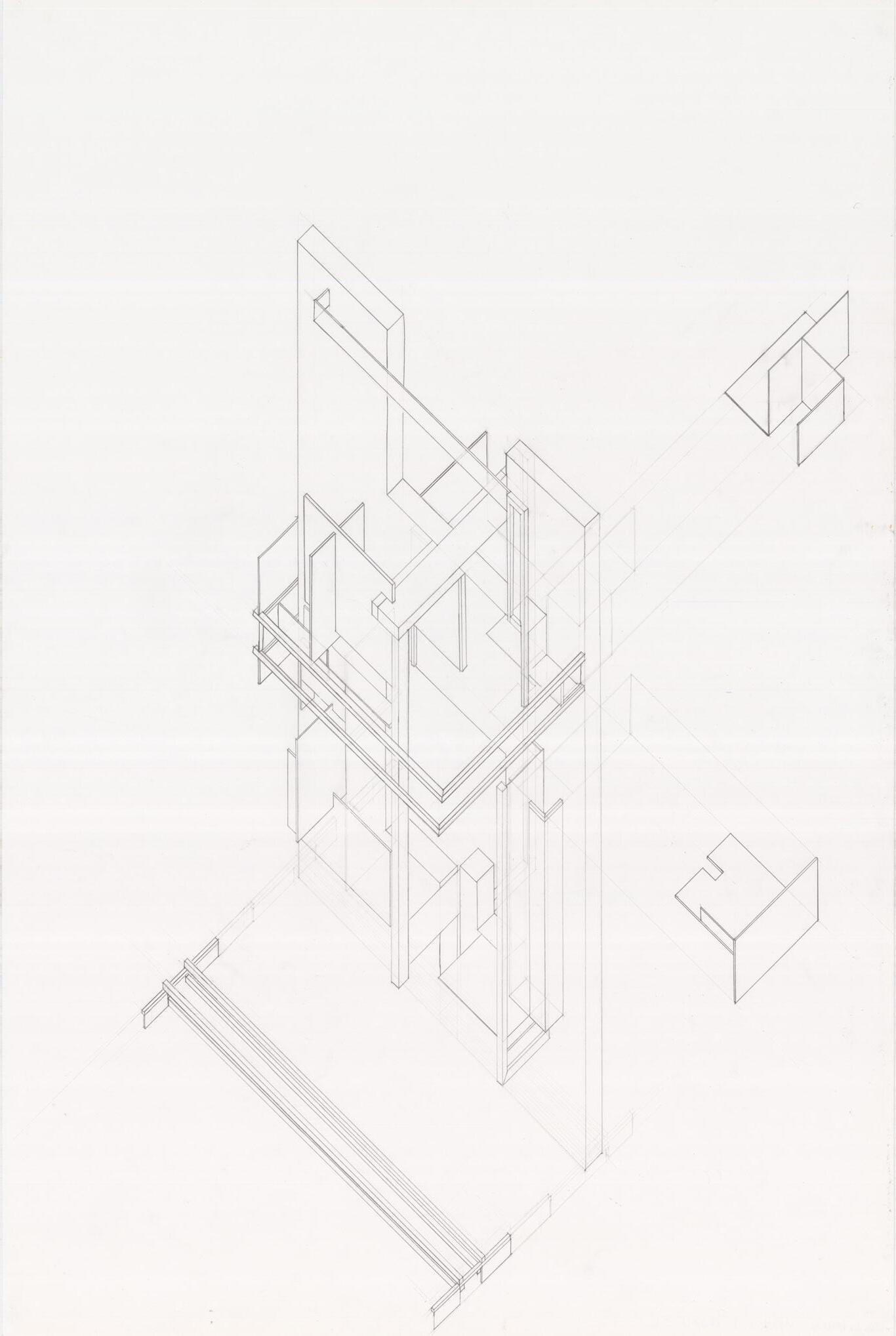
Personal Works | 43


44