Engineering Electromagnetics and Waves 2nd Edition Inan Solutions Manual Visit to Download in Full: https://testbankdeal.com/download/engineering-electromagn etics-and-waves-2nd-edition-inan-solutions-manual/

ThisworkisprotectedbyUnitedStatescopyrightlaws andisprovidedsolelyfortheuseofinstructorsinteaching theircoursesandassessingstudentlearning. Dissemination orsaleofanypartofthiswork(includingontheWorldWideWeb) willdestroytheintegrityoftheworkandisnotpermitted.
(a)ThecutofffrequencyofthedominantTE10 modeinanair-filledhollowWR-10rectangular waveguidewith a = 0 254cmand b = 0 127cmisgivenby
(b)Since a = 2b,thenexthigher-ordermodesareTE11,TE20,andTM11.Thecutofffrequencyof thesethreemodesis
(c)Therefore,thefrequencybandoverwhichonlythedominantTE10 modecanpropagateis fc20 fc10 ≃ 59 1GHz.
Theminimumtunneldimension amin neededforthedominantTE10 modetopropagateat1MHz canbecalculatedas
As longas a > amin = 150m,TE10 willpropagateregardlessofthevalueoftheotherdimension b.Inpractice,sincethereisnotunnelwhichhassuchalargedimension,AMtransmissionthrough atunnelisnotfeasible.
C.3Propagationexperimentinaroadtunnel.
(a)Fortherectangularrailwaytunnelunderconsideration(a = 17mand b = 4.9m),thecutoff frequenciesoftheTE10 andTE01 modesaregivenby
(b)Using (C.17),thelowest-ordermodesthatdonotpropagateatthe100MHzFMfrequencyare TE92 andTM92 sincethecutofffrequencyofthesetwomodesisgivenby
C.4Radio-wavepropagationinrailwaytunnels.
Fortunnel1(a = 8mand b = 4m),thetotalnumberofpropagatingmodesat100MHzis26. ThesemodesareTE10,TE01,(TEandTM)02,(TEandTM)11,(TEandTM)12,(TEandTM)20, (TEandTM)21,(TEandTM)22,(TEandTM)30,(TEandTM)31,(TEandTM)32,(TEandTM)40, (TEandTM)41,and(TEandTM)50.Fortunnel2(a = 6mand b = 4m),thetotalnumberof propagatingmodesat100MHzis18.Unliketunnel1,(TEandTM)32,(TEandTM)40,(TEand TM)41,and(TEandTM)50 modesdonotpropagate.
C.5Rectangularwaveguidemodes.
(a)FortheWR-137rectangularairwaveguide(a = 3 484cm, b = 1 58cm),thecutofffrequencies ofthefourlowest-ordermodesTE10,TE20 (andTM20),TE01,andTE11 (andTM11)arerespectively calculatedfrom(C.17)as f
(b)ForthedominantTE10 mode,thephasevelocity vp andtheguidewavelength λ atthetwoend frequencies(i.e.,5.85GHzand8.20GHz)ofthespecifiedfrequencyrangecanbecalculatedusing (C.20)and(C.21)as
ThisworkisprotectedbyUnitedStatescopyrightlaws andisprovidedsolelyfortheuseofinstructorsinteaching theircoursesandassessingstudentlearning. Dissemination orsaleofanypartofthiswork(includingontheWorldWideWeb) willdestroytheintegrityoftheworkandisnotpermitted.
(a)ThecutofffrequencyofthedominantTE10 modeintheWR-137rectangularairwaveguide (a = 3 484cm, b = 1 58cm)canbecalculatedfrom(C.17)as
(b)Repeatingthesamecalculationsasinpart(a)at7GHz,wehave
ThisworkisprotectedbyUnitedStatescopyrightlaws andisprovidedsolelyfortheuseofinstructorsinteaching theircoursesandassessingstudentlearning. Dissemination orsaleofanypartofthiswork(includingontheWorldWideWeb) willdestroytheintegrityoftheworkandisnotpermitted.
10
(a)Using(C.21),theguidewavelengthofthedominantTE10 modepropagatinginarectangular airwaveguidewith a = 2b = 7 214cmcanbewrittenas
used.Notethattheexpression foundfor λ10 aboveisonlyvalidfor f >∼ 2 08GHz(i.e.,propagatingcase).Thisexpression(i.e., λ10)isplottedasafunctionoffrequency f asshowninFigureC.1.
(b)Ifthesamewaveguideisfilledwithwater(assume ϵr ≃ 81),then, fc10 ≃ 2 08/√81 ≃ 0 231 GHz.Therefore, theguidewavelengthforthiscaseisgivenby
whichisvalidfor f >∼ 0 231GHz.ThisexpressionisplottedinFigureC.1asafunctionofthe frequency f
(c)ForthepropagatingTE20 modeintheairwaveguideofpart(a),the λ20 expressionisthesameas the λ10 expressionexcept2.08shouldbereplacedby4.16(i.e., fc20 = 2fc10).Thisexpressionisvalid for f >∼ 4.16GHzandisplottedasafunctionof f inFigureC.1.ForthepropagatingTE20 mode inthewater-filledwaveguideofpart(b), λ20 expressionisthesameasthe λ10 expressionfound inpart(b)exceptthat0.231shouldbereplacedby0.462.Thisexpressionisvalidfor f >∼ 0 462 GHzandisplottedinFigureC.1.
C.8Rectangularwaveguidemodes.
(a)FortheWR-42rectangularairwaveguide(a = 1 067cm, b = 0 432cm),thecutofffrequencies oftheTE10,TE01,TE11,TE
NotethatallthesemodesexcepttheTE02 modearepropagatingat40GHz.Thepropagation constantsandthewaveimpedancesofthesemodescanbecalculatedusing(C.18)and(C.19)as
ThisworkisprotectedbyUnitedStatescopyrightlaws andisprovidedsolelyfortheuseofinstructorsinteaching theircoursesandassessingstudentlearning. Dissemination orsaleofanypartofthiswork(includingontheWorldWideWeb) willdestroytheintegrityoftheworkandisnotpermitted.
(b)For theTE10 mode,wehavefrom(C.20)and(C.21)
C.9Dielectric-filledwaveguide.
(a)FortheWR-22rectangularwaveguide(a = 0 569cm, b = 0 284cm)filledwithadielectric materialhaving ϵr,thephaseshiftexperiencedbythedominantpropagatingTE10 modeovera lengthof1cmat13.2GHzcanbewrittenas
But, from(C.18),wehave
30√
/(2 × 0 569) inGHz.Substituting,wehave
fromwhich solving,wefind
(b)Notethat fc10 ≃ 8 78GHz.Since a ≃ 2b,thenexthighermodeisTE20 (orTE11)whichhasa cutofffrequency fc20 ≃ 17 6GHz > 13 2GHz.Therefore,nomodeotherthanTE10 propagatesat 13.2GHz.
(c)Ifthedielectricfillingisreplacedwithair,then, fc10 ≃ 3 × 10¹⁰/(2 × 0.569) ≃ 26.4GHz > 13.2GHz.Therefore,inthiscase,nopropagationoccursdowntheguide.
(a)FortheWR-1500airwaveguide(a = 2b = 38.1cm),thecutoffwavelengthofthedominant TE10 modecanbefoundfrom(C.19)as λc10 = 2a = 76.2cm.
(b)Thephasevelocity,guidewavelength,andthewaveimpedanceforthedominantTE10 modeat λair = 0 8λc10 canbecalculatedfrom(C.20),(C.21)and(C.28)as
(c)At λair = 40 cm,onlythedominantTE10 modepropagatessincethenexthighermodeTE20 (orTE11)has λc20 = λc10/2 = 38.1cm < 40cm.
(d)At λair = 30cm,thepropagatingmodesareTE10,TE20 andTM20 (λc20 = 38.1cm),TE01 (λc01 = 38.1cm),andTE11 andTM11 (λ
.1cm).
ThisworkisprotectedbyUnitedStatescopyrightlaws andisprovidedsolelyfortheuseofinstructorsinteaching theircoursesandassessingstudentlearning. Dissemination orsaleofanypartofthiswork(includingontheWorldWideWeb) willdestroytheintegrityoftheworkandisnotpermitted.
(a)FortheWR-1500polyethylene-filledwaveguide(a = 2b = 38 1cm),thecutoffwavelengthof thedominantTE10 modecanbefoundfrom(C.19)as λc10 = 2a = 76 2cm.
(b)Thephasevelocity,guidewavelength,andthewaveimpedanceforthedominantTE10 modeat λair = 0 8λc10 canbecalculatedfrom(C.20),(C.21)and(C.28)as
(c)At
(d)At λair = 30cm,thepropagatingmodesareTE10,TE
(
c20 = 38 1cm),TE01 (λc01 = 38 1cm),andTE11 andTM11 (λc11 = 2ab/
+
34 1cm).
(a)Sincethe y componentoftheelectricfieldphasorisorientedintheguidingdirectionofthe rectangularwaveguide,thismodecanneitherbeTEMorTEmn,therefore,itmustbeaTMmn mode. Usingthewaveguidedimensions a = 4cm(inthe z direction)and b = 2cm(inthe x direction) andcomparingthe Ey expressiongivenintheproblemwiththe Ez expressiongivenby(C.15),we have
ThisworkisprotectedbyUnitedStatescopyrightlaws andisprovidedsolelyfortheuseofinstructorsinteaching theircoursesandassessingstudentlearning. Dissemination orsaleofanypartofthiswork(includingontheWorldWideWeb) willdestroytheintegrityoftheworkandisnotpermitted.
Therefore,this isaTM11 mode.Itisanevanescentwavebecauseoftheattenuationterm e 41πy .
(b)Using(C.16),theoperatingfrequencycanbeevaluatedfromtheattenuationconstant α11 as
(c)Notethatthecutofffrequenciesofthetwolower-orderTE10 andTE01 modesare
C.13Alargewaveguidefordeephyperthermia.
(a)Forthelargewaveguide(a = 6m, b = 30cm)designedtobeusedfordeephyperthermia,since a >> b,thecutofffrequencyofthelower-ordermodesisdeterminedbythelargerdimension a. Assumingthewaveguidetobeair-filled,thecutofffrequenciesofthefivelowest-orderTEm0 are givenby
(where vp = c ≃ 3 × 10⁸ m-s 1)yielding fcTE10 = 25MHz, fcTE20 = 50 MHz, fcTE30 = 75MHz, fcTE40 = 100MHz,and fcTE50 = 125MHzrespectively.Notethatthecutofffrequenciesofthe TMm0 modeswith m = 2, 3, 4, 5areexactlythesameasthecutofffrequenciesoftheirTEm0 mode counterpartswith m = 2, 3, 4, 5.
(b)Ifthewaveguideisfilledwithwater(assume ϵr ≃ 81),then vp = c/√ϵr = c/9.Therefore, The cutofffrequenciesforthewater-filledwaveguideare1/9timesthecutofffrequenciesoftheairfilledwaveguideyieldingthecutofffrequenciesforthefivelowest-orderTEm0 modesas fcTE10 ≃ 2.78MHz, fcTE20 ≃ 5.56MHz, fcTE30 ≃ 8.33MHz, fcTE40 ≃ 11.1MHz,and fcTE50 ≃ 13.9MHz respectively.
(c)Forthewater-filledwaveguidewithnewdimensions a = 70cmand b = 30cm,thecutoff frequenciesofthefivelowest-orderTEmn modesarefoundtobe f
,TM30,andTM11 modeshaveexactlythesamecutofffrequenciesastheirTEmn counterparts.
(a)Forthesquareairwaveguide(a = b = 3cm)at8GHz,thecutofffrequenciesofallthe propagatingTEmn andTMmn modesat8GHzaregivenby
where vp = c ≃ 3 × 10⁸ m-s 1 is used.Notethatallofthesevaluescutofffrequencyvaluesare < 8GHzandthereforethesemodes(i.e.,TE10,TE01,TE11,andTM11)aretheonlypropagating modesat8GHz.
(b)Ifthesamesquarewaveguideisfilledwithpolystyrene(ϵr ≃ 2.56),then,werecalculatethe cutofffrequenciesofthepropagatingmodesas
waveguideat8GHz.
ThisworkisprotectedbyUnitedStatescopyrightlaws andisprovidedsolelyfortheuseofinstructorsinteaching theircoursesandassessingstudentlearning. Dissemination orsaleofanypartofthiswork(includingontheWorldWideWeb) willdestroytheintegrityoftheworkandisnotpermitted.
(a)Forthespeciallydesignednonstandardair-filledwaveguidewithdimensions a = 19cmand
b = 14cm,theonlymodethatisexcitedat900MHzisthedominantTE10 modewhichhasa cutofffrequency fc10 ≃ 3 × 10¹⁰/[2(19)] ≃ 789.5MHz < 900MHz.
(b)ThecutofffrequencyofthenexthighermodewhichistheTE01 modeisgivenby fc01 ≃ 3 × 10¹⁰/[2(14)] ≃ 1 07GHz,so,thefrequencyrangeoverwhichonlythedominantmodecan propagatecanbefoundas fc01 fc10 ≃ 282MHz.
(c)IftheTE01 modedoesnotexist,then,thecutofffrequencyofthenexthighermodewhichisthe TE11 mode(andtheTM11 mode)iscalculatedas
Therefore,thefrequencyrangeinwhichonlythedominantmodepropagates(ignoringtheexistence oftheweakTE01 mode)isgivenby
(a)FortheW-bandrectangularairwaveguidewithdimensions a = 2 54mmand b = 0 7mm,the cutofffrequenciesofthethreelowest-ordermodesaregivenby
(b)ThefrequencyrangeoverwhichonlythedominantTE
ThisworkisprotectedbyUnitedStatescopyrightlaws andisprovidedsolelyfortheuseofinstructorsinteaching theircoursesandassessingstudentlearning. Dissemination orsaleofanypartofthiswork(includingontheWorldWideWeb) willdestroytheintegrityoftheworkandisnotpermitted.
C.17TE10 modeinarectangularwaveguide.
(b)Note thatthetime-averagepowercarriedbythedominantTE10 modealongtherectangular waveguideisgivenby
0.1083m,and b ≃ 0.054165malongwiththevalueof C intheaboveexpression,wefind Pav ≃ 964 4W.
C.18Dominantmodeinarectangularwaveguidedesign.
(a)Thethreedesigncriteriafortherectangularwaveguideunderconsiderationare
1 25fc10 ≤ 15GHz
1 25 × 18 5GHz ≤ fcnexthigher and Pav ofthedominantTE10 modeistobemaximized.Assuming a = 2b andusing fc10 = c/(2a) where c ≃ 3 × 1010 cm-s 1,thefirstdesigncriteriayields amin = 1.25cm.Next,using fcnexthigher = fc20 = 2fc10 = c/a,theseconddesigncriteriayields amax ≃ 1.2973cm.Therefore, thelongertransversedimension a mustlieintherange1.25 ≤ a ≤∼ 1.2973cm.However,since thethirddesigncriteriaistomaximizepowertransfer,wechoosethelargestpossiblevalueof a = amax ≃ 1.2973cm.Forthisvalueof a,thecutofffrequencyofthedominantTE10 modecan becalculatedas fc10 ≃ 3 × 10¹⁰/(2 × 1 2973) ≃ 11 56GHz.
(b)ThecutofffrequencyofthenexthigherTE20 (orTE01)modeis fc20 = 2fc10 ≃ 23 13GHz > 22GHz.
(c)Using(C.30)at15GHz,thetime-averagepowercarriedbythedominantTE10 modewithpeak electricfieldvalue E0 = 1.5 × 10⁶ V-m 1 canbecalculatedas
C.19Rectangularwaveguidedesign.
(a)Usingthecutofffrequencyofthedominantmode,wehave
TomaximizethefrequencyrangeoverwhichnoothermodebutthedominantTE10 modecan propagate,wechoose
(b)ThenexthighermodesareTE01 andTE20 (andTM20).Forthesemodes,thecutofffrequency is5.16GHz.
ThisworkisprotectedbyUnitedStatescopyrightlaws andisprovidedsolelyfortheuseofinstructorsinteaching theircoursesandassessingstudentlearning. Dissemination orsaleofanypartofthiswork(includingontheWorldWideWeb) willdestroytheintegrityoftheworkandisnotpermitted.
(c)Using(C.25), thepeakelectricfieldvalueintheairwaveguidewith a ≃ 5 814cmat4GHz canbewrittenas
fromwhich wecansolveforthemaximumpeakvalue C oftheaxialcomponentofthemagnetic fieldcorrespondingtothebreakdownstrengthofairwithasafetyfactorof2atsealevelas
2 57kA-m 1.Substitutingthisvalue,themaximumtime-averagepowercarryingcapacityofthe waveguidecanbecalculatedas
C.20 Maximumfieldinarectangularwaveguide.
(a)FortheWR-650rectangularairwaveguide(a = 2b = 16 51cm),thecutofffrequencyofthe dominantTE10 modeisgivenby
Therefore, sincethenexthigherTE20 mode(ortheTE01 mode)hasacutofffrequencyof fc20 = 2fc10 ≃ 1 82GHz > 1 1GHz,onlythedominantTE10 modepropagatesontheWR-650waveguide at1.1GHz.FortheWR-975rectangularairwaveguide(a = 2b = 24 765cm),thecutofffrequency ofthedominantTE10 modeisgivenby
Therefore, sincethenexthigherTE20 mode(ortheTE01 mode)hasacutofffrequencyof fc20 = 2fc10 ≃ 1 21GHz > 1 1GHz,similartothecaseofWR-650waveguide,onlythedominantTE10 modepropagatesontheWR-975waveguideat1.1GHz.
(b)FortheWR-650waveguide,thepeakelectricfieldcorrespondingtothepeakpowerof2GW canbecalculatedfrom
ThisworkisprotectedbyUnitedStatescopyrightlaws andisprovidedsolelyfortheuseofinstructorsinteaching theircoursesandassessingstudentlearning.
orsaleofanypartofthiswork(includingontheWorldWideWeb) willdestroytheintegrityoftheworkandisnotpermitted.
(c)WR-975 waveguideshouldbechosenforhigherpowercapacitysinceithasawidercrosssectionalareaandasaresultcanhandlemorepowerthantheWR-650waveguidebeforedielectric breakdownoccurs.
C.21Powercapacityofarectangularwaveguide.
(a)FortheWR-284rectangularairwaveguide(a = 7 214cm, b = 3 404cm),thecutofffrequency ofthedominantTE10 modeisgivenby fc10 = c/(2a) ≃ 2 079GHz.>From(C.25),themaximum allowablepeakelectricfieldcanbewrittenas
Substituting f = 2 45GHz, a = 7 214cm,and µ0 = 4π × 10 7 H-m 1,wecansolveforthe allowablepeakvalueoftheaxialmagneticfieldcomponentas C ≃ 3, 377A-m 1.Thephase constant β10 correspondingtothedominantTE10 modecanbefoundfrom(C.25)as
Usingthe valuesof C and β10,wecancalculatethemaximumtime-averagepowerthatcanbe carriedbythedominantTE10 modealongtheWR-284rectangularairwaveguideas
(b)Repeatingthesamecalculationsinpart(a)fortheWR-430rectangularairwaveguide(
parts(a)and(b),onecanconcludethatthemaximumpowercapacityoftheWR-430waveguideis about4timeshigherthanthemaximumpowercapacityoftheWR-284waveguide.
C.22TE11 modeinarectangularwaveguide.
(a)Comparingthegiven Hz expressionforTE11 with(C.23),thewaveguidedimensioncanbe foundas
Theoperating frequencycanbeobtainedusingthephaseconstantgivenby(C.18)as
ThisworkisprotectedbyUnitedStatescopyrightlaws andisprovidedsolelyfortheuseofinstructorsinteaching theircoursesandassessingstudentlearning. Dissemination orsaleofanypartofthiswork(includingontheWorldWideWeb) willdestroytheintegrityoftheworkandisnotpermitted.
(b)Usingthefieldcomponentsgivenin(C.23),thetime-averagePoyntingvectorfortheTE11 mode canbewrittenas
(c)TheothernonzerocomponentsoftheTE
(d)Usingthebreakdownvalueoftheelectricfield,wecancalculatethenewvalueof C as
The maximumtime-averagepowercorrespondingtothisnewvalueof C isfoundtobe
kW.
C.23NoTM01 orTM10 modesinarectangularwaveguide.
Tohaveoneoftheindiceszeromeansthatthefieldquantitydoesnotvaryinthecorresponding directionacrossthecrosssectionoftheguide.ForaTMmode,themagneticfieldlinesareby definitionentirelytransverse,andbothcomponents(*x and *y)mustbenonzerosincethemagnetic fieldlinesmustalwayscloseonthemselves.However,eachcomponentmustthenvaryinitsown direction(i.e., *x mustvaryin x and *y mustvaryin y)inordertonotbeperpendiculartothe wallsasrequiredbytheboundarycondition.Thus,neither m nor n canbezero.
ThisworkisprotectedbyUnitedStatescopyrightlaws andisprovidedsolelyfortheuseofinstructorsinteaching theircoursesandassessingstudentlearning. Dissemination orsaleofanypartofthiswork(includingontheWorldWideWeb) willdestroytheintegrityoftheworkandisnotpermitted.
C.24No TEMwaveinasingle-conductorwaveguide.
HavingaTEMmodewouldmeanthatthereisneitheran %z or *z component.However,since themagneticfieldlinesmustalwayscloseonthemselves, *x and *y mustbothbenonzero,and theirclosedloopsmustthengenerate(through(7.21c))displacementcurrent(i.e., ∂
)inthe z direction,contradictingouroriginalpremiseofno %z component.
C.25Powercapacityofarectangularwaveguide.
(a)Usingthetime-averagepowerexpressionofthedominantTE10 modeas
/∂
wherethe cutofffrequencyofthedominantmodeisreplacedby
wesolvefortheamplitude C oftheaxialmagneticfieldcomponenttobe
(b) Sincepowerisproportionaltothesquareofthepeakvalueoftheelectricfield,themaximum time-averagepowercarryingcapacityoftheTE10 modeunderthe |Ey|max = 1500kV-m 1 criteria canbecalculatedfrombasicratioas
C.26Cutoff frequencyforacircularwaveguide.
11 modeina7cmdiametercircularairwaveguideisgiven by
∼2.51GHz.Therefore,nowavescanbetransmittedalongthiswaveguidebelow ∼ 2 51GHz.
C.27TE11 modeinacircularwaveguide.
(a)UsingthecutofffrequencyofthedominantTE11 modeas
wefind thesmallestdiameterofthecircularairwaveguidethatwillallowthepropagationofthe dominantmodeat40MHztobe2amin ≃ 4.396m.
ThisworkisprotectedbyUnitedStatescopyrightlaws andisprovidedsolelyfortheuseofinstructorsinteaching theircoursesandassessingstudentlearning. Dissemination orsaleofanypartofthiswork(includingontheWorldWideWeb) willdestroytheintegrityoftheworkandisnotpermitted.
(b)Repeating part(a)for40GHzyields2amin ≃ 4 396mm.Inotherwords,whenthefrequency increasesbyafactorof1000,thediameterofthewaveguideisreducedbyafactorof1000forthe samemodeoperationtohold.
C.28Square-to-circularwaveguide.
(a)Forthesquareairwaveguidewithdimensions a = b = 2.4cm,thecutofffrequencyofthe dominantTE10 andTE01 modesisgivenby
Therefore, onlythedominantTE10 andTE01 modescanpropagateat7GHz.
(b)Conservingtheperimeter,wehave2πa = 4 × 2 4cmfromwhichwefindtheradius a ofthe circularairwaveguideas a ≃ 1 528cm.Usingthisvalue,thecutofffrequencyofthedominant TE11 modeisgivenby
The cutofffrequencyofthenexthigherTM01 modecanbecalculatedas
Therefore,onlythedominantTE11 modepropagatesat7GHz.
(a)Foranair-filledwaveguide,theminimumdiameter dmin requiredtoallowanypropagationat
air = 1mcanbecalculatedfromthecutoffwavelengthofthelowest-orderTE11 modeas
Similarly,forawater-filledwaveguide(ϵr ≃ 81),wehave
(b)Repeatingpart(a)foranair-filledwaveguideat λair = 15cm,wefind dmin ≃ 8 79cm.
(c)Using2a = 12 7cmand λair = 15cm,thecutoffwavelengthisgivenby
=
) ≤ 2 660.Therefore,usingTablesC.2andC.3,onlyTE11 andTM01 modes propagateat
resultingin (
ThisworkisprotectedbyUnitedStatescopyrightlaws andisprovidedsolelyfortheuseofinstructorsinteaching theircoursesandassessingstudentlearning. Dissemination orsaleofanypartofthiswork(includingontheWorldWideWeb) willdestroytheintegrityoftheworkandisnotpermitted.
Fora λair = 50cmsignalsource, f = c/λair ≃ 600MHz.ProfessorBarrowusedahollow cylindricalwaveguidewithradius a = 2.25cm.Thecutofffrequencyofthelowest-orderTE11 modeforthiswaveguideisgivenby
Therefore,theexperimentwasunsuccessfulbecausenopropagationmodeexistsonthiswaveguide at600MHz.
(b) λair = 40cm → f ≃ 750MHz.Using a = 22 85cm,thecutofffrequencyofthelowest-order TE11 modeinthisguideisgivenby
Therefore,TE11 modepropagatesat750MHzandasaresult,theexperimentinthiscasewas successful.DidProfessorBarrowobserveanyotherpropagatingmodesinthisexperiment?
(a)EquatingthecutofffrequencyofamodetothehighestAMfrequency,wehave
Therefore,AM radiowavesdonotpropagatealongthe7.6mdiametertunnel.
(b)Using108MHzandfollowingasimilarapproachasinpart(a),wefind (snl or (tnl) ≃ 8.595. Therefore,usingasourcesuchasBeattie(seefootnote22inChapter5),themaximumnumberof propagatingmodesat108MHzFMfrequencyisfoundtobe21.
(c)Followingasimilarapproachasinpart(a),again,wefindoutthatAMdoesnotpropagate. Using108MHz,wefind (snl or (tnl) ≃ 5 429andasaresult,maximumof9differentmodescan propagate.
(a)Comparingthe Hϕ expressionwith(C.48)and(C.50),weconcludethatthismodeisaTMnl modeandthat n = 0.Tofindthevalueof l ,weuse
Comparingwith therootsprovidedinTableC.2,thismodeisidentifiedastheTM02 mode.This isapropagatingmode,asisevidentfromthe ej48πz term.
(b)Using(C.46),wecanwrite
ThisworkisprotectedbyUnitedStatescopyrightlaws andisprovidedsolelyfortheuseofinstructorsinteaching theircoursesandassessingstudentlearning. Dissemination orsaleofanypartofthiswork(includingontheWorldWideWeb) willdestroytheintegrityoftheworkandisnotpermitted.
(c)From(C.48), wehave
Therefore,the othernonzerofieldcomponentsofthisTM02 modecanbewrittenas
(d)Fromthecutofffrequencyexpressionwehave
UsingTablesC.2andC.3,thetotalnumberofpropagatingmodespossibleat ∼9.760GHzisfound tobe18(i.e.,7TMnl and11TEnl)modes.
C.33Unknowncircularwaveguidemode.
(a)TofindtheunknownTEnl modepropagatinginthecircularairwaveguidewith a = 3.5cm,we use(C.50)whichyields n = 3and snl/(0.035m)= 120 → s3l ≃ 4.200andfromTableC.3,we
l = 1.Therefore,thisistheTE31 mode.Itisapropagatingmodebecauseofthe e j116 9z terminthe Hz phasorexpression.
(b)Theoperationfrequencycanbecalculatedfromthephaseconstantexpressiongivenby
f
(c)Tofindthehighest-orderpropagatingmodeat ∼ 8GHz,wehave
Therefore,the highest-orderpropagatingmodeat ∼ 8GHzistheTM02 mode.
(d)FortheTM02 modepropagatinginthe z direction,
5201fromTable C.2,the
ThisworkisprotectedbyUnitedStatescopyrightlaws andisprovidedsolelyfortheuseofinstructorsinteaching theircoursesandassessingstudentlearning.
C.34Smallestcircularwaveguidedimension.
(a)FromTableC.2,thecutofffrequencyoftheTM 21modeinacircularair-filledwaveguideis givenby
(b)ThecutofffrequencyoftheTM12
C.35Circularwaveguidemodes.
(a)SincetheWC-80(a = 1.012cm)circularairwaveguide(i.e., vp = c ≃ 3 × 10⁸ m-s 1)is operatedat16GHz,thecutofffrequenciesofallthepropagatingmodesmustsatisfytheinequality
≃ 3 054),wefindthatthe onlymodesthatwillpropagateinthiswaveguideat16GHzareTE11,TM01 andTE21 respectively.
(b)Thecutofffrequenciesofthepropagatingmodesaregivenby
Usingthese values,thephasevelocity,guidewavelength,andthewaveimpedanceofthesepropagatingmodesat16GHzcanbecalculatedas
andisprovidedsolelyfortheuseofinstructorsinteaching theircoursesandassessingstudentlearning.
C.36Low-lossTE01 modeinacircularwaveguide.
(a)Foranair-filledcircularwaveguidewithradius a = 5cm,thecutofffrequencyofthelow-loss TE01 modeisgivenby
(b)If thesamecircularwaveguideisfilledwithwater(assume ϵr ≃ 81),then,thenewcutoff
01 modeis
C.37Low-lossTE01 modeinahighlyovermodedwaveguide.
(a)Usingthe Eϕ expressionin(C.50)alongwiththeroot s01 ≃ 3 8317fromTableC.3,wecan calculatethediameter d oftheair-filledwaveguideas
(b)Usingthecutofffrequencyexpression
footnote21inAddendumC),thetotalnumberofpropagatingmodesinthiswaveguideoperating at ∼ 108GHzisfoundtobe339!
ThisworkisprotectedbyUnitedStatescopyrightlaws andisprovidedsolelyfortheuseofinstructorsinteaching theircoursesandassessingstudentlearning. Dissemination orsaleofanypartofthiswork(includingontheWorldWideWeb) willdestroytheintegrityoftheworkandisnotpermitted.
C.38Ahighlyovermodedcircularwaveguide.
(a)Theradiiofthetwocircularwaveguidesare a1 = 3 175cmand a2 = 1 39cm.Assumingairfilledwaveguide,thecutofffrequenciesofthepropagatingmodesinthe6.35cmdiameterguide mustsatisfytheinequality
Therefore,usingareferencesuchasBeattie(seefootnote21inAddendumC),thetotalnumberof modespropagatinginthe6.35cmdiameterairwaveguideat60GHzisfoundtobe409.
(b)Repeatingpart(a)forthe2.78cmdiameterwaveguide,wehave
Therefore,usingBeattie,thetotalnumberofpropagatingmodesinthe2.78cmdiameterairwaveguideat60GHzis80.
C.39TE11 toTM11 modeconverter.
(a)Fortheinputairwaveguidewithradius a1 ≃ 1 19cm,thecutofffrequencyofanypropagating modeat9.94GHzmustsatisfy
94
yielding (snl or tnl) <∼ 2 477.Therefore, usingthevaluesof snl and tnl providedinTablesC.2and C.3,theonlymodesthatcanpropagateontheinnerwaveguideat9.94GHzareTE11 andTM01 respectively.
(b)Repeatingpart(a)fortheoutputairwaveguidewithradius a2 ≃ 2 06cm,wefind (snl or tnl) <∼ 4.289
fromwhichwedeterminethepropagatingmodesontheouterwaveguideat9.94GHzasTE11, TM01,TE21,TM11,TE01,andTE31 respectively.
C.40Circularwaveguidemodes.
(a)UsingTablesC.2andC.3,thecutofffrequenciesofthedominantTE11 modeandthenexthigher TM01 modeona1cminnerdiametercircularairwaveguidearegivenby
Therefore, thefrequencyrangeoverwhichonlythedominantTE11 modecanpropagatecanbe foundas fcTM01 fcTE11 ≃ 5.383GHz.
ThisworkisprotectedbyUnitedStatescopyrightlaws andisprovidedsolelyfortheuseofinstructorsinteaching theircoursesandassessingstudentlearning. Dissemination orsaleofanypartofthiswork(includingontheWorldWideWeb) willdestroytheintegrityoftheworkandisnotpermitted.
(b)Thecutoff frequencyoftheTE01 andTE31 modeare
Therefore, excludingthepossibilityoftheTM01 andTE21 modes,thefrequencyrangeoverwhich onlytheTE11 andTE01 (andTM11)modescanpropagatecanbefoundas
C.41Circularwaveguidedesign.
(a)Usingthefirstdesigncriteria,wehave
1 isused.Usingtheseconddesigncriteria,wehave
Therefore,thewaveguideradiusmustlieintherange ∼ 1.717 ≤ a ≤∼ 2.599cm.But,sincethe thirddesigncriteriaistomaximizethepowerdeliveringcapabilityofthewaveguide,wechoose
2 599cm.
(b)Thethreepossiblemodesthatcanpropagateat6.4GHzareTE11,TM01,andTE21,sincethe cutofffrequenciesofthesethreemodesare
(c)Similartopart(b),thepossiblepropagatingmodesat9.6GHzcanbefoundasTE11,TM01,
.44GHz).
ThisworkisprotectedbyUnitedStatescopyrightlaws andisprovidedsolelyfortheuseofinstructorsinteaching theircoursesandassessingstudentlearning. Dissemination orsaleofanypartofthiswork(includingontheWorldWideWeb) willdestroytheintegrityoftheworkandisnotpermitted.
C.42Circular waveguidemodes.
(a)FortheWC-109circularpolystyrene-filledwaveguidewithdiameter2a = 2.779cm,themodes thatcanpropagateat10GHzcanbeareTE11,TM01,TE
11,andTE31 whichhavecutoff frequenciesgivenby
Note thatthenexthighermode(inthiscaseTM21)doesnotpropagatesinceitscutofffrequencyis ∼ 11.03GHz >∼ 10GHz.
(b)Thephasevelocity,theguidewavelength,andthewaveimpedanceofthedominantTE11 mode at10GHzcanbecalculatedas
ThisworkisprotectedbyUnitedStatescopyrightlaws andisprovidedsolelyfortheuseofinstructorsinteaching theircoursesandassessingstudentlearning. Dissemination orsaleofanypartofthiswork(includingontheWorldWideWeb) willdestroytheintegrityoftheworkandisnotpermitted.
C.43Acircularwaveguideusedformicrowavetelecommunications.
At4GHz,thecutofffrequenciesofallpropagatingmodesontheWC--281circularairwaveguide (d = 2a ≃ 7.14cm)mustsatisfy
UsingTablesC.2andC.3,wefindthatonlyTE11andTM01 modescanpropagateat4GHz.
At6GHz,wefind (tnl or snl) <∼ 4 486,whichmeansthatonlysixmodes(TE11,TM01,TE21, TE01,TM11,andTE31)canpropagate.
At8GHz,wefind (tnl or snl) <∼ 5.982,whichmeansthatonlytenmodes(TE11,TM01,TE21, TE01,TM11,TE31,TM21,TE41,TE12 andTM02)canpropagate.
At11 GHz,wefind (tnl or snl) <∼ 8 225,whichmeansthatonly18modes(uptotheTE32 mode) canpropagate.
C.44OrthogonallypolarizedTE11 modes.
(a)Wehave
(b)NextlowestcutoffforTMmodesisTM01,with
5GHz,whileforTEmodesisTE21,with fc ≃ 6 3GHz.Thus,theTE11 modeat4.43GHzisindeeddominant.
(c)From(C.8)wehave
(d)Theformachoiceofsinesandcosinesintherectangularcaseareduetotheboundaryconditions, whileinthecircularcasetheyareduetoanarbitraryselectionoftheoriginof ϕ
C.45Circularwaveguide-to-microstriptransition.
Thecutofffrequencyofallthepropagatingmodesonthe2.1cmdiametercircularairwaveguide mustsatisfy
UsingTables C.2andC.3,wefindthatonlytheTE11 modecanpropagateinthiswaveguide,for thefrequencyrangespecified.
C.46Circularversusrectangularwaveguides.
Weseparatelyconsiderparallel-plate,rectangular,andcircularwaveguides.Forparallel-plate, examinationofFigure10.11indicatesthatpossiblelowlossmodesareTEMandTE1.ForTEM, wehave fc = 0,and αcTEM = Rs/(ηa).Fromthegivensheetsizewecanchoose
andselect avalueof a smallenoughsothatfringingfieldscanbenegligible,e.g.,
0.315cm.Theattenuationconstantisthen
ForTE1, wehave
10
sincewemusthave a ≤ 0.315cmtominimizefringingfields,itappearsthatanyparallel-plate guidewecanmakefromthegivenmaterialwouldnotbesuitableforpropagatingtheTE1 mode. Forrectangularwaveguide,weseefromFigureC.8thatthebestmodetoconsideristheTE10 mode.
ThisworkisprotectedbyUnitedStatescopyrightlaws andisprovidedsolelyfortheuseofinstructorsinteaching theircoursesandassessingstudentlearning. Dissemination orsaleofanypartofthiswork(includingontheWorldWideWeb) willdestroytheintegrityoftheworkandisnotpermitted.
Forcircular waveguide,wenotefromFigureC.13thatpossiblemodesareTE11 andTE01.We considertheseseparately:
for f = 25GHz and a = 1cm.
Comparisonof the αc valuesforthethreedifferentwaveguidesindicatesthatcircularwaveguide isthebestfromthepointofviewofminimizingattenuationduetoconductivelosses.
C.47Attenuationinacoaxialline.
Theexpressionfortheattenuationconstantforacoaxiallineis
where Rs = √ωµ0/(2σ) istheonlyfrequencydependentterm,foranonmagneticconductorsuch ascopper,andassumingthat η = √µ/ϵ isnotfrequencydependent,whichforanair-filledlineis simply ηair = √µ0/ϵ0.We aretoldthatthelineismadeof`thick'walls,whichat300MHzmust definitelybemuchlargerthantheskindepth (δ ≃ 3 82 µmforcopperat300MHz).Thus,thewall thicknessdoesnotexplicitlyappearintheexpressionfor αc,anddoublingitdoesnotsignificantly changetheattenuationconstant.
(a)At600MHz,thevalueof Rs ishigherbyafactorof √2,thuswehave αc ≃ 0.003√2 ≃ 0.0042np-m 1 .
(b) Asmentionedabove,doublingthethicknessofthecopperwallshasnosignificanteffect.When theconductorradiiare2a and2b,wehave
ThisworkisprotectedbyUnitedStatescopyrightlaws andisprovidedsolelyfortheuseofinstructorsinteaching theircoursesandassessingstudentlearning. Dissemination orsaleofanypartofthiswork(includingontheWorldWideWeb) willdestroytheintegrityoftheworkandisnotpermitted.
(c)Theattenuation rateduetodielectriclossesfortheTEMmodeinacoaxiallinefilledwith nonmagneticmaterialisgivenby(C.57),namely
(d)At600MHz, αd istwiceaslarge,sinceitisproportionaltofrequency.Thuswehave
Thereisatypointhestatementofthisproblem.Asshouldbeobviousfromthewording,the conditionforminimum αc foragivenouterconductorradius b is b = 3 6a,ratherthan
(a)Theexpressionfor αc forTEMmodeinacoaxiallineisgivenby(C.56),namely
ThisworkisprotectedbyUnitedStatescopyrightlaws andisprovidedsolelyfortheuseofinstructorsinteaching theircoursesandassessingstudentlearning.
orsaleofanypartofthiswork(includingontheWorldWideWeb) willdestroytheintegrityoftheworkandisnotpermitted.
(c)Theanswerisno.Ifwestartwithafixedvalueoftheinnerconductorradius a,thenthelarger thevalueof b thebetter,sincetheaveragepowertransmitted(Pav)goesupproportionaltothe cross-sectionalareawhilethewalllosses(Ploss)aredeterminedbytheperimeter,thus αc,which isdeterminedbytheratioof Ploss to Pav canbemadearbitrarilysmallbychoosinganarbitrarily largevalueof b.
C.49Powercapacityofacoaxialline.
OuranswermustbebasedontheexpressionsfromSectionC.2.2fortheelectricandmagnetic fieldsandtheaveragepowertransmittedforacoaxialline.Wehave
fieldandsurfacecurrentconditionsdictatethefollowing:
Thus,itappears thatthesurfacecurrentcriteriaistheonethatlimitsthemaximumpowerhandling capacity.For H0 = 5wehave
(a)Fortheair-filledcoaxiallinewith
nonzerocutofffrequencyistheTE11 modewithcutofffrequencyapproximatelygivenby(C.59) as
Thus,TE11 mode canpropagateonthecoaxiallineonlyatfrequenciesabove1.941GHz.
(b)Repeatingpart(a)forthesamecoaxiallinefilledwithNorylEN265material(ϵ′ r ≃ 2.65),we
(c)Based onthecutofffrequencycalculatedinpart(b),itisclearthattheTEMapproximationis notvalidforfrequenciesabove ∼1.2GHz,sincethehigher-ordermodessuchastheTE11 canalso propagateonthelineandcancontributetotheresultsobtainedinthemeasurements.
ThisworkisprotectedbyUnitedStatescopyrightlaws andisprovidedsolelyfortheuseofinstructorsinteaching theircoursesandassessingstudentlearning. Dissemination orsaleofanypartofthiswork(includingontheWorldWideWeb) willdestroytheintegrityoftheworkandisnotpermitted.
C.51Group velocityfortheTE10 mode.
ThefieldexpressionsfortheTE10 modeinarectangularwaveguideare:
Following ananalysissimilartothatinSection10.3.3,wecanconsideraunitlength(1m)of waveguide.Thetimeaverageenergystoredinavolume
2.1Lumpedordistributedcircuitelement?
ThisworkisprotectedbyUnitedStatescopyrightlaws andisprovidedsolelyfortheuseof instructorsinteachingtheircoursesandassessingstudentlearning. Dissemination orsaleofanypartofthiswork(includingontheWorldWideWeb) willdestroytheintegrityoftheworkandisnotpermitted.
2.2Lumped-ordistributed-circuitelement?
At t = 0,anincidentvoltageofamplitude
9+ 1 = Z0 Rs + Z0 V0 = 50 0 + 50 (1V) = 1V
islaunchedatthesourceendoftheline.Usingthesevalues,wehavethebouncediagramshown. Theloadendvoltage 9L(t) shownissketchedinFigure2.1usingthebouncediagram.
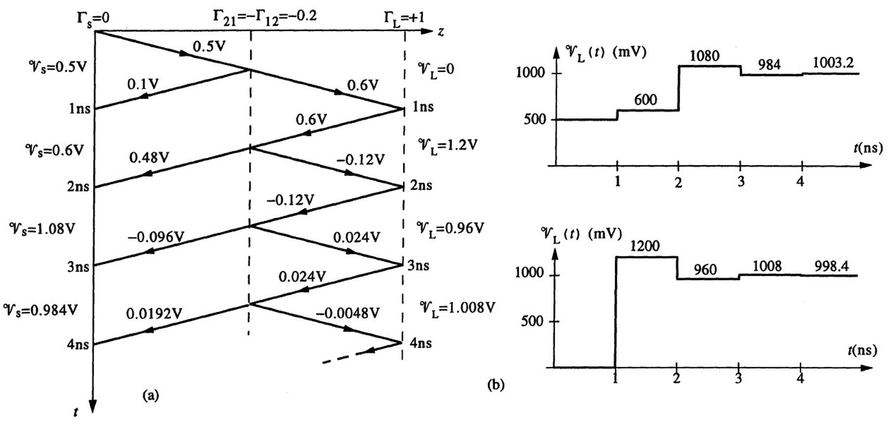
2.4Stepandpulseexcitationofalosslessline.
(a)Wefirstcalculatethereflectioncoefficientsatthesourceandload,andtheamplitudeofthe 9+ 1 voltagewavethatislaunchedat t = 0+:
Usingthese values,wecansketchthebouncediagraminFigure2.2a.Thesuccessive 9 and 9+ stepamplitudesarecalculatedusingtheloadandsourcereflectioncoefficients.Forexample, 91 and 9+ 2 arefoundfrom 9+ 1 as:
Thebouncediagramcanbeusedtosketchtheload-andsource-endvoltages,asshownin Figure2.2b.
ThisworkisprotectedbyUnitedStatescopyrightlaws andisprovidedsolelyfortheuseof instructorsinteachingtheircoursesandassessingstudentlearning. Dissemination orsaleofanypartofthiswork(includingontheWorldWideWeb) willdestroytheintegrityoftheworkandisnotpermitted.
(b)Wecanderivethesketchesfor 9s and 9L fromthesketchesinpart(a)bydelayingtheplotsby 0.3nsandsubtractingtheresult.TheresultingsketchesareshowninFigure2.3.
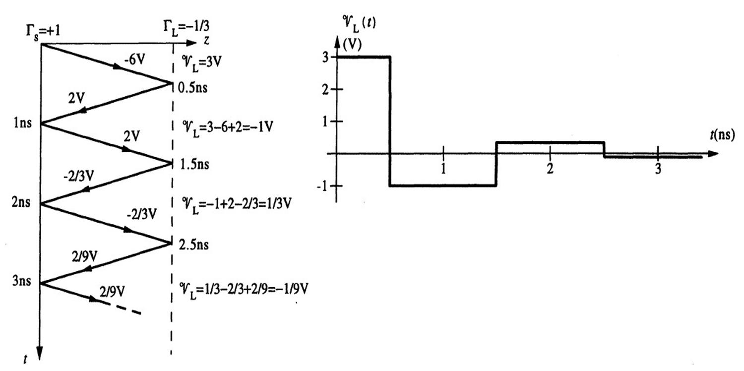
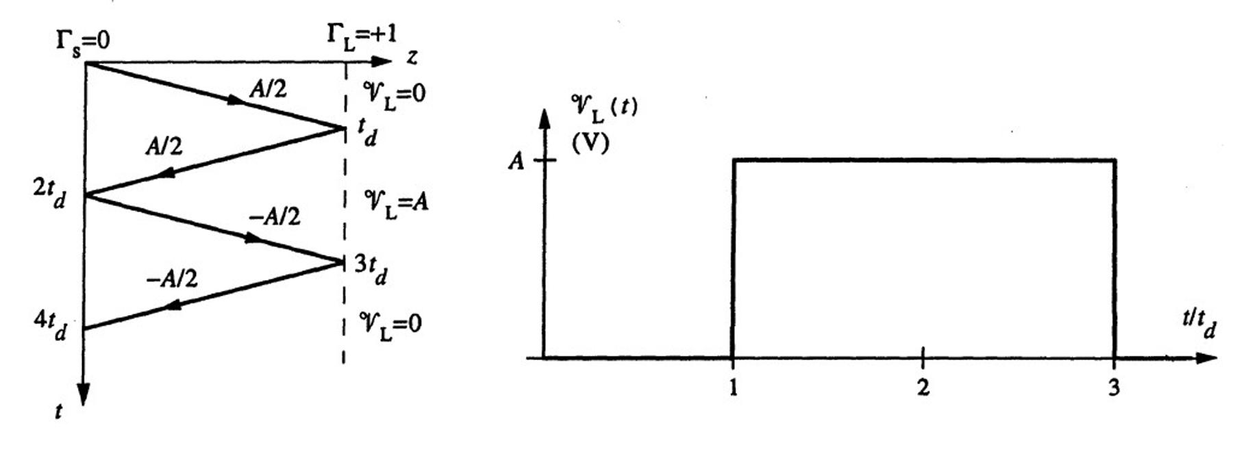
2.5Resistiveloads.
Since Rs = 0, Γs = 1.
(a)For RL = 25Ω,wehave
islaunchedatthesourceendoftheline.Usingthesevalues,thebouncediagramandtheload voltage 9L(t) versus t areasshowninFigure2.4.
(b)For RL = 50Ω, ΓL = 0.Thebouncediagramandthesketchoftheloadvoltageforthiscase areasshowninFigure2.5.
(c)For RL = 100Ω,theloadreflectioncoefficientis
ΓL = 100 50 100 + 50 =+ 1 3
Again, thebouncediagramand 9L(t) versus t areasshowninFigure2.6.
ThisworkisprotectedbyUnitedStatescopyrightlaws andisprovidedsolelyfortheuseof instructorsinteachingtheircoursesandassessingstudentlearning. Dissemination orsaleofanypartofthiswork(includingontheWorldWideWeb) willdestroytheintegrityoftheworkandisnotpermitted.
ThisworkisprotectedbyUnitedStatescopyrightlaws andisprovidedsolelyfortheuseof instructorsinteachingtheircoursesandassessingstudentlearning. Dissemination orsaleofanypartofthiswork(includingontheWorldWideWeb) willdestroytheintegrityoftheworkandisnotpermitted.
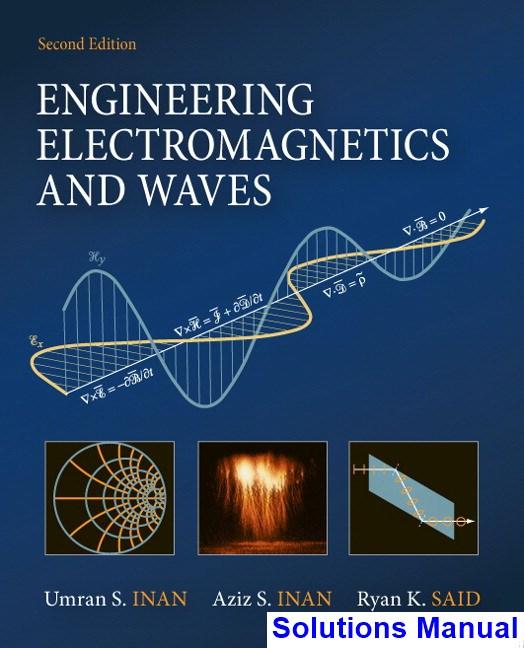
2.6Ringing. Using(2.7)and(2.9),wehave
Theone-waytimedelaycanbefoundas
Theincident voltagewavelaunchedatthesource-endat t = 0canbefoundusingthevoltage dividerprincipleas
Theload-end andsource-endreflectioncoefficientscanbefoundusing(2.12)and(2.14):
Next, wedrawabouncediagramupto t = 10ns,showninFigure2.7a.Usingtheload-end voltagevaluesonthebouncediagram,wecansketchtheload-endvoltage 9L(t) versustime,as showninFigure2.7b.

ThisworkisprotectedbyUnitedStatescopyrightlaws andisprovidedsolelyfortheuseof instructorsinteachingtheircoursesandassessingstudentlearning. Dissemination orsaleofanypartofthiswork(includingontheWorldWideWeb) willdestroytheintegrityoftheworkandisnotpermitted.
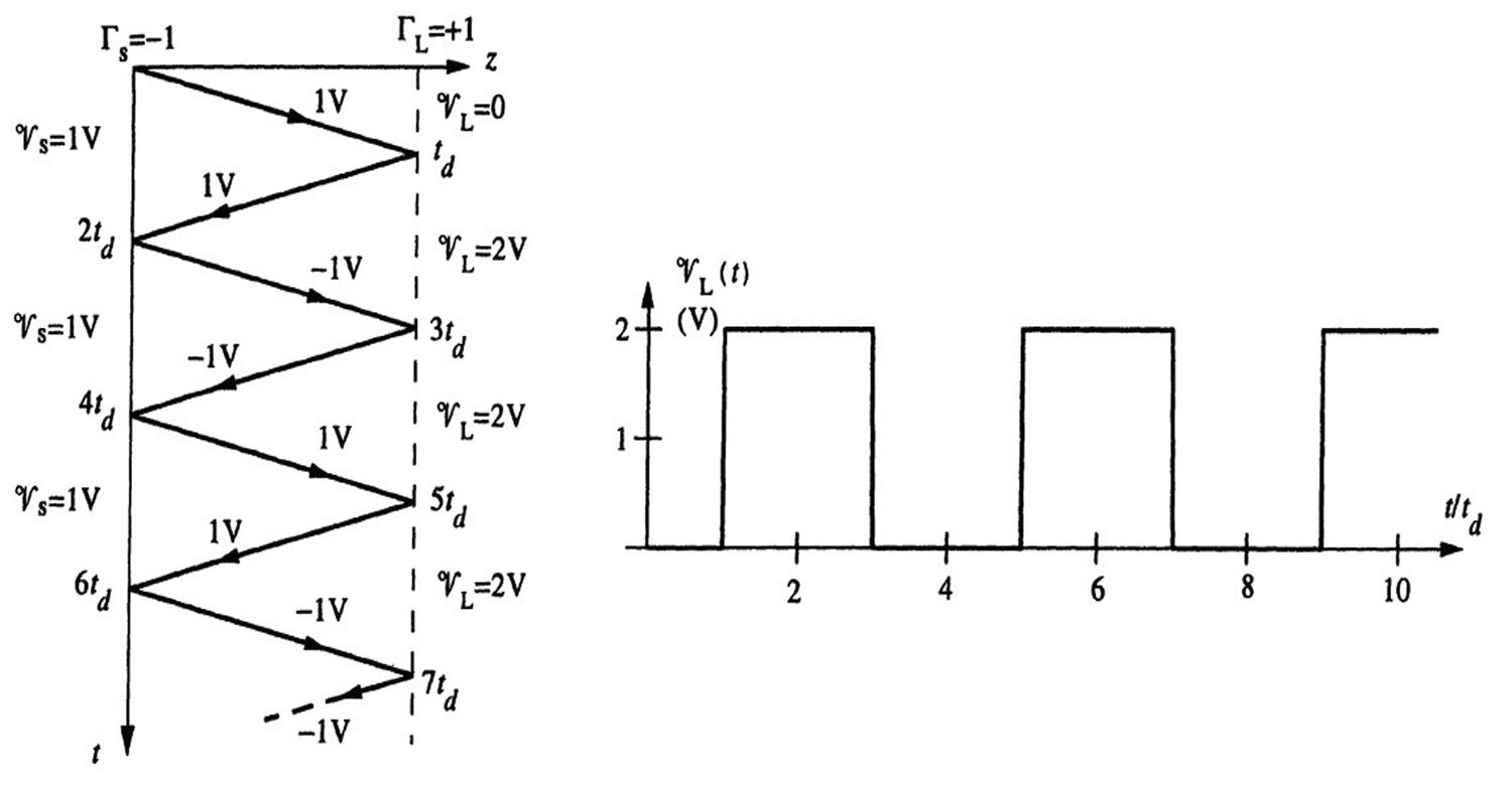
At t = 0 (i.e.,immediatelybeforetheswitchopenswhensteady-stateconditionsareineffect), thesourceendcurrent )s isgivenby )
theswitchopens),thesourceendcurrentissuddenlyforcedtogotozero,i.e., )s(0+)= 0.Wecan representthischangein )s asanewdisturbancelaunchedfromthesourceendofthelinestarting at t = 0.Theamplitudeofthisnewcurrentwaveanditsaccompanyingvoltagewavearegiven respectivelyby )+ 1 = )s(0+) )
willnotaffectthevalueoftheloadendvoltageuntil
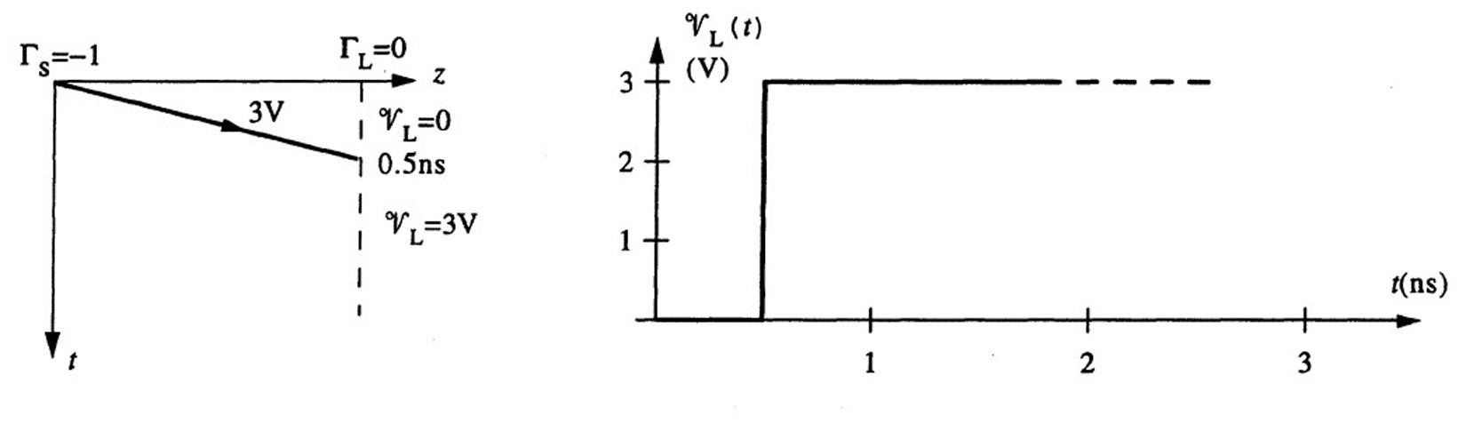
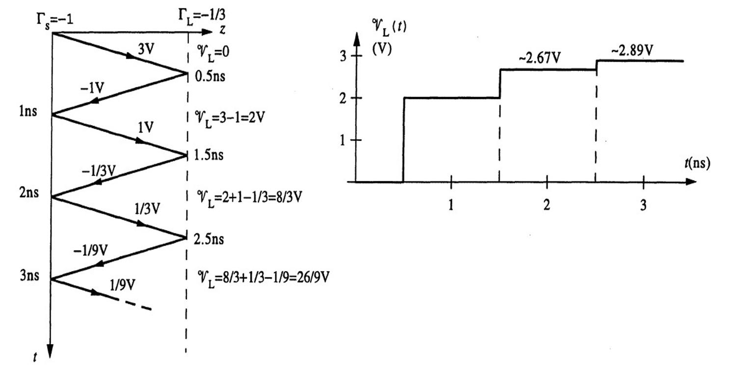
t < td, 9L(t)= 3V, regardlessofthevalueof RL.UsingthereflectioncoefficientvaluescalculatedinProblem2.5, wedrawthebouncediagramandsketch 9L(t) asafunctionof t foreachvalueof RL,asshownin Figures2.8,2.9,and2.10.
Thereflectioncoefficientsatsource1andsource2endsare,respectively,
ThisworkisprotectedbyUnitedStatescopyrightlaws andisprovidedsolelyfortheuseof instructorsinteachingtheircoursesandassessingstudentlearning. Dissemination orsaleofanypartofthiswork(includingontheWorldWideWeb) willdestroytheintegrityoftheworkandisnotpermitted.
ThisworkisprotectedbyUnitedStatescopyrightlaws andisprovidedsolelyfortheuseof instructorsinteachingtheircoursesandassessingstudentlearning. Dissemination orsaleofanypartofthiswork(includingontheWorldWideWeb) willdestroytheintegrityoftheworkandisnotpermitted.
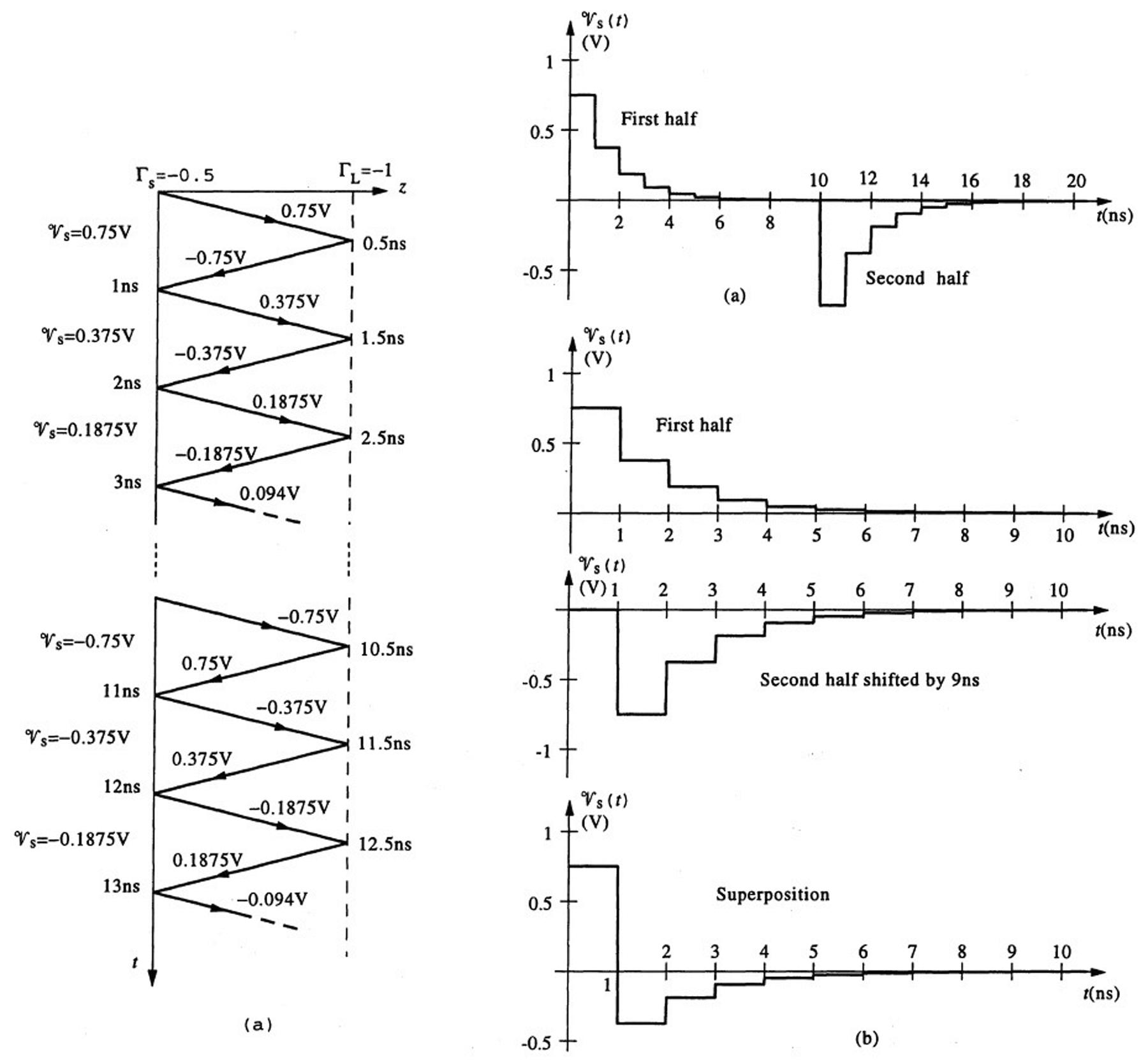
(a)Theinputvoltagehasapulsewidthof tw = 10ns,thatistheinputvoltageturnsoffat t = tw = 10ns.Werepresentthischangeintheinputvoltageasanewincidentvoltageofamplitude 9+∗ 1 = 9+ 1 = 0.75Vlaunchedatthesourceendofthelineat tw = 10ns.Thebouncediagram andthevariationofthesourcevoltage 9s(t) versus t areasshowninFigure2.12a.
(b)Forthecaseof tw = 1ns,thesourceendvoltage 9s(t) caneasilybeobtainedbyshiftingthe second-halfofthe 9s(t) sketchedinpart(a)by9nstotheleftandaddingitwiththefirsthalf.The finalplotfor 9s(t) versus t isasshowninFigure2.12b.
2.10Pulseexcitation.
Thereflectioncoefficientsatthetwoendsofthelineare(using(2.12)and(2.14))
At t = 0,an incidentvoltageofamplitude
ThisworkisprotectedbyUnitedStatescopyrightlaws andisprovidedsolelyfortheuseof instructorsinteachingtheircoursesandassessingstudentlearning. Dissemination orsaleofanypartofthiswork(includingontheWorldWideWeb) willdestroytheintegrityoftheworkandisnotpermitted.
ThisworkisprotectedbyUnitedStatescopyrightlaws andisprovidedsolelyfortheuseof instructorsinteachingtheircoursesandassessingstudentlearning. Dissemination orsaleofanypartofthiswork(includingontheWorldWideWeb) willdestroytheintegrityoftheworkandisnotpermitted.
ThisworkisprotectedbyUnitedStatescopyrightlaws andisprovidedsolelyfortheuseof instructorsinteachingtheircoursesandassessingstudentlearning. Dissemination orsaleofanypartofthiswork(includingontheWorldWideWeb) willdestroytheintegrityoftheworkandisnotpermitted.
2.11Observerontheline.
(a)Usingthesketchof 9ctr versus t provided,theinitialvoltagelaunchedonthelineisgivenby
(b)Superimposingthedirectandreflectedpulses,thevoltage 9ctr(t) isasdrawninFigure2.16.
2.12Cascadedtransmissionlines.
Thereflectioncoefficientsare
and ΓL = +1(since RL = ∞)respectively.Thebouncediagramandthesketchesofvoltages 9s(t) and 9L(t) areasshowninFigure2.17.
2.13Time-domainreflectometry(TDR).
Theinitialvoltage 9+ 1 launchedfromthesourceendofthelineisgivenby
Thesourceendvoltage 9s(t) changesfrom0 5Vto0 375Vwhenthevoltagewavereflected fromthejunctionpointbetweenthetwolinesreachesthesourceendoftheline,i.e.,attime 2td1 = 1nsor td1 = 0.5ns.Thelengthofthefirstline l1 canthenbefoundas l1 = vptd1 = (20cm-(ns) 1)(0.5ns)= 10cm.Thevoltage 91 reflectedfromthejunctionpointcanbeexpressedintermsof 9+ 1 as
ThisworkisprotectedbyUnitedStatescopyrightlaws andisprovidedsolelyfortheuseof instructorsinteachingtheircoursesandassessingstudentlearning. Dissemination orsaleofanypartofthiswork(includingontheWorldWideWeb) willdestroytheintegrityoftheworkandisnotpermitted.
L
t
Figure2.18
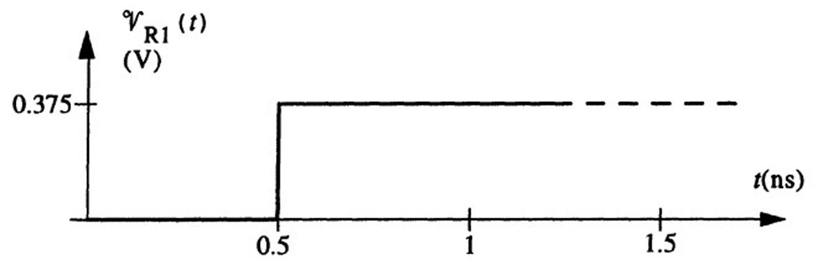
91 = (R1 || Z02) Z01 (R1 || Z02)+ Z01 9+ 1 where R1 || Z02 = R1Z02 R1 + Z02
Whenthereflected voltage 91 reachesthesourceendoftheline,noreflectiontakesplacessince Γs = 0.Thus,wehave 9+ 1 + 91 = 0.375V → 91 = 0.125V.Usingthisvalueintheabove expressionwith 9+ 1 = 0.5Vand Z01 = 50Ω,wefind R1 || Z02 = 30Ω.Since Z02 = 75Ω,wehave R1 = 50Ω.Thevoltage 9R1(t) versus t isplottedasshowninFigure2.18.
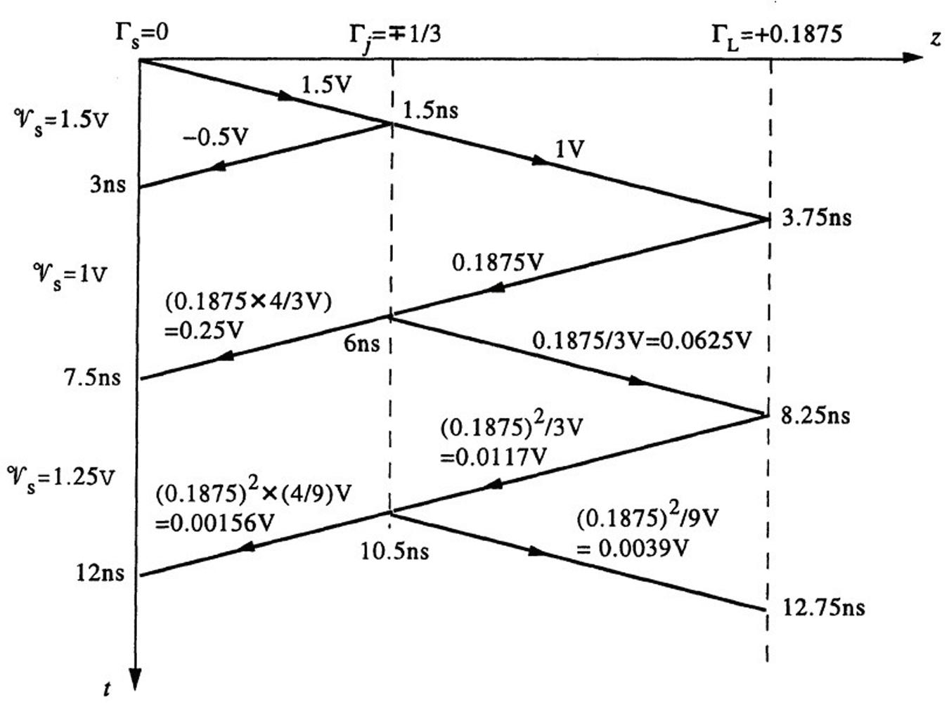
2.14Time-domainreflectometry(TDR).
(a)Theinitialvoltagelaunchedatthesourceendofthetransmissionlinesystemisgivenby 9+ 1 = Z01 Rs + Z01 V0 = Z01 100 + Z01 (3V)= 1 5V → Z01 = Rs = 100 Ω
Theone-waytimedelayofthetwotransmissionlinescanbefoundas td1 = 3ns/2 = 1.5nsand td2 =(7.5ns 3ns)/2 = 2.25ns.Since Γs = 0,thesourceendvoltage 9s at t = 2t+ d1 canbe
ThisworkisprotectedbyUnitedStatescopyrightlaws andisprovidedsolelyfortheuseof instructorsinteachingtheircoursesandassessingstudentlearning. Dissemination orsaleofanypartofthiswork(includingontheWorldWideWeb) willdestroytheintegrityoftheworkandisnotpermitted.
2.15Time-domainreflectometry(TDR).
ThisworkisprotectedbyUnitedStatescopyrightlaws andisprovidedsolelyfortheuseof instructorsinteachingtheircoursesandassessingstudentlearning. Dissemination