MULTICOLOUR 3D PRINTING
Geovisualisation using Fused Filament Fabrication
This document was created as part of the Diploma Thesis: Multicolour 3D-Printed Geovisualisation.


Contents Key Terms 3 FFF 3D Printing 4 Multicolour 3D Printing 6 3D Printer Safety 7 Design Considerations 9 Geovisualisation Resources 11 Printing a Model 12 Post-processing 20 General User Testing 22 Visually Impaired User Testing 23 Additional Resources 25 “With 3D printing, the only limit is your imagination.” - Charles Hull
Key Terms
• 3D: Three-dimensional
• 3MF: 3D Manufacturing Format is an open-source file format developed specifically for 3D printing.
• CAD: Computer-Aided Design
• Extruder: The assembly that dispenses filament during a print through a small nozzle.
• FDM: Fused Deposition Modelling is a material extrusion process that uses a continuous flow of filament to create an object.
• FFF: Fused Filament Fabrication is the open-source name for FDM.
• Filament: Thermoplastic material used to build objects in FDM/FFF.
• G-code: Coding language used to transmit instructions to a 3D printer’s control system to tell the printer how to print the 3D model.
• PLA: Polylactic Acid is the most common type of filament used in FFF.
• STL: Stereolithography file format is one of the recommended file formats for 3D printing.
• Wipe/Transition tower: Tower used to clear (or purge) the extruder of the current filament.

3
FFF 3D Printing
3D printing is an Additive Manufacturing technique that creates physical objects by the deposition of a material in layers. Firstly, an object is designed as a digital 3D model. This model is then sliced and converted to G-code that the printer can read. The printer uses the G-code to control the movement of the extruder to produce the final physical object.
There are seven types of 3D printing technologies. Material Extrusion is one of these types and works by squeezing a material through a nozzle and onto a build plate, layer by layer. FFF or FDM falls under the Material Extrusion category and is the most widely used 3D printing technology. The 3D printing technologies can be seen in the chart to the right.

4

Advantages of FFF:
• Fast
• Low cost
• Common thermoplastic filament
Disadvantages of FFF:
• Rough surface finish
• Usually requires supports
• Limited accuracy
KGI 3D Printing Lab 5
Multicolour Printing Methods
Multicolour 3D printing, sometimes referred to as multi-material 3D printing, uses multiple filaments of varying colours or materials to create an object. FFF technology remains the cheapest way to produce multicolour prints. Many different devices on the market employ different methods to achieve multicolour prints.
Based on the devices available in the 3D Printing Lab, the following methods were tested:
1. Pause and Swap
2. Single Extruder with Multi-Material Add-on
3. Tool Changer
Devices tested:
• Original Prusa i3 MK3S+ with Mosaic Palette 3 Pro (up to 8 colours)
• Original Prusa XL (up to 5 colours)
• Bambu P1S with Automatic Material System (up to 8 colours)


3D Printer Safety
Safety measures are important when working with 3D printers to prevent exposure to potential health and safety hazards. Users should understand the risks associated with FFF printers and adhere to safety practices and procedures.
Potential hazards include, but are not limited to:
• Fire hazards from electrical faults or heating-related failure
• Mechanical hazards from moving parts (cutting yourself when removing supports or by sharp edges and getting your finger pinched or burned by the nozzle)
• Inhalation of airborne particulates, for example volatile organic compounds (VOCs)
• Electrical shock from the high voltage of the printer
Printer Maintenance
Regular maintenance is essential to ensure optimal performance and longevity of a 3D printer. Follow the printer manual to complete any maintenance work that is needed, especially calibrating the printer, and updating firmware.

7
Safety Measures to Follow

Before During After
Review the specific printer’s instructions and operations manual. Inspect the printer to ensure it is clean and in good working condition.
Do not touch the hot print bed and extruder while in operation. Limit time spent observing the printer while it is in operation if it is not enclosed.
Cool down and turn off the printer.
Clean-up the print bed and surroundings of any waste material and properly dispose of the waste (e.g. wipe tower).
Wash hands after handling printed objects.
8
Design Considerations
In this section, we explore the essential software and considerations to make when creating vibrant multicolour prints. Transposing geovisualisation ideas from paper or digital format to something tactile and tangible requires careful consideration about the users and the equipment available to produce it. Some of these considerations such as choosing the right CAD/modelling software can be up to personal preference, however, there are other steps that need to be taken to optimise a design for multicolour printing.
Key considerations to make while designing models for printing include:
• Ensuring the model is manifold/watertight (has no holes)
• Ensuring all faces/walls are oriented in the correct direction
• Repairing the model in the slicer application if necessary
Design Tips
• Separate layers or sections with different colours into different STL files. This makes the colouring and slicing processes easier than manually painting each section/part in the slicer application.
• Save the coloured model in 3mf format for use in the slicer as this will retain the colour information.

9
Design Tips
• Set the infill to a single extruder/colour, this may help to reduce the print time if the model has many parts of different colours.
• It is possible to make braille characters with rounded top cylinders/dots in bulk in SketchUp using the Round Corner and Joint Push Pull extensions.
• Enable ironing to achieve smooth top surfaces, however, be mindful that this significantly increases the print time. Ironing is especially good for some aspects of tactile maps that will improve the user experience.
• Do not enable ironing of the top layer if braille is present as this will cause streaking.



PrusaSlicer Desktop Desktop Web Bambu Studio Canvas Slicing
Software (used in testing)
Geovisualisation Resources
The combination of the following resources proved effective in creating various models to convey geospatial data (shown throughout the document). However, working with geospatial data to make these models is still a challenging task. Software such as ArcGIS Pro has limited export capabilities to 3D formats. Hence, there is a need for more simplified processes to create equivalent 3D printable maps from digital or paper maps.
Data Sources
Copernicus DEM
OpenStreetMap
Corine Land Cover
Cadmapper
ArcDATA PRAHA
National Geographic
Software/Tools
• ArcGIS Pro
• QGIS with DEMto3D Plugin
• Inkscape
• SketchUp
• Blender
• 3D Builder
Open Topography
USGS
GEBCO Bathmetry
• Autodesk Netfabb
• Thingiverse
• Printables.com
11
Printing a Model
Printing a model can be the most time concuming step as it is dependent on the size of the model, the printer and sometimes luck. The following steps were applied throughout the the research. Whether you are a novice or a seasoned 3D printing enthusiast, this guide will empower you to create stunning geovisualisations. The “geomodels” that were created in this study are showcased in the following pages.
• Load model on an SD card or USB
• Load the required filaments into the printer or multi-material device
• Apply bed adhesive spray to ensure the part sticks to the bed while printing
• Hit Print!!!
• Check the model intermittently to ensure printing is progressing as expected
• At the end of the print, allow the print bed to cool down before removing the printed part
• Carefully remove the part from the print bed

Model List
13
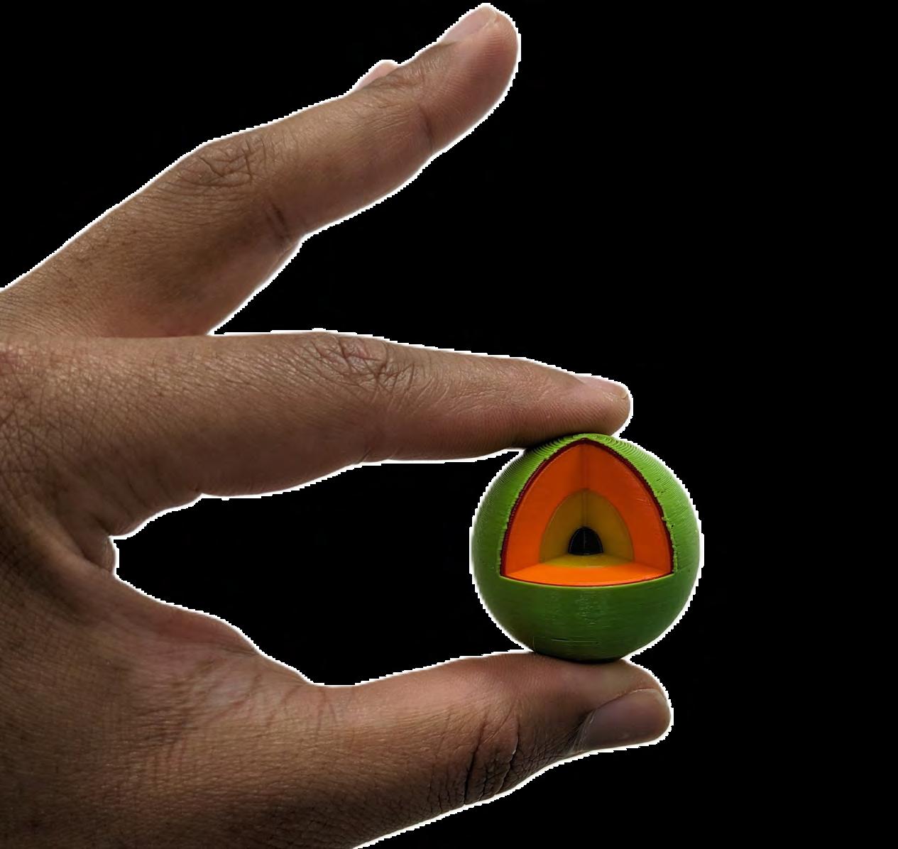
# Model Name Printer Dimensions (in mm) L×W×H 1 Kingston Mountains Prusa i3 MK3S 117×114×30 2A New York City Prusa XL 181×225×59 2B New York City Prusa i3 MK3S & Palette 3 Pro 131×157×84
Praha Metro Map Prusa XL 301×213×7 3B Praha Metro Line A Prusa XL 168×242×6 3C Praha Metro Line B Prusa XL 162×329×6 3D Praha Metro Line C Prusa XL 162×281×6 4A Earth Structure Prusa i3 MK3S & Palette 3 Pro 69×73×38 4B Earth Structure Prusa XL 81×68×38 4C Earth Structure Bambu P1S & AMS 203×162×64 5 Austria Population Density 2023 Prusa XL 170×87×9 6 Population Structure Pardubický kraj Prusa XL 257×190×14 7A Lucerne Land Cover OSM Prusa XL 211×149×13 7B Lucerne Land Cover CLC Prusa XL 211×149×13
3A
Model 1: Kingston Mountains
Data: Copernicus 30m DEM

Printing Challenges
• The Palette 3 Pro attachment to the printer was dislodged by filament unloading.
• Palette 3 Pro experienced filament jams and breakage caused by an old filament.
• Both the Prusa XL and Palette 3 Pro experienced slicing errors with streaks of misplaced colours
• Palette 3 Pro experienced significant colour bleed on Model 4A.
• On the Prusa XL, a loose screw on one of the tools caused repeated printer collision errors.
• On Model 7B using the Prusa XL, the black filament was defective/old and caused a blockage in the extruder.
• While printing Model 4C on the Bambu P1S, the printer paused printing several times because of the filament spool shifting in the AMS.
14
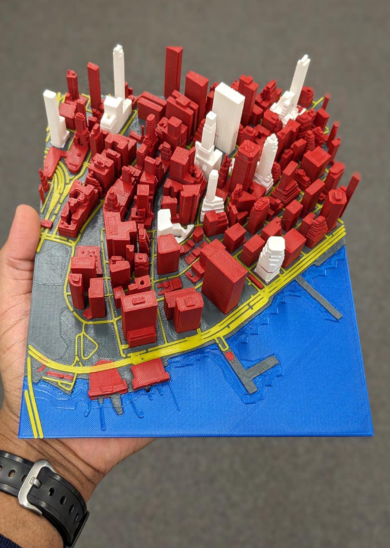
Data: Cadmapper
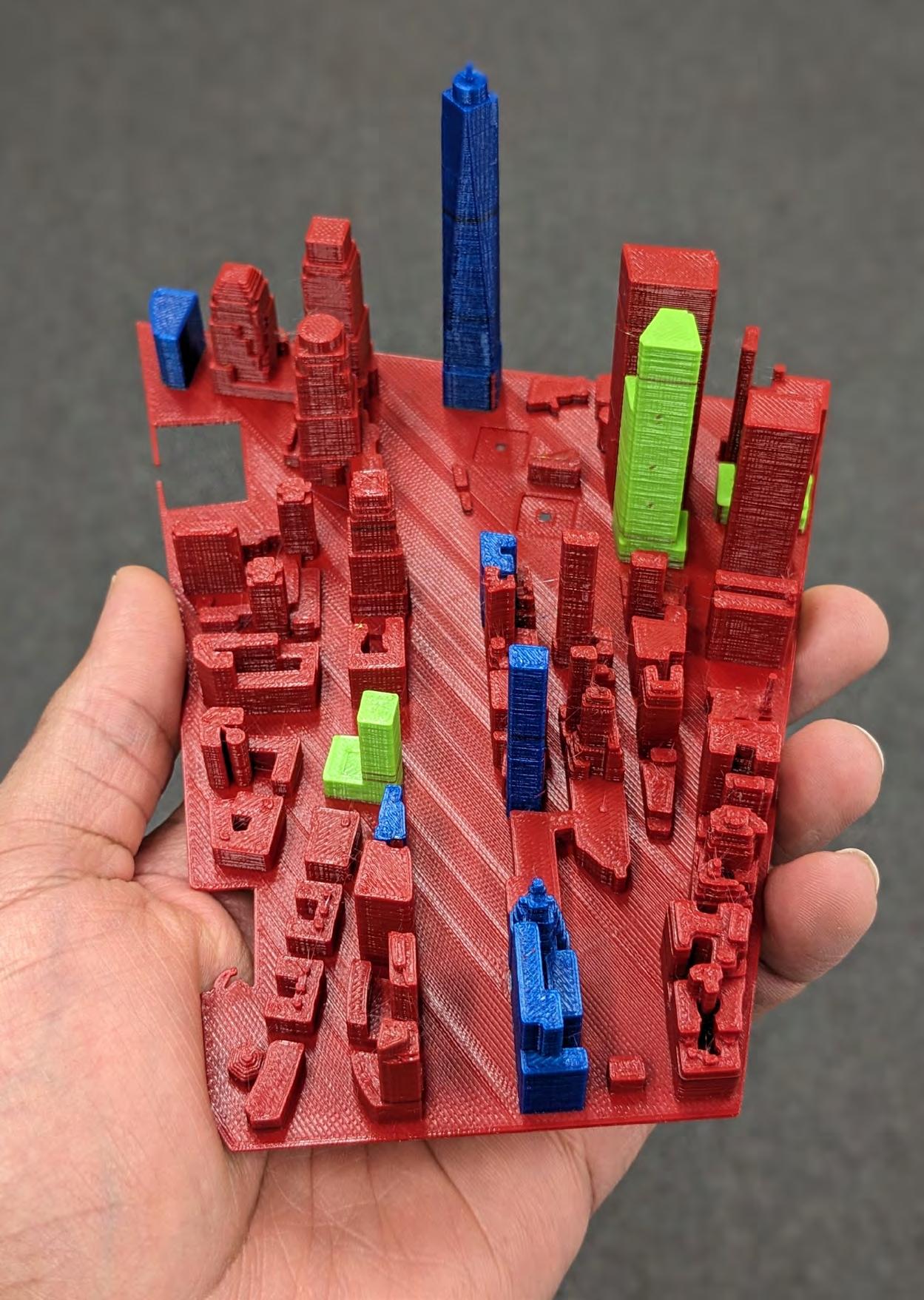
Data: Thingiverse
Model 2A: New York City
Model 2B: New York City
15

Model 3A-D: Praha Metro Map
Data: PID A


C
16
D B

Data: National Geographic
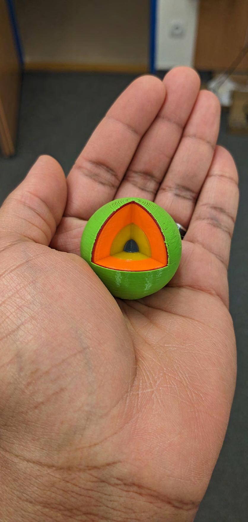
 Model 4A-C: Earth Structure
4A 4B 4C 17
Model 5: Austria Population Density 2023
Data: Bundesanstalt Statistik Österreich

Model 6: Population Structure Pardubický kraj
Data: ARCDATA PRAHA

18
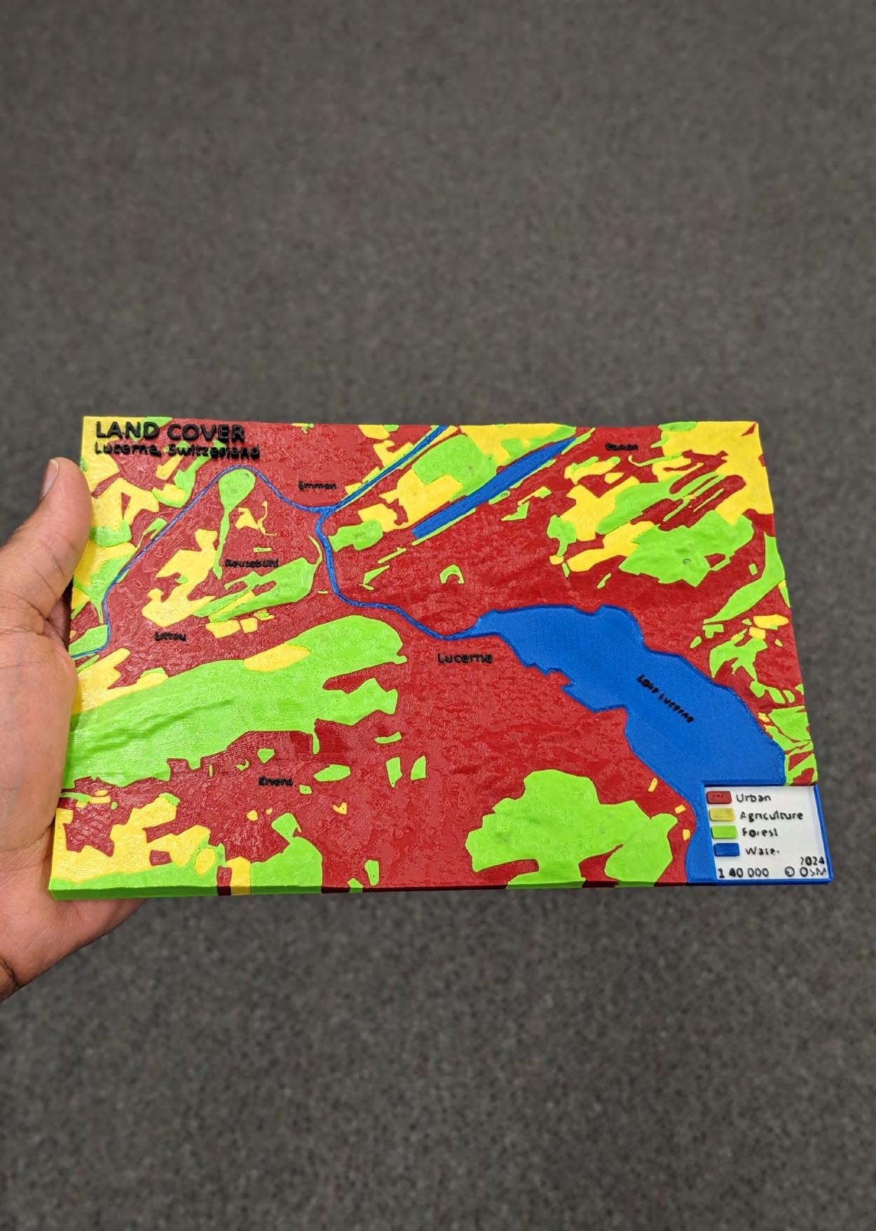
Data: OpenStreetMap
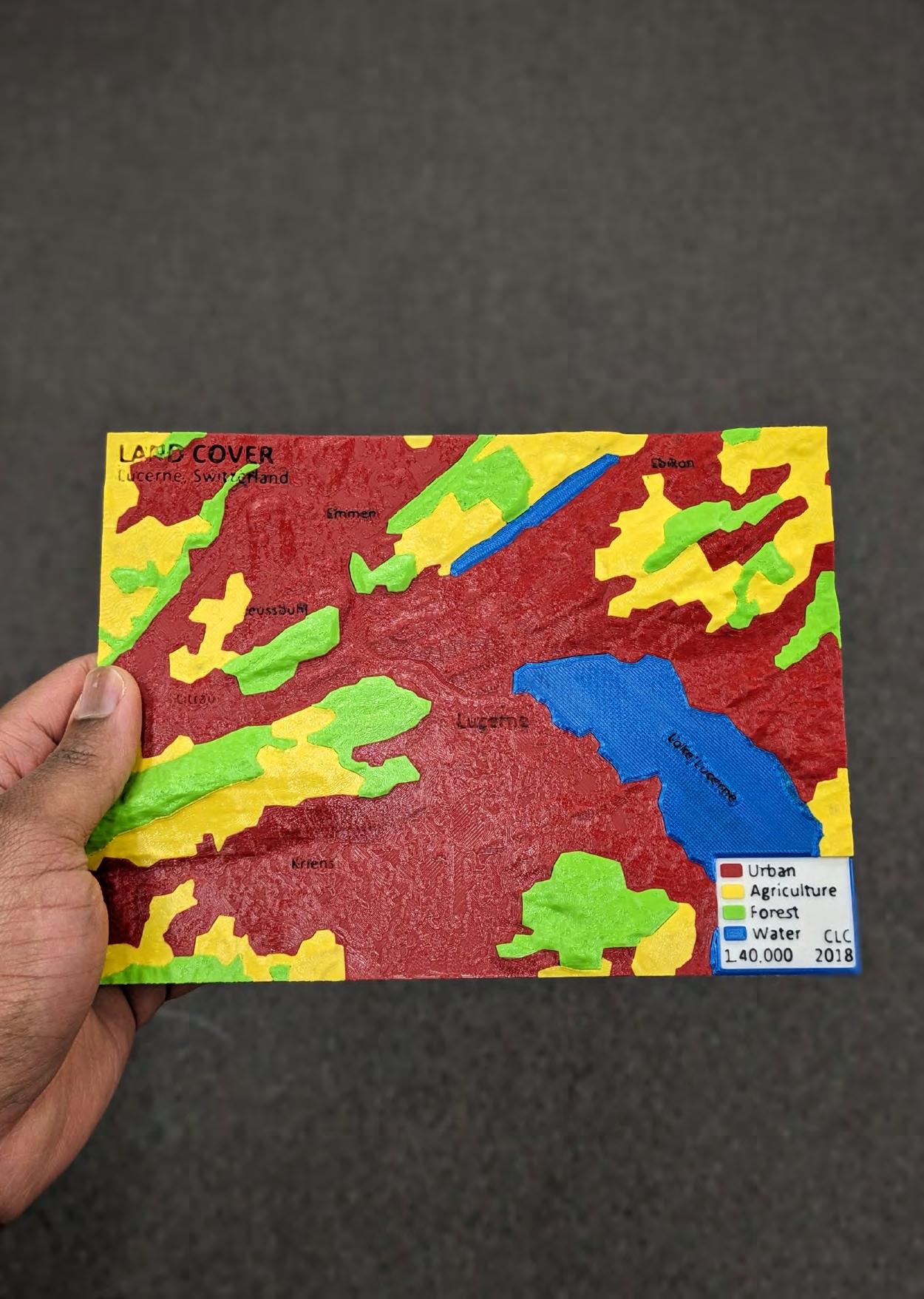
Data: Corine Land Cover 2018
 Model 7A: Lucerne Land Cover OSM
Model 7B: Lucerne Land Cover CLC
19
Post-processing
FFF printing results in models having layer lines, seam lines and support marks. These blemishes need post-processing to improve the mechanical characteristics and appearance of the model. Below, a few tips or techniques are provided to enhance the appearance of the final printed product. Post-processing steps can transform simple models into professional-quality works that leave a lasting impression.
Tips
• Remove supports carefully
• Use a filament cutter and tweezers to remove unwanted pieces of extruded filament.
• Use sandpaper to smooth areas where the layers are rough or extra smoothness is needed. For example, to smooth the dots of braille.
• Use a heat gun to get rid of “stringing”

20


21
General User Testing
Model 6: Population Structure Pardubický kraj was used to collect feedback from the general public. Some of the findings inlcuded:
POPULATION STRUCTURE
Pardubický kraj, 2023
90%
Correctly answered all the map interpretation questions.
Found the 3D-printed map to be more attractive than the paper map.
Agreed that the use of multiple colours aided in better understanding the 3D-printed map and also made it more appealing. 65% 90% 90%
Found the 3D-printed map to be more understandable than the paper map.


22
Česká Třebová Hlinsko Holice Chrudim Králíky Lanškroun Litomyšl Moravská Třebová Pardubice Polička Přelouč Svitavy Ústí nad Orlicí Vysoké Mýto Žamberk
Pop. 65 and over Pop. 15-64 Pop. 0-14 Age Group 50,000 8,719 127,477 Date: Mar. 2024 Map Design: Jevaughn Henry Credits: ArcČR, ARCDATA PRAHA Population Total Population Density Min. 55 150 100 75 pop./km² Max. 311 0 5 10 km
Visually Impaired User Testing
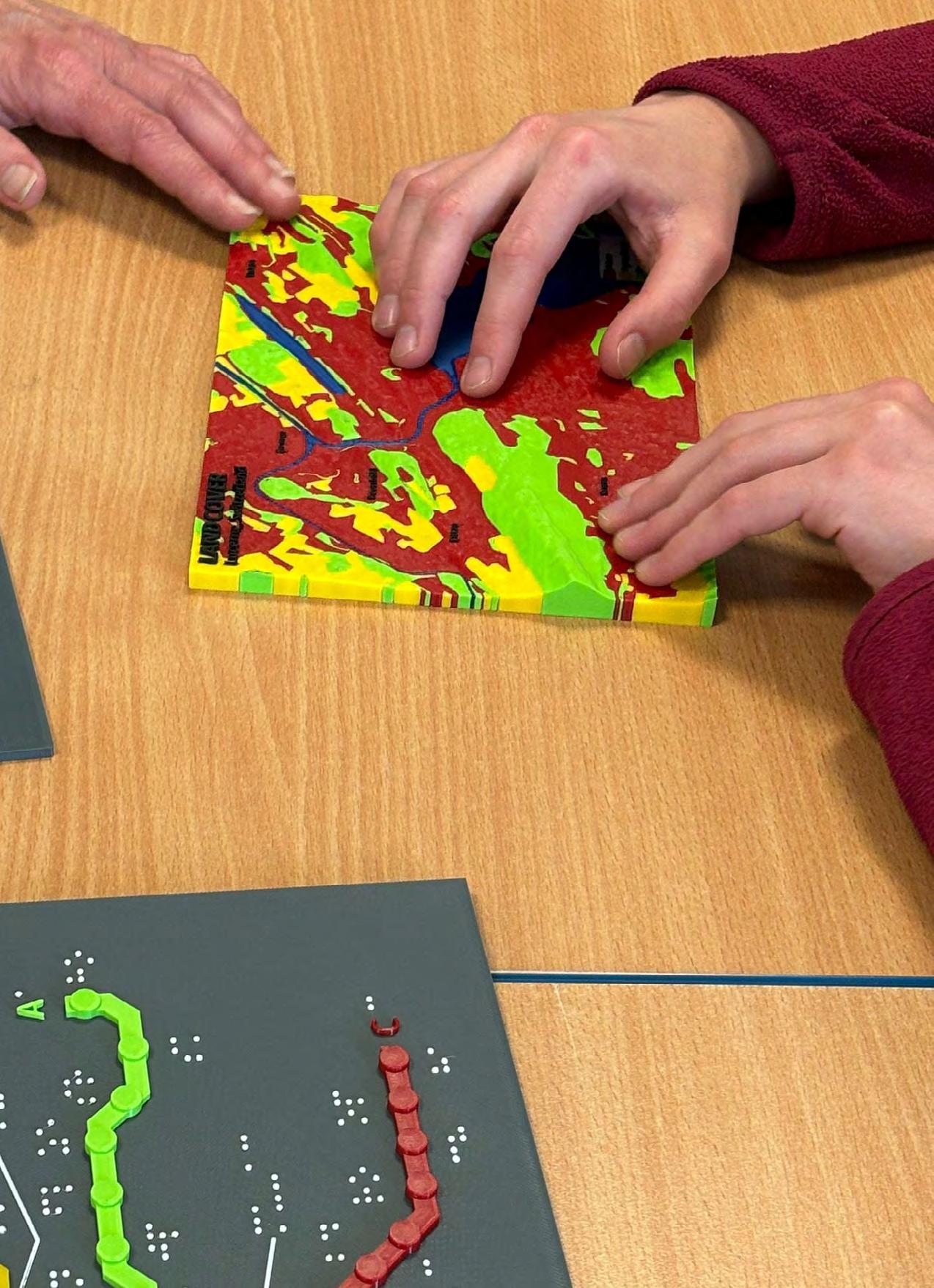
Model 3A, 3B and 7A were tested by students in Prague with varying levels of visual impairment, from blind to having some remnants of sight. The main feedback included:
• The models were found to be very helpful, especially the model of Praha Metro Line A.
• The braille was very readable even though the surface of the dots was a bit unusual for the users.
• In the braille, some words were missing their first letter (e.g. instead of Metro Praha there is etro raha). The reason for this was a mistake in trying to use capital letters as capital letters are not present in the braille font.
• Some labels were more challenging to link with the appropriate station because of spacing (Model 3A).
• Transfer stations could have been more distinguishable.
• The land cover model (7A) could be adapted for the visually impaired with changes to the use of colour for features and elevation.
Designing Braille in SketchUp
1. Use braille font to extrude words as dots
• Braille Height = 7.5 mm
• Extrusion height = 0.8 mm
2. Use Round Corner tool from the RoundCorner extension to round the tops of the cylinders
• Offset = 0.7 mm
• # of Segments = 10
PrusaSlicer Settings
1. Extrusion Width:
• External perimeters = 0.4 mm
• Perimeters = 0.4 mm
2. Speed
• Small perimeters = 5 mm/s
23

24

Prusa Knowledge Base
https://help.prusa3d.com/ Bambu Lab Wiki
https://wiki.bambulab.com/en/home Mosaic Manufacturing Support
https://support.mosaicmfg.com/c/Root
Additional
Resources
25
Credits
This guide was created based on the results of the Master Thesis entitled, “Multicolour 3D-Printed Geovisualisation.” 2024
AUTHOR
PHOTOGRAPHY
GRAPHIC DESIGN
Jevaughn Henry




26


 Model 4A-C: Earth Structure


 Model 7A: Lucerne Land Cover OSM
Model 7B: Lucerne Land Cover CLC


