BIM SQUAD

BIM SQUAD
SHAPE THE WORLD
Pilot Project WeZig Building
BIM SQUAD
3 BIM SQUAD Global BIM Management: FMT 5 Weizig Building Pilot Project 7 “We Deliver the Infrastructure that Brings your Ideas to Reality” 9 BIM Capabilites 10 Phase 1: Pre Tender 13 Naming Conventions 18 Clash Matrix 20 SCRUM Retrospective 22 Phase 2: Design 25 Design Authoring 26 SCRUM Retrospective 30 Phase 3: Pre- contruction 32 Visual Communication 36 Construction Scheduling 38 Cost Estimation 42 Energy Analysis 46 Structural Analysis 52 SCRUM Retrospective 56 Phase 4: Asset/ Operations Management 58 Asset Information Model AIM 62 Sprint Planning Overview 72 Model Progress Summary 73 Scrum Retrospective 74 Phase 5: Implementation 77 Communication 78 Agile Management 79 BIM Implementation Development 82 Business Process Management 86 SWOT Analysis 88 CDE Implementation Roadmap 90 BIM Audit and Performance Metrics 92 Execution Process Map 94 Acknowledgements 96
Syllabus outline across timeline
This diagram shows how the Global BIM Management Masters Program organizes the project delivery milestones. It is important to note that the Final Masters Thesis runs parallel to the curriculum. The following table summarizes the program’s topics.
Project Milestone
Block1 : BIM Management
Block 2: BIM for Design
Block 3: BIM for construction
Block 4: BIM for asset Management
Block 5: BIM implementation
Block 6: Final Masters Thesis
BIM SQUAD
Parallel Curriculum
M1 Information Management
M2 Information Management
M3 Coordination
M4A Authoring in design with BIM Software (Revit)
M4B Authoring in design with BIM Software (ArchiCAD)
M5 Analysis tools interoperability
M6 Planning and cost estimation in construction
M7 Pre construction, construction and handover with BIM authoring software
M8 Coordination and site management
M9 Information exchange in asset management
M9 Information exchange in asset management
M10 Implementation strategies by stage
M11 Implementing BIM
Final Masters Thesis delivery and defense
B1 BIM Management B2 BIM for Design B3 BIM for Construction B4 BIM for Asset Management B5 BIM Implementation M1 M2 M3 M4 M6 M7 M5 M8 M9 M10 M11
Global BIM Management: FMT
We are pleased to welcome you to our final master’s thesis (FMT). Zigurat Institute of Technology, in collaboration with University of Barcelona, curated this assignment to showcase student knowledge and expertise gained within the Global Building Information Management (BIM) program. The FMT ran parallel to the master’s syllabus for a period of 12 months. Throughout the project, information requirements were delivered at milestones, with its final delivery scheduled for November 2022.
This FMT aims to accurately simulate a real-world project using the highest level of BIM maturity. A second goal is to work collaboratively. Among the six members of this project are engineers specializing in architectural, structural, and mechanical fields. The international approach that we use enhances this collaborative experience as we have members from Canada, New Zealand, India, and the United Arab States. A final objective is to implement communication and implementation strategies to effectively manage the project’s development.
FMT Considerations
The following are some of the considerations that we were required to implement for our deliveries:
1. Learn about the importance of applying standardized and open data in response to the client (appointing party, ISO 19650) information requirements.
2. Use innovative and consistent tools and methodologies to solve a building Project in a collaborative and multidisciplinary way.
3. Implement client-oriented project management techniques, such as Agile
4. methodologies.
5. Simulate an IPD (Integrated Project Delivery).
6. Understand the importance of the owner and asset manager as the final beneficiary of BIM.
7. Embrace the implementation of the openBIM approach, using buildingSMART standards, such as the IFC, MVD and BCF. IPD
8. Understand the importance of the Information Requirements and how to create the appropriate response throughout the creation and update of the BIM execution plan.
9. Learn to make design decisions accordingly to the other stakeholders operating in different life-cycles stages.
10. Use BIM authoring modeling and management tools in the context of project development.
11. Embrace the interoperability between different software platforms,
12. throughout the use of open standards (IFC, BCF, COBie, gbXML, ...).
13. Learn to calculate the cost of construction and plan its execution using open standards as a reference and source
of information.
14. Understand the need for developing different Information Models per each of the different Life-Cycle stages.
The Master’s in Global BIM management program prepares participants to champion BIM across a wide range of AEC industries globally. Throughout the entire project lifecycle, this program addresses the application of the latest technologies and implementation methodologies. In addition to being recognized as the most advanced and innovative academic or technical programs in the BIM Management sector, program graduates receive accreditation from CANBIM and Autodesk, as well as training that can be applied to bre ACADEMY and Bentley Institute accreditation as well. As part of the educational structure, participants are presented with the tools, methodologies, and competencies required to train tomorrow’s BIM leaders and prepare profiles that will contribute to the transformation of business by serving as BIM managers, implementation specialists, and consultants.
Learning Objectives
Its general objective is to expose participants to the BIM ecosystem, and the Architecture, Engineering and Construction industries as they relate to managing an asset throughout its life cycle. A participant must demonstrate both an understanding of technical administration and a solid understanding of project management before they are able to assume the role of a BIM manager.
A secondary objective is to master BIM modeling, coordination, planning, cost estimation, and asset management tools. Interoperability workflows and agile/lean management are used across Common Data Environments to enhance collaboration and communication.
5
Global BIM Management: FMT
This diagram shows how the Global BIM Management Masters Program organizes the project delivery milestones. It is important to Planning 2D 3D 4D 5D 6D 7D
MANAGEMENT
Communication
Task management


Roles and responsiblities
Waste management
Time management
Scope
DOCUMENTS SHAPE
Existing conditions model (scanning, ground penetration)
Safety & Logistics Model
Animation, rendering, walkthroughs
BIM driven prefabrication
Laser accurate BIM driven field layout
SCHEDULING
Project phasing simulations
Lean scheduling (last planner. Just in time (JIT), detailed simulation installation) Visual validation for payment approval

ESTIMATING
Real time conceptual modeling and cost planning
Quantity extraction support detailed cost estimates

Trade verifications (structural steel, mechanical plumbing, electrical)


Value Engineering (visualizations, quantity extractions)
Prefabrication solutions (equipment rooms, MEP systems, unique architectural and structural elements)
Trello, Slack, Zoom, Google


Meets
CDE: BIMsync
Adobe Indesign, Microsoft: word, excel

Revit, Archicad, Teckla

Bentley- Syncro Microsoft Excel, Trimble, Solibri
SUSTAINABILITY
Conceptual energy analysis via D Profiler
Detail energy analysis via Eco Tech
Sustainable element tracking
LEEP Tracking
FACILITY MANAGEMENT
APPLICATIONS
Life Cycle BIM strategies
BIM As-built BIM embedded O&M Manuals
COBie data population and extraction

BIM maintenance plans and technical support
Navisworks, SCIA COBie, integrated IFC models
Global BIM Management: FMT

before 1.1.02
Weizig Building Pilot Project
Location: Barcelona, Spain
Building area: 2600 sqm
Construction type: Concrete Structure Office Building
The Weizig Building was developed as a pilot project to simulate global BIM management capabilities. The solutions are developed over the course of a year and delivered to meet specific project milestones and information requirements. Among the solutions demonstrated by our international team of six experts are:
1. Establish asset information management standards and specifications.
2. Implement CDE, openBIM practices, and contractual frameworks to develop collaborative workflows.
3. Demonstrate expertise in 3D, 4D, 5D, 6D, and 7D BIM simulations.
4. Demonstrate Agile and Lean management capabilities.
FEB 6, 2022 FEB 20, 2022 JUN 5, 2022 JUN 12, 2022 AUG 28, 2022 OCT 16, 2022 NOV 20, 2022
Setup
1 Pre- tender Phase 2 Design Secondary Setup Phase 3 Pre- construction Phase 4 Asset/ Opperations Management Phase 5 Implementation 7
Pilot Project
Initial
Phase
Weizig Building
Jessica is an architectural designer, BIM specialist and creative director at Eliah Studios. As a designer, her ultimate goal is to rethink and reshape physical and systematic infrastructure to develop communities. Collaborates with educators and industry professionals on the development of technology and design.

Simon is a global entrepreneur and strategist, specialized in technological innovation and sustainable development.
Ayodele is a registered civil engineer and a BIM expert in Nigeria. Over the past ten years, he has gained extensive experience as a construction expert, contributing to the successful completion of numerous building projects across Africa. He is enthusiastic about optimizing client success using his proficient knowledge of authoring and BIM.

Oshadi has a UK chartered construction manager qualification. He is an experienced quantity surveyor and preconstruction manager with over 12 years of experience.

Sean is a certified building design practitioner with a background in architecture and structural engineering. Having worked in this construction industry for over twelve years, Sean is proficient in a variety of BIM tools. Moreover, he is very collaborative with both internal and external teams.

A PMP, PMI-RMP, PMI-SP, P3O, and Autodesk Certified Professional in Revit for Mechanical Design, Osama has 12 years of experience in the construction industry. Self-motivated and organized, he has a thorough understanding of numerous industryrelated software packages.

 1. Jessica Brooks- GTA, Canada Architectural designer/ BIM specialist/ creative director at Eliah Sutios
2. Simon Jayagingh- Tami Nadu, India Cofounder and managing director at Yatzar Creations Private Limited
3. Ayodele Ige- Legos, Nigeria Civil/ Structural Engineer/ BIM Specialist
4. Oshadi Ranagana SooriyaachchiDubia, United Arab Emerates Chartered construction manager (MCIOB)
5. Sean Wang- CMA, New Zealand Architectural designer/ BIM Specialist/ Open BIM implementer
6. Osama El-Shafiey- Riyad, Saudi Arabia BSc Mechanical/ BIM Specialist
1. Jessica Brooks- GTA, Canada Architectural designer/ BIM specialist/ creative director at Eliah Sutios
2. Simon Jayagingh- Tami Nadu, India Cofounder and managing director at Yatzar Creations Private Limited
3. Ayodele Ige- Legos, Nigeria Civil/ Structural Engineer/ BIM Specialist
4. Oshadi Ranagana SooriyaachchiDubia, United Arab Emerates Chartered construction manager (MCIOB)
5. Sean Wang- CMA, New Zealand Architectural designer/ BIM Specialist/ Open BIM implementer
6. Osama El-Shafiey- Riyad, Saudi Arabia BSc Mechanical/ BIM Specialist
1 4 2 5 3 6
Weizig Building Pilot Project
BIM SQUAD offers Building Information Management services and consulting. We are an international team of architects, structural engineers, mechanical engineers and project managers committed to providing the highest level of asset management and development services. Our research and innovation team explores the latest standards, technologies, tools, and methodologies available around the world to improve Building Information Management and asset management.
What is BIM?

There is a common miscommunication of the term BIM within the industry. Besides being confused with 2D and 3D CAD, there are in fact three definitions of BIM, which are collectively used to develop a high level of BIM maturity. They include:
BIM as Building Information Modeling
Building data generation and utilization is a process for asset life cycle development, construction, and operation. Through interoperability, and between technology platforms, BIM allows all stakeholders to access the same information simultaneously.
BIM as Building Information Model
A facility’s digital representation of its physical and functional characteristics. Thus, it serves as a shared knowledge resource for information about a facility, forming a reliable basis for making decisions throughout its life cycle.
BIM as Building Information Management
Information Management, utilizes the information in the digital prototype for the purpose of organizing and controlling the business process over the lifecycle of an asset. Communication is centralized and visual, options are explored early, sustainability is maintained, design is efficient, disciplines are integrated, site control is maintained, and as-built documentation is available.
In summary, BIM is a process of analyzing, generating, filtering, organizing and sharing data.
training in new processes when traditional systems have been around for centuries and millennia? In short there are two main reasons why you should consider implementing BIM:
1. Resource Development
2. Waste Reduction
We live in an unprecedented time where old adages such as “Rome wasn’t built in a day” have less value, and nations radically transform their systematic and physical infrastures record times. Open BIM provides several tools that improve quality assurance, expedience and efficiencies of asset management and production.
Even more valuable is the development prospect of the most valuable resource, the human resource. By eliminating repetitive and mundane tasks, for example, developers can focus on growth and innovation and expand their contributions to their environments. BIM also encourages collaboration through interoperability and openBIM implementation. Open BIM implementation processes include standardization, classification, accessibility to high quality data and bigdata, and common data environments. Interoperoperabily include the use of common language such as Industry Foundation Classes that allow disciplines to develop models and information requirement in a convenient native software and export an accessible and non-editable output can be accessed and referenced by all parties via Common Data Environments or free IFC viewers that can be access via cloud even in remote locations. Developers can establish meaningful relationships and collaborations that share risks, responsibilities and rewards. This collaborative process encourages collaborative growth.
Humans rely on biological automation to prioritize brain processing on whatever they choose to focus and think about. This however can create great opportunity for waste, as individuals may copy habits they observed from others or simply establish bad habits. Employing Agile and Lean methodologies to frequently access implementation processes and clearly communicate, illustrate and monitor development and drastically reduce production and time waste.
Why should you consider implementing BIM ?
Technology is interesting but why invest time, resources and
According to architecture2030, the built environment generates nearly 50% of annual global CO2 emissions. Of those total emissions, building operations are responsible for 27% annually, while building materials and construction (typically referred to as embodied carbon) are responsible for an additional 20% annually. BIM enables the exploration of generative design to provide sustainable solutions that employ passive and digital solutions that reduce energy consumption, recycle waste and reduce carbon footprint. This is NOT some speculative dream for the future. BIM can provide improved quality assurance via model validations and clash detections, analyses, simulations and fabrication developments just to name a few examples.
“We Deliver the Infrastructure that Brings your Ideas to Reality”
9
BIM Maturity diagram illustrated by Catenda
“We Deliver the Infrastructure that Brings your Ideas to Reality”
BIM Capabilites
Shared Reward
Enhanced Trust
Cost Saving
1.0 Concise introduction and profile company
3.0 Specific areas of experience and expertise that relate to the projects
Remote Online Work Culture
Reduced Rework Resource Optimisation
Reduced Waste Lead Time Reduction
Outcomes
Capabilities
BIM Project Experience / Portfolio
BIM Project Management Change Readiness
Qualified BIM Team
IExperienced BIM Team
Organization Level
BIM Tools Strategic Partners
BIM Community Engagement
In-house CAD/BIM standards , BIM Execution Plans
Development LOD
Data Management
Soft landing
IT for AEC Industry
International BIM experts who specialize in openBIM implementation
Agile and Lean management specialist focus of team collaboration and workflow development
BIM Capabilites
4.0 What sets BIMSQUAD apart, including equipment and facilitiesz
BIM SQUAD is a multidisciplinary team of consultants with the following objectives:
To create futures with digital tool kits and processes.
To creating sustainable design, construction solutions and remediation strategies,
To offer digital data transparency to the client
To offer construction project management, appointing party cost planning, architectural, structural seismic and mechanical design.
Reality Capture
BIM Contracts
Standards and Documentation
Quality Assurance
Functions
Design Modelling
Clash Detection
Project Level
BIM Data Integration
Digital Twin
Model Auditing
Information Management
Scheduling and Simulation
Visualisation
Facility Management
Database
MultiDisciplinary Team
Collaboration and Coordination
Integrated Planning
BIM IT Infrastructure
Design Authoring (architecture, structural and mechanical engineering)
Visualization
Zigurat Wezig Building
4D Simulations
Cost estimations
Energy Analysis
COBie delivery
As built documents and 3D scanning
BIM project management
BIM Capabilites
2.0 Business core competencies
5.0 Major customers and completed projects
11
The following tables highlights the delivery requirements for the Project Delivery Milestones.
PROJECT PHASE DELIVERABLE
Initial Setup
Pretender
Design
Secondary Setup
Pre-Construction
Develop Brand Identity
Roles and responsibilities
Implementation strategy in accordance with Agile management
MEP- ARC Create sprint planning proposal
BEP proposal
Scrum team retrospective
BEP update
Native models (rvt./ pln.)
OpenBIM models (IFC)
2D designs (dwg./ png.)
Scrum team retrospective
Construction and handover team structure
Project strategy
BEP update
Report on the development of work stages
Native models (rvt./ pln.)
OpenBIM models (IFC)
2D designs (dwg./ png.)
Application of model uses (e.g. visualization & animations, energy efficiency simulations, 4D resource planning simulations and 5D cost planning etc.)
Scrum team retrospective
Asset Management/ Operations
Management
BEP update
Report on the development of work stages
Native models (rvt./ pln.)
OpenBIM models (IFC)
2D designs (dwg./ png.)
Asset Information Model (AIM)
COBie
Applications of model uses
Scrum team retrospective
Implementation
Conclusions & Acknowledgements
BIM Capabilites
Pre Tender
Initial Setup
Phase 1
Pre- tender
Phase 2
Design
Secondary Setup
Phase 3
Pre- construction
Phase 4
Asset/ Opperations Management
Phase 5 Implementation
Builing Execution Plan (BEP) has been developed to outline the information management of the project where the delivery team complies with the information requirements of the EIR. BEP proposes the project information standards, information production methods and procedures as part of the contractual appointment.
The BEP covers the appointment from conceptual phase to operations phase that the delivery team adopts to meet each information requirement whereby ensuring the successful delivery of each delivery milestone. The delivery team is committed to delivering this project while conforming to the ISO 19650 series. As collaboration is paramount to the success of the project, as well as working to the appointing party’s project goals, the lead appointed party is committed to improving every aspect of involvement through a transparent collaboration of design, information and involvement of each individual task team.
Before the project commencement and after the appointment of each subsequent task team, a mobilization process is deployed before the production of any information, to minimize any risk to achieving the information delivery milestones. Integrating data into the information model includes references to relevant standards and protocols as shared resources to further minimize associated information risk.
Project Goals and Uses
The WeZig building sets out the following goals that the appointed parties shall deliver.
Project Goals
Ensure a high quality of design and design documentation
Accurately track the progress of construction
Develop an accurate record of the final building design for use in future renovation projects
Effectively Monitor the progress of design to ensure target of construction start is achieved
Accurately review the cost impact of changes in a timely manner
Project Uses
Design Authoring, Design Reviews, 3D Coordination, virtual walkthroughs
4D Phase Planning
Record Model, 3D Coordination
Design Reviews
5D cost estimation, Design Authoring, Cost Estimation
Initiate BIM Project Concept Spacial and coordination Detailed
Design authoring
Design review
phase planning
phase planning
modeling
3D coordination Virtual walkthrough 4D
5D
Record
Design FM/OP Stage
13 Pre Tender
It has been mandatory for project members to alternate BIM roles and primary native software twice during the duration of the project to develop high proficiency in executing BIM roles and in using BIM tools and software within collaborative BIM workflows.
During phases 1 and 4 of the project, BIM roles and responsibilities are exchanged and specified, respectively: Initial setup and secondary setup. Members are assigned roles as BIM managers, BIM coordinators/scrum masters, architecture managers, structural managers, or MEP managers. ArchiCAD, Revit, or Tekla are assigned to members as their native software. Phase 5 involves the assignment of either 3D visualization, 4D resource management, 5D cost estimation, or 6D energy analysis to project members as a primary use of the model.
In accordance with information requirements, all members must follow BIM collaboration workflows, delivering project delivery milestones in the Common Data Environment: BIM Sync. The discipline manager is responsible for validating models and managing issues on CDE.
Karol Argasinski
Owner/Mentor
Mentor, Support and guidance
Simon Jayasingh (Revit)
Product Owner / BIM Manager
Connection between the client and the team
Oshadi Ranaga (ArchiCAD)
Architectural Manager responsible for managing the Architecture discipline.
Karol Argasinski
Owner/Mentor Mentor, Support and guidance
Simon Jayasingh (Archicad)
Product Owner / BIM Manager
Connection between the client and the team
Jessica Brooks (Revit)
Architectural Manager responsible for managing the Architecture discipline.
Sean Wand (Revit)/ Jessica Brooks (Archicad)
BIM Coordinator/ Scrum Master
Organizing customer demands into achievable goals & coordinating the action of the execution team
Osama El Shafiey (ArchiCAD)
Structural Manager
Responsible for managing the Structure discipline.
Ayodele Dailola Ige (Revit)
MEP Manager
Responsible for managing the MEP discipline.
Oshadi Rangana (Revit)/ Sean Wang (Archicad)
BIM Coordinator/ Scrum Master
Organizing customer demands into achievable goals & coordinating the action of the execution team
Ayodele Damilola Ige (Tekla)
Structural Manager
Responsible for managing the Structure discipline.
Osama ElShafiey (Revit)
MEP Manager
Responsible for managing the MEP discipline.
An illustration below illustrates the members’ roles and communication exchange process affective after initial setup.
An illustration below illustrates the members’ roles and communication exchange process.effective after secondary setup
Pre Tender
Responsible person/team
Below is a table describing the various roles members of the RMT used during Block 1 and 2.
Role Description
Project Owner
BIM Manager
BIM Cordinator/ SCRUM Master
Architecture Manager
The Product Owner is responsible for planning and prioritizing work for the products from Scrum teams, whilst working internally and externally with stakeholders to create a project roadmap.
The BIM Manager is responsible for leading the BIM Implementation process within an organization and supporting it in developing/delivering new BIM services and model-based efficiencies.
A BIM Coordinator is BIM Role combining Model Management, Project information Management, and Process Management activities. Model Management activities are technical and focus on the generation and delivery of one or more Model Uses. Project information management activities focus on the inclusion/accuracy/ detail of information to meet contractual requirements. Process management activities focus on facilitating the relationship between Project Participants by assisting them to select collaboration workflows, delivery standards, and communication protocols as best suited for each particular project, or project phase.
Responsible for the design and production of the Architectural PIM, the drawings package, and any related BIM use-cases with full compliance to the Information Exchange Standards of the project.
Structure Manager Responsible for the design and production of the Structural PIM, the drawings package, and any related BIM use-cases with full compliance to the Information Exchange Standards of the project.
MEP Manager Responsible for the design and production of the MEP PIM, the drawings package, and any related BIM usecases with full compliance to the Information Exchange Standards of the project.
Master Information Delivery Plan (MIDP) Models Software Native format Exhange format B1 B2 B3 B4 Planning Design Construction Operations Design Authoring Autodesk Revit / ArchiCAD .ifc .ifc X Design Review Bimsync .ifc .ifc X 3D Coordination Bimsync .ifc .ifc X Structural Modelling Tekla .ifc X 4D Phase Planning Syncro X 5D Cost Estimation X X Asset Management X 15 Pre Tender
Tools and Software
The Lead appointed party will utilize the following tools and software for the completion of the FMT project.
Database Software Native format
Comments
Cloud based BIMSync .bcf / .ifc Cloud based BIMSync .bcf / .ifc Common Data Environment (CDE)
Cloud based Bimcollab .bcf / .ifc Issue management
Desktop Bimcollab Zoom .bcf / .ifc Model viewer / Issue management
Cloud based Slack n/a
Communication channe
Desktop Solibri .bcf / .ifc Model viewer / Issue management / Coordination
Cloud based Trello n/a
Cloud based Plannerly n/a
Desktop ArchiCAD .pln
Desktop Revit .rvt
Desktop Tekla folder
Project Management
BIM Management Platform
Design authoring
Design authoring
Design authoring
Level of Information Need
The table below defines the level of information need required in collaboration with all parties to reflect the needs to fulfil design stage. Detailed level of information need to be provided withing the BEP.
Database Software
What the model can be relied upon for Models which can communicate initial response to the brief and aesthetic intent. Model can be used for early design development, analysis and coordination. Model is not fixed and may be subject to further design development. The model can be used for coordination, sequencing and estimating purposes. Model to be used to verify compliance with regulatory requirements.
Parametric Information
Appearance
Output
Sufficient data to estimate per square meter rates and other similar metrics. Placeholder and generic objects or assemblies represented with detailed form, function, cost, defining all components in terms of size, typical detail, performance and outline specification.
Mixture of symbolic representations and generic material representations, wireframe, solid colors.
Approval of coordinated developed design & integrated production information
5/5
Pre Tender
Interoperability procedure
The Project Team is committed to openBIM™ standards. As a general rule, they shall as each corresponding discipline provide all BIM submissions in two formats: the native format, which depends on the tool shown below, and the IFC format.
File Exchange Formats
The appointing party is committed to openBIM™ standards. As a general rule, the appointed party shall provide all BIM submissions in two formats: the native format, which depends on the tool selected by the author of the information, and the IFC format.
Federation procedure
ISO 19650 describes it as an information container structure taking into account purpose, Level of information need and security of the information.
Example of Federation Strategy management by the Lead Appointed Party:
1. establish and manage the container breakdown structure
2. set-up CDE where automatic federation of individual task teams Project Information Models (i.e. Revit model) is possible i.e. BIM360

3. set-up specific space and crossovers for the individual systems to be modelled within agreed boundaries
4. set-up clash detection/avoidance requirements and maintain the process
5. federated model quality checks, reporting and issue-resolving lead
File Type Native .dwg .bcf .ifc pdf xlsx Models x x Drawings x x Schedules/Spreedsheets x x Reports x Coordination Exchange x
‘Interoperability’Image source: BIM Track (tweeked)
17 Pre Tender
Naming Conventions
Common Data Environment (CDE)
The implementation of a digital information platform that centralizes project data storage and access is fundamental. Workflows must first be developed and solutions must be selected to facilitate them. Lead appointed parties are responsible for managing the Common Data Environment (CDE), which is provided by the appointing party. There will be four components of the CDE: (1) information states, (2) classification of information containers, (3) revision control, and (4) permitted access levels to information. In the CDE workflow, information is developed and exchanged manually through a re-registration process for each information container.
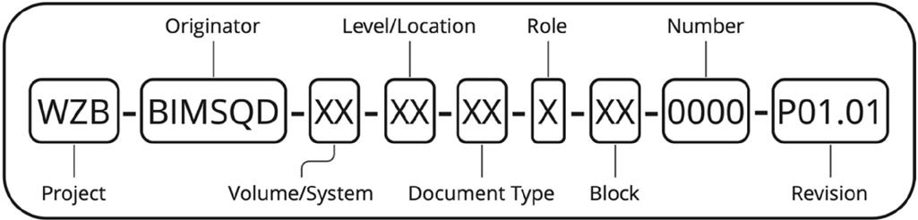
Naming Convention
A unique ID will be assigned to each information container based upon the documented convention that is composed of fields separated by a delimiter and assigned to attributes such as (1) block and (2) revision. An agreed and documented codification standard assigns a value to each field. Reference tables below.
The first field in the naming convention is the project code/ name, as already established in the EIR. In the second field, the originator of the information is specified, explicitly the organization (BIMSQUAD) that produced it. In the third and fourth fields, spatial subdivision of the project is shown starting with volume/system, representing disciplines, and moving to level/location, representing individual stories. Reference tables below.
OM
FM
SH
AF
BQ
CP
CL
CO
DR
PH
MI
TR
EP
FP
FR
DO
AM
XX
Naming Conventions
Code Volumn/ System ZZ All Volumes / Systems SI Site volume AV Architectural Volume SV Structural Volume MS Mechanical System ES Electrical System PS Plumbing System FS Fire System MF MEP+Fire System XX No Applicable Volumes / Systems Code Location/ Level ZZ All Levels / Locations 00 Ground Floor Level 01 First Floor Level 02 Second Floor Level 03 Third Floor Level 04 Fourth Floor Level 05 Fifth Floor Level 06 Sixth Floor Level 07 Seventh Floor Level 08 Eighth Floor Level 09 Ninth Floor Level B1 Basement Level 1 XX No Applicable Levels / Locations Code Document Type Description 2M 2D Model All discipline native 2D models 3M 3D Model All discipline native 3D models
Open BIM Model All discipline IFC models
Federated Model All disciplines combined model
Schedule Resource planning - 4D
Animation File Simulation video
Bill of Quantities Prepared for federated model
Cost Plan Estimation - 5D
Clash Report Clash detection / avoidance
COBie Asset management report
Drawing Report Drafting report using A1 Sheet
Photograph Any photographs
Meeting Minutes Minutes of meeting report
Team Review Report Sprint planning / Scrum retrospective
BEP BIM execution plan
FMT Presentation Final thesis presentation
FMT Report Thesis delivery report
Document Register Information control / Naming convention
AIM Asset information model
None Applicable -
The seventh through ninth fields in the naming represent the delivery block navigation aligned with the project life cycle, sequential file numbering and revision. Reference tables below.
An illustration of the naming convention, as outlined above, can be found below:
Code Role A Architect S Structural Engineer M Mechanical Engineer E Electrical Engineer P Plumbing Engineer F Fire Safety Engineer U BIM Manager V BIM Coordinator W Scrum Master Y MEP+Fire Engineer O Facility Manager X None Applicable
Revision
Work in Progress
Shared
Publihed
None Applicable Code Block Description
Block 1 BIM Management
Block 2 BIM for Design
Block 3 BIM for Construction
Block 4 BIM for Asset Management XX None Applicable Code Number Description 0101 Site Sequential numbering 0201 Architectural Sequential numbering 0401 Structural Sequential numbering 0601 MEP+F Sequential numbering 0901 Federation & Coordination Sequential numbering 1001 Managerial Sequential numbering XXXX None Applicable -
Code
P.01.01
P.01
C.01
XX
B1
B2
B3
B4
19 Naming Conventions
Clash Matrix
Clash Matrix
A clash matrix provides a convenient means of coordinating across disciplines and of making quick decisions about which elements of one discipline should be adapted to another in case of a clash. A coordination tool searches for collisions between models from various disciplines that have been federated into a single model.
Coordination tool is provided by the appointing party and is managed by the lead appointed party. Conflicts are assigned to discipline leads within each project group, who will be responsible for each clash.
Following a hierarchy of disciplines that occur chronologically during construction of the building, the disciplines are ranked by importance. Priority is given to architectural and structural models, followed by mechanical, plumbing, electrical, and firesafety systems.
A red alphabet indicates the discipline responsible for its internal coordination, as shown in the following table. The numerical order specifies the order in which clash detection occurs. Reference table below.

CLASH MATRIX Architectural Structural Mechanical Plumbing Electrical Fire Safety Architectural A 1 2 4 7 11 Structural B 3 5 8 12 Mechanical C 6 9 13 Plumbing D 10 14 Electrical E 15 Fire Safety F Architectural Structural Mechanical Plumbing Electrical Fire Safety Curtain wall Footing Air terminal Sanitory Light fixtures Hose reel cabinet Ceiling Column Duct segment Domestic Cable trays Fire alarm Door Beam Duct fitting Panel board Pipe segment Window Wall Pipe segment Lighting switch Pipe fitting Slab Pipe fitting Stair
3. 2. 1.
3.
IFC model files federated in BIMcollab ZOOM tool and synchronised to cloud for collaboration
1.
IFC model files federated in BIMcollab ZOOM tool and synchronised to cloud for collaboration
2.
IFC model files federated in BIMcollab ZOOM tool and synchronised to cloud for collaboration
Clash Matrix
Issues created upon clash detection with visual representation and description that includes naming, responsible party and priority


 4.
5.
6.
7.
4. Clash matrix defined to analyse clashes between different discipline models
4.
5.
6.
7.
4. Clash matrix defined to analyse clashes between different discipline models
5
Setting of source and target set rules between different disciplines to perform clash detection
6.
7. Imported BCF files from BIMcollab cloud to CDE platform for issue management by respective discipline leads
21 Clash Matrix
Visual Communication process map
SCRUM Retrospective
Scrum Retrospectives were collected on Slack chanel and meeting minutes for Phase 1, for delivery on Feb 20, 2022
Member Comments
Group two members In this exercise, we brainstormed our scrum retrospective in Slack, and then discussed the points in a daily scrum. Our findings can be found illustrated and described below.
Continue
Summarize references in format that can be inserted into documents when necessary.
Tidy the channels.
Stop
At the moment some channels are crowded with individual group noise.
Some large documents have been posted on channels that can be intimidating to go through with our time frames.
Invent
We can add channels for group work coordination eg. BIM Coordination/ Scrum Master board, Discipline Managers board. etc.
We need to test the time constrain if works for everyone:
We still need to discuss the severity level and time constrain during scrum planning. Act After each scrum meeting, our team shall discuss the following items to improve our agile process. What worked well? What could be improved? What will we commit to doing in the next scrum circle?
Mentor (from Meeting Minutes)
We gave a brief introduction of ourselves and of our projects to the mentor. Karol pointed out that the FMT will not be graded with each hand in, but the project will receive a cumulative grade at the end. This suggests:
The importance of Agile management and implementation. We have to make sure that our plans remain simple, well illustrated and easy to follow. Although details are not a priority, remember that processes need to be implemented to effectively coordinate.
It is important that we focus on efficient procedures. The details can be updated throughout the FMT as we build our knowledge. But good foundation protocols are very important. With each SCRUM retrospective, we should be able to suggest improvements that should be reflected in the final delivery.
It is important that each block of information is illustrated in each assignment, so that the final project can prove a complex understanding of the entire Master’s program.
It is important to keep things simple. Focus on accuracy/ precision over a final output. Each assignment should show a minimum of information delivered in lectures. Remember details can always be added.
Descriptive documentation. As we continue to present the Sprint Planning and other boards, remember to document a detailed description of the board design. Eg. Use legends to describe what colours, and labels mean.
FINALLY! Let’s try to enjoy the process. With the potential to revise and improve work throughout the FMT, don’t be too hard on yourselves. Work hard, be consistent and do your best! “Fighting!”
Think of the BIG picture. Think of BIMSQUAD as a startup company. With goals:
To add value to the owner/shareholder through BIM implementation, whether by saving money or time. The creation of automated templates and BIM processes to be improved and implemented in future projects. To improve communication with all parties and therefore make faster and better decisions. Etc. Why should a client choose BIMSquad over any other company?
SCRUM Retrospective
Summarize references in format that can be inserted into documents when necessary.
Tidy the channels. SLACK
At the moment some channels are crowded with individual group noise.
Stop
Posting large research references without attached summaries
Invent
How can we do things differently?
We can add channels for group work coordination
We need to test the time constrain if works for everyone:
We still need to discuss the severity level and time constrain during scrum planning.
What worked well/ could be improved? What we commit to doing in the next scrum cycle?
Act
What should we do next?
Use of agile retrospective template as judging criteria.
What help us back? Continue What help us move forward? 1.
Individually, reflect on what worked and you should continue doing and stop doing, Write down any ideas into the yellow section.
Reflect together
4 min per section 15 min together
Individually, rthink of next steps. Present and commit together.
4 min per section 10 min together
2. 23 SCRUM Retrospective


REVIT ARCHICAD TEKLA IFC
Solibri
BIM SYNC
SCRUM
BIM
COLLAB ZOOM BIM COLLAB BCF Design Process Workflow within openBIM
Retrospective
Design
Initial Setup
Phase 1
Pre- tender
Phase 2
Design
Secondary Setup
Phase 3
Pre- construction
Phase 4
Asset/ Opperations Management
Phase 5
Implementation
As per BIM Execution Plan (BEP), we are aimed to provide high quality of design and design documentation by implementing design authoring, design review and 3D coordination and virtual walk through.
Model Establishment and Publish
Discipline models have been created by two different design authoring tools (Revit and Archicad)
The WIP models have been saved and back up from the local drive and Cloud. ArchiCAD team has implemented the BIM cloud to achieve model work sharing. Revit team set up LAN server to achieve work-sharing Revit.
In the design process, the discipline models have been completed with all the modeling items as required according to EIR and BEP requirements. The native model and MVDs have been shared and published to the Bimsync CDE environment.
CDE and Model Coordination
In CDE, the BIMsync document folders have been created according to section 3.10 BEP. WIP>Shared>Review>Publish>Archive.
Reflecting on team correspondence feedback, extra training will be required. The lists of training items are listed below.
1. Model published to BIMsync, where the published IFC is in relationship with the document folder?
2. What is the correct model link procedure when discipline team member trying to link services model from BIMsync?
3. Can any models in the documents be published to CDE model viewer? What is the best practice procedure to be followed?
25 Design
Design Authoring Process
BIM dictionary defines the design authoring as “A Model Use representing the process of developing Generative Models or Parametric Models for design exploration, design communication and design iteration purposes. Design authoring is a key BIM activity leading to model-based 2D Documentation, 3D Detailing and other model-based deliverables.”
Description:
A process in which 3D software is used to develop a Building Information Model based on criteria that is important to the translation of the building’s design. Two groups of applications are at the core of BIM-based design process are design authoring tools and audit and analysis tools. Authoring tools create models while audit and analysis tools study or add to the richness of information in a model. Most audit and analysis tools can be used for Design Review and Engineering Analysis BIM Uses. Design authoring tools are the first step towards BIM and the key is connecting the 3D model with a powerful database of properties, quantities, means and methods, costs and schedules.


Process Overview:
Design authoring starts with identification of various models and their contents required by different disciplines as shown in the first two processes in the map. Next process is the development of an initial model by the architect for reference of all disciplines. Based on this, the disciplines can prepare their schematic models which will be reviewed in a workshop by all the stakeholders. The review will be resulted in acceptance or rework of the schematic models. On acceptance, the same models will be expanded to design development models by corresponding teams and another workshop for review will be carried out. On successful review, the models passes through the detailed documentation phase and final review will be carried out.
Services model filtering data as building stories (BIMCollab ZooM)
Services model filtering data as entities (BIMCollab ZooM)
Design Authoring Process
OpenBIM Design Process Workflow
This table describes the design process workflow within openBIM. This FMT used design authoring process from schematic design, to design development to construction documentation, and uses an openBIM workflow to allow interoperability and validation throughout the entire process.
Stage Process Description
1 Authoring Software (Schematic Design)
2 Interoperability Software (federation/ revision)

3 Authoring Software (design development)

Using desktop software, including Revit and ArchiCAD, the appointed party develops generative and parametric models in native file formats. Discipline managers are to refer to the Sprint Planning board to manage tasks within timelines and check models in accordance with ‘definition of ready’ and ‘definition of done’ specifications. In accordance with MVD specifications, the disciplines export required data for BIM uses in IFC format.
Using interoperability software, which includes BIMcollabZOOM, each discipline validates the IFC models against the federated model to review for possible data loss, data corruption, and incompatibility with defined specifications. The issue management information is exported as BFC to be corrected in authoring software (if necessary), before final models used in Design Development authoring, and uploaded to CDE platform.
Using desktop software, including Revit and ArchiCAD, the appointed party develops generative and parametric models in native file formats. Discipline managers are to refer to the Sprint Planning board to manage tasks within timelines and check models in accordance with ‘definition of ready’ and ‘definition of done’ specifications. In accordance with MVD specifications, the disciplines export required data for BIM uses in IFC format.
4 Interoperability Software (federation/ revision)


5 Authoring Software (construction documentation)


6 Interoperability Software (federation/ revision)
7 Cloud Software
Using interoperability software, which includes BIMcollabZOOM, each discipline validates the IFC models against the federated model to review for possible data loss, data corruption, and incompatibility with defined specifications. The issue management information is exported as BFC to be corrected in authoring software (if necessary), before final models used in Construction Documentation authoring, and uploaded to CDE platform.
Using desktop software, including Tekla, Revit and ArchiCAD, the appointed party develops detailed generative and parametric models in native file formats and prepares construction documentation for project handover. Discipline managers are to refer to the Sprint Planning board to manage tasks within timelines and check models in accordance with ‘definition of ready’ and ‘definition of done’ specifications. In accordance with MVD specifications, the disciplines export required data for BIM uses in IFC format.
Using interoperability software, which includes BIMcollabZOOM, each discipline validates the IFC models against the federated model to review for possible data loss, data corruption, and incompatibility with defined specifications. The issue management information is exported as BFC to be corrected in authoring software (if necessary), before final models uploading to CDE.
Using cloud software, which includes BIMSync, all disciplines upload IFC/BFC files to the CDE to create a federated model. The appointed party can run clash detection against all models and data in the federated model by deploying plug-in Solibri. Before BCF data is returned to authoring platforms for correction, team members and stakeholders can make cooperative decisions on improvements.
Design Authoring Process
27
Coordination Process Map
BIM Uses According to BEB
Parametric modeling content
BIM Uses According to BEB
SCHEMATIC DESIGN
Indentify model required Arch., Struc., MEP
Indentify content for model creation Arch., Struc., MEP
Develop Initial model
Arch. manager
Create schematic design Arch. model Arch. Create schematic design Struc. model
Arch.
Create schematic design MEP. model Arch. Upload schematic models to the CDE for model federation and preliminary coordination
Does this meet model requirements?
Refer to Trello’s User Story Map for Definition of Done (DoD) and Model acceptance criteria
Model validation and data checks
All Discipline
NO YES DESIGN PROCESS
REFERENCE INFORMATION INFORMATION EXCHANGE START
Program Model Preliminary Arch. model Arch Model MEP Model Struc. Model
Coordination Process Map
BIM Uses According to BEB
Does this meet model requirements?
Create detailed design MEP. model MEP. manager
Upload schematic models to the CDE for model federation and preliminary coordination
Refer to Trello’s User Story Map for Definition of Done (DoD) and Model acceptance criteria
Model validation and data checks
All Discipline
A map illustrating how multiple disciplines/parties cooperate to achieve common goals using information requirements can be seen below.
BIM Uses According to BEB
Does this meet model requirements?
Create construction design MEP. model MEP.
Upload schematic models to the CDE for model federation and preliminary coordination
Refer to Trello’s User Story Map for Definition of Done (DoD) and Model acceptance criteria
Model validation and data checks
All Discipline
NO NO YES YES
DESIGN DETAILED DESIGN END Arch Model Arch Model MEP Model MEP Model Struc. Model Struc. Model
Create construction
model Arch.
Create construction
model Struc..
CONSTRUCTION
Create detailed design Arch. model Arch. manager
design Arch.
Create detail design Struc. model Struc. manager
design Struc.
29 Coordination Process Map
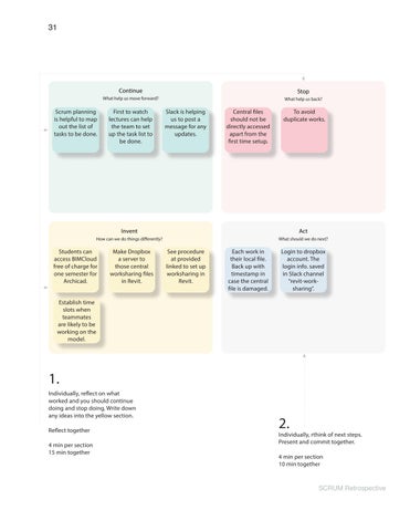
SCRUM Retrospective
Scrum Retrospectives were collected onSlack for phase 2, for delivery on June 5, 2022.
Member Comments
Group two members In this exercise, we brainstormed our scrum retrospective in Slack, and then discussed the points in a daily scrum. Our findings can be found illustrated and described below.
Continue Scrum planning is helpful to map out the list of tasks to be done.
If someone is ahead of watching the tutor recording, this person can help the team to set up the task list to be done.
Slack is helping us to post a message for any updates.
Stop Central files should not be directly accessed apart from the first time setup.
To avoid duplicate works.
Invent Students can access BIMCloud free of charge for one semester (plus one semester if it is a yearlong project).
The methodology for the model work sharing is to make Dropbox a server to those central files.
Set up procedure is in the link below: http://therevitkid.blogspot.com/2012/01/using-dropbox-asrevit-server-free.html
Act When signing up, you will be asked to read and accept their Terms and Conditions.
Login to dropbox account. The login information has been saved in the Slack channel called “revitwork-sharing”.
Everyone shall work in their local file. Back up with timestamp in case the central file is damaged.w Mentor (from Meeting Minutes) Included above. Karol helped Archicad team set up worksharing with Graphisoft.
SCRUM Retrospective
Continue
Stop
What help us back?
Scrum planning is helpful to map out the list of tasks to be done.
First to watch lectures can help the team to set up the task list to be done.
Slack is helping us to post a message for any updates.
Central files should not be directly accessed apart from the first time setup.
To avoid duplicate works.
Invent
How can we do things differently?
Students can access BIMCloud free of charge for one semester for Archicad.
Establish time slots when teammates are likely to be working on the model.
Make Dropbox a server to those central worksharing files in Revit.
What help us move forward? 1.
Individually, reflect on what worked and you should continue doing and stop doing, Write down any ideas into the yellow section.
Reflect together
4 min per section 15 min together
See procedure at provided linked to set up worksharing in Revit.
Act
What should we do next?
Each work in their local file. Back up with timestamp in case the central file is damaged.
Login to dropbox account. The login info. saved in Slack channel “revit-worksharing”.
Individually, rthink of next steps. Present and commit together.
4 min per section 10 min together
2. 31 SCRUM Retrospective


IFC MVD BCF Coordination Process Map 1 AUTHORING SOFTWARE 2 REVIEW SOFTWARE 3 CLOUD SOFTWARE
SCRUM Retrospective
Pre-construction
Initial Setup
Phase 1
Pre- tender
Phase 2
Design
Secondary Setup
Phase 3
Pre- construction
Phase 4
Asset/ Opperations Management
Phase 5
Implementation
During the pre-construction phase, 3D and 4D modeling techniques can be used to simulate the construction process through a BIM model and detect operation succession errors and space use conflicts
The pre-construction phase was broadly classified into three phases:
1. Developing BIM models: Developing Architectural, Structural, and MEPF BIM models from the designs created by the architects and engineers. This phase commenced with the development of an Architectural model based on architect’s design. Structural model was created from structural engineers’ design. These two models were copied to the MEPF plan and served as a reference for creating MEPF models with design inputs from HVAC, Electrical, Plumbing, and Fire Fighting designers.
2. Clash Detection and BIM Coordination: Performing interdisciplinary interference check and clash resolution to generate coordinated architectural, structural, and MEPF models. Since architectural and structural models were developed before routing the MEP Services it helped in reducing clashes. The remaining clashes were detected and resolved in close coordination with all the relevant design teams.
3. Extracting 2D Drawings: Extracting Architectural Construction Drawings and MEPF Shop Drawings from the coordinated models. During the final phase, 2D drawings were extracted from the final models. These drawings were directly used on-site for the purpose of construction.
The use of BIM in the pre-construction process enhanced the construction speed while minimizing the costs. This approach was more environment-friendly as on-site re-work and subsequent wastage of materials was reduced.
Benefits of BIM during the pre-construction
In pre-construction, BIM can serve as a tool to facilitate straightforward operation in all phases of the project, including construction management, pre-construction planning, and post-construction management to empower the facilities management function.
The 3D BIM Model has helped to resolve issues, for example, BIM Coordination Services and Constructability to eliminate additional costs or rework that result in a delay.
BIM can enhance communication and visualization in the pre-construction period. BIM can improve cost estimation, scheduling of construction management, design and planning optimization, construction and fabrication, quality control, waste and time management.
33 Pre-construction
Common Data Environment (CDE) Workflow
Coordination describes the requirements and protocols for information exchange among project parties and across collaboration platforms such as authoring software, revision software, and coordination CDE platforms. Below are a list of Common Data Environment (CDE) checklists to perform at information delivery milestone, in accordance with information exchange requirements:
1. Has any project-specific expansion of the standard status codes and revision system been defined?
2. Has a classification system been defined?
3. Has an information container ID codification standard been defined?
4. Does the codification standard define how model renditions/exports are to be given different container names?
5. Have all the potential CDE solutions been reviewed?
6. Have security considerations been considered when
Plugin allows users to view BCF issues in authoring software
selecting the potential CDE solution(s)?
7. IF many CDE used, have they been implemented in a collaborative manner and workflow?
8. Has any particular testing been done?
9. Is there agreement on how information containers will be transferred between solutions?
10. Has a clear CDE workflow been implemented?
11. Has the project got a clear documented set of standard methods and procedures of how metadata is assigned?
12. Is it working with tables/classification systems?
13. Has it been confirmed what each status code means?
14. Has rules been confirmed?
15. Has it been made clear how each metadata assignment is made in CDE?
WIP Model reuploaded to CDE under correct revision under “Documents”
1. Most current
2. Used mainly for issue
3.
Coordination Process Map for CDE Environments
MODEL Revit, ArchiCAD, Tekla WIP model Shared model Documents Models BIM Collab IFC Models Published model BIM Sync BIM Sync MVD Model Summary: GBIM_BIMSQUAD_ARCH_MODEL GBIM_BIMSQUAD_STRT_MODEL GBIM_BIMSQUAD_FIRE_MODEL GBIM_BIMSQUAD_HVAC_MODEL GBIM_BIMSQUAD_PLUB_MODEL GBIM_BIMSQUAD_ELEC_MODEL
BIM model exported as BCF
NATIVE
Federated
as BCF
Clash issues to be identified and grouped before export
BIM Manager to be notified
BIM Manager to be notified
IFC
management
Upload via plugin by discipline lead Export as MVD
Upload IFC model to “Models” from CDE
Native File rvt., pln Native File IFC Native File IFC
Common Data Environment (CDE)
Workflow
OpenBIM Cordination Workflow
This table describes the phases of the coordination workflow used in the Pre-construction phase.
Stage Process Description
1 Authoring Software The appointed party develops generative and parametric models using desktop software, such as Revit, ArchiCAD, and Tekla. According to MVD specifications, disciplines export required data for BIM use in IFC format in order to visually validate and comment on issue management in validation software.
2 Review Software IFC models are validated by disciplines and uploaded to CDE (BIMSync) to be approved by the BIM manager. Collection of discipline models are then federated and clash detection performed with a clash matrix in BIM Collab. Issue management delegates issues to be managed by discipline managers and issues are exported as a BFC to CDE to be referenced by all parties.

3 Cloud Software All parties can access BCF issue management tracking and perform additional issue tracking on the CDE platform. Information exchange requirements are specified in the BEP, and are typically delivered at information delivery milestones. By downloading the BIMSync Revit plugin, disciplines can access and manage issue tracking data from proprietary software Revit. Once issues have been addressed discipline can issue comments and change the status of the issue. Once all issues have been resolved, members can export edited IFC from the plugin directly into BIMSync.
4 Repeat Until all exchange information requirements have been met, the exchange of information is repeated. It is possible to simplify the process by using plugins such as the BIMSync Revit plug.


35 Common Data Environment (CDE) Workflow
Visual Communication
Visual Communication
Objective: Model use where 3D models generated/ enhanced for the purpose of communicating visual, spatial and functional qualities through renders, animations and standalone presentations.
VR-enabled walkthroughs and high-quality rendered images have proven to be valuable in current AEC industries. Today, 3D visualization is a major component of marketing presentations and business meetings.

Twinmotion
For the purpose of this FMT we have chosen to use Twinmotion as our AR tool of choice. A large asset library is available in the software. Twinmotion can be linked to Design authoring software using the Datasmith Exporter plugin. Using the Datasmith plugin, we can change the original model and sync

3)
Assign
Tools/ software: Twinmotion
1)
Export federated IFC to datasmith format to be uploaded to Twinmotion
2)
textures, environmental conditions and contextual models to convey relevant context
Import Model Generate Context Establish Narative
Sets frames and paths for images, videos and panoramas
3D Visualization graphics developed in Twinmotion Workspace
Visual Communication
updates into Twinmotion. During the design process for the Wezig building, we created a project environment, illustrating details such as landscape, surrounding buildings, characters, and vehicle paths. As the project evolved from design to construction, we synced Twinmotion with the latest model and completed the interior design. As part of the rendering process, Twinmotion provides numerous options for lighting and environmental conditions. Video and images produced by Twinmotion can be very realistic when using the correct hardware capabilities.

4) Export presentation file or export presentation to cloud Visual Communication process map
Export Media
37 Visual Communication
Images, videos and presentations exported to Twinmotion Cloud
Construction Scheduling
Construction Scheduling
Objective: Use ‘time’ as a parameter to simulate the construction sequence, and model elements driven by activities/ tasks defined within a construction. Visually represent planning data via gantt charts and construction animation.

Tools/ Software: Synchro
Construction sites must analyze waste and time/value as part of lean construction. In order to implement 4D BIM planning into our Weizig building project, we are integrating MS project into SYNCHRO Pro 4D BIM management software.
It brings enormous benefits in terms of Safety and efficiency.
1. To optimize the project plan, constructors look at the project from multiple perspectives
2. To avoid time waste and resource shortages by analyzing the construction sequence and buildability.
3. Quickly determine the critical path of the changes and their impact
4. A high degree of transparency in communication.
Import Model Manage Resources
Manage Tasks
4) Assign Tasks
1) Import IFC model
Construction Scheduling
2) Assign resources (equipment, humans, materials, companies, model elements)
3) Manage resources ( add appearance profiles, set calendar detailed, add activity codes etc.)
5) Assign resources to tasks
6) Set duration/ key dates
7) Assign costs
8)
4D linking ( link task along timeline)
Assign and manage resources
The Process included
1. By managing 3D and 2D resources, we simplify resource structure and make 4D scheduling and linking easier.
2. Based on the LOD of the BIM models, we detailed the WBS.
3. In the BIM model, we identify any valuable metadata and match resources to tasks.

4. The tasks require importing equipment and creating equipment resources.
5. It is possible to customize the labor rate for each task or for the project as a whole.
Considerations for Synchro Pro
Utilizing the shortcut in Synchro Pro will increase productivity and task performance, For example:
1. Use shortcuts e.g Control +Shift+ S = Isolation View; Ctrl+Shift+A=Assign the resource to the task
2. Move the time bar before data time. Isolated by level. Use visibility to identify which one has been assigned to the tasks, vice versa
3. Customize current or create new appearance profile to any particular items to match construction methodology
4. Grouping Resource will treat multiple single items to be treated as one items
Manage Sequence Manage Media 9) Visually manage and test sequence on gantt chart 11) Export construction animation. 10) Assign custom filters for trades to access planning content. Construction Scheduling process map Visually manage sequence on gantt chart 39 Construction Scheduling


showing components
Legend
WeZig Section B
WeZig Section A
Construction Scheduling

41
WeZig Construction animation being set up for export
Construction Scheduling
Cost Estimation
COST ESTIMATION
Objective:
Model use representing how 3D models are used to generate feasibility studies and compare different budgetary options.
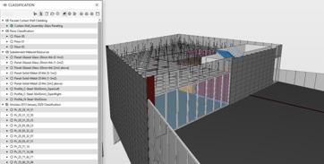
Tools and software: Excel, Solibri
In the FMT WeZig Building BIM delivery, we have included 5D Cost estimation to assist the project QS in generating a schedule of quantity in order to optimize billing and costing. The workflow is detailed below.
1. Real Time Conceptual modeling with Quantity take off Comparison
Our team implemented a simple virtual dashboard for comparing each design phase model and highlighting the differences and changes. Below is a screenshot illustrating this.
Import Model Requirements
Assign classification
1)
Receive client MDR requirements
2)
Import IFC into Solibri
3) Use classification manager to match MDR
Import IFC into Solibri and match MDR
Estimation
Cost
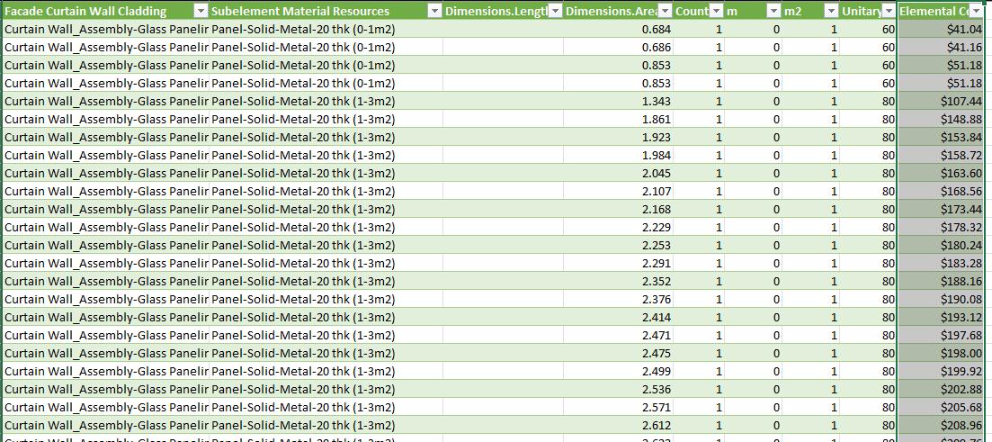
2. Quantity extraction to support detailed cost estimates
Our team can provide schedules of quantity for each trade or scope that requires QS to assist in budget estimation and cost planning.
The metadata can flow between design authoring software and Excel in closed BIM, using Archicad or Revit as leading streams design software.
Using OpenBIM, we can generate quantity schedules using Excel when we receive the Material Resource Database (MRD) schedule from the client. Below is a flowchart of the workflow process.
Generate takeoff Export for use
6) Create PivotChart table
5)
Quantification takeoff with current classification mapping procedure
7) Create filter and selection in Excel
Cost Estimation process map
The image below to present the IFC model metadata with correct IFC/ client required naming convention. 43 Cost Estimation
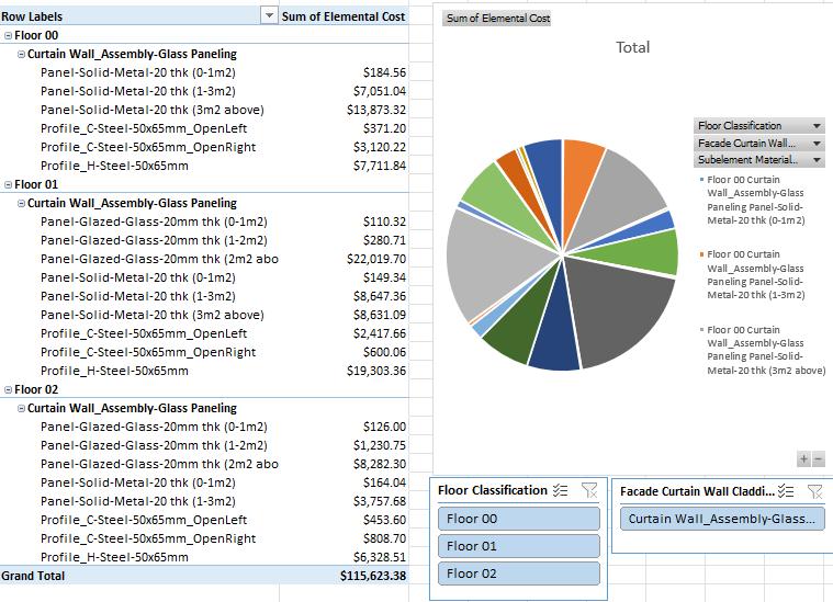
Above is an example of openBIM implementation cost output in Excel Cost Estimation
Power BI Workspace 45 Cost Estimation
Energy Analysis
Energy Analysis
Objective: Model use and building performance metric measuring how and how-much a facility consumes energy, that has been generated to improve the sustainability and performance of facility design.
Tools/ Software: Revit, Insight and Green Building Studios
Energy analysis (Utilization) is defined by BIM Dictionary as “A Model Use and a Building Performance metric measuring how and how-much a Facility consumes energy. High-performance buildings typically consume less energy (electricity for lighting, fossil fuels for heating, etc…) than other comparable buildings”
An energy analysis of the project was performed using BIMbased simulations such as Revit, Insight, and Green Building Studio. Retrofitting strategies were used to study the energy performance and thermal comfort of an existing building and reduce the reliance on the mechanical system. As a result of BIM tools, designers were able to experiment with various design solutions prior to executing the final design, saving the firm both money and time, while also contributing to more energyefficient buildings.
Performing Energy Analysis
Having a thorough understanding of energy consumption and improving building efficiency is crucial for reducing energy consumption. Building envelope design measures, as well as performance in humid and hot climates, are unknown at this time.
Inputs for Energy Model Generation in Revit
Revit collects weather data and sun path information from the local weather station according to location.
1. Identifying the project’s location as well as the weather station’s location.
2. Heating design temperature:~ 21℃
Energy Setting Inputs
To conduct an energy simulation, the energy model uses the information generated by Revit for walls, doors, roofs, windows, and floors.
3)
Generate energy models (in Revit)
a) Weather data and sun path information (from weather station)
b) Energy settings for walls, doors, roofs, windows and floors (generated from Revit)
c) Advanced energy settings (e.g. material thermal properties (conceptual and analytical types)
Energy Analysis
Import Model Manage Settings Generate model
IFC into Revit
1) Import
energy settings
2) Input
Energy settings in Revit. Advanced Energy Setting Inputs


Energy settings affect the creation of energy models. Furthermore, they can be used to specify material properties and thermal properties within the Revit model, which may be used optionally.
Material Thermal Properties: Conceptual Types
Different components of the building, such as walls, roofs, ceilings, slabs, floors, and windows, have different thermal inputs that can affect the building’s heating and cooling loads. Material Thermal Properties: Conceptual Types
Material Thermal Properties: Analytical Types
Generate report Establish strategy
4) Create report from Green Building Studio
Energy-Saving Strategies
1. Building orientation
2. Window shades
3. Window-to-wall ratio
4. Window glazing
5) Establish Energy-saving strategies
5. Wall construction helps in reducing heat loss and heat gain
6. Lighting efficiency—average internal heat gain and power consumption of electrical lighting per unit floor area is lower based on the reduced usage of lighting during the day which is attained by proper availability of daylight.
Energy Analysis process map 47 Energy Analysis
Summary Result
A report from Green Building Studio provides information about the amount of energy and electricity consumed by various factors, including area light, external usage, miscellaneous equipment, space cooling, vent fans, pump backup, and hot water use.
Results and Inferences
Results and Inferences
Efficiency factors achieved through window-to-wall ratios and efficiency factors achieved through window shades.
Energy-Saving Strategies
1. Building orientation
2. Window shades
3. Window-to-wall ratio
4. Window glazing
Energy Analysis

5. Wall construction helps in reducing heat loss and heat gain
6. Lighting efficiency—average internal heat gain and power consumption of electrical lighting per unit floor area is lower based on the reduced usage of lighting during the day which is attained by proper availability of daylight.
7. The efficiency in daylighting an occupancy control can be achieved by usage of advancement in technology for daylight dimming and occupancy sensor system.
8. Panel efficiency which is attained by the percentage of the sun’s energy that will be converted to AC energy. Higher efficiency panels cost more, but they produce more energy for the same floor area.
Energy analysis output
Conclusion
There are several factors which contribute to energy consumption in the building, including:
less energy benefits.
The study highlights the need to reduce the heat gain through the building envelope and improve thermal comfort. Based on the simulation results, façade designs can be used to control insulation efficiently, maintain a satisfying indoor environment, reduce energy demand, and support and consolidate architectural visions while contributing to energy reduction.

Using appropriate technology for designing the building envelope can help reduce these energy consumption factors. The building envelope plays a significant role in how much energy is consumed in a building. According to simulation results, proper shading devices and window glass are effective in reducing energy consumption, while roof construction shows
An important factor to consider while designing a building is the envelope’s impact on the amount of energy needed to heat and cool a building. The envelope should be optimized in order to reduce the amount of energy required for heating and cooling.
1. Building orientation
2. Window shades
3. Window-to-wall ratio
4. Window glass
5. Wall construction
6. Roof construction
7. Lighting efficiency
Energy analysis output 49 Energy Analysis
Energy models
The energy model is generated by Revit from inputs such as location, weather, and thermal properties and transmitted to Insight in the form of color codes for different components.
Energy Analysis
 Energy models
Revit 1. Set Site Location and Building Type 2. Use Conceptual Model or Building Design 3.Focus on optimizing form and orientation on openings, shades and exterior surface
Insight Simulate changes to: 1. Window-to-Wall Ratio 2. Orientation on Site 3. Thermal Performance of Envelop
Revit Refine building Quick and iterative decisions on sustainable design options
Insight 1.Compare building designs 2. Create categories 3. Adjust widgets across building designs 4. Determine changes to meet set target
Revit 1. Apply load reduction strategies from Insight 2. Generate heat and cooling load reports 3. Analyze and optimize iteratively
Insight 1. Analyze heating and cooling loads 2. Calculate EUI and Annual costs 3. Develop load reduction strategies
Revit 1. Select HVAC systems 2. Refine Building and Space type setting
Insight 1. Focus on HVAC Systems Widget 2. Evaluate impact on EUI/cost
Revit 1. Accurately model building elements 2. Apply Energy Analysis Properties to Spaces
Insight Ongoing analysis
Revit Ongoing Analysis and Optimization
Insight 1. Optimize building energy use 2. Test more variables and Save scenarios
Revit 1. Cost/Benefit Analysis 2. Client Engagement
Insight 1. Analyze design decisions 2. Mitigate increases in up-front costs with reduction in annual energy cost
1. Simple Box Modeling
2. Conceptual Design Modeling
3. Load Reduction Modeling
4. HVAC System Selection Modeling
5. Design Refinement
6. Design Integration and Optimization
ENERGY ANALYSIS Energy Analysis Process 51 Energy Analysis
7. Energy Simulation Aided Value Engineering
Structural Analysis
Structural Analysis
Objective: Analyze the behavior of structural systems, including the static and dynamic loads on building and how building design can be subsequently optimized.
Tools/ Software: SCIA Engineer
BIM USE: Structural Analysis Interoperability Tool Using SCIA Engineer 21


SCIA Engineer is one of the first structural analysis software applications to be certified for both import and export of IFC 2x3. An Open BIM workflow for structural analysis is made easier with its special BIM toolbox. It enhances project efficiency and stakeholder collaboration by reducing manual tasks and adapting to any workflow. Open BIM is made possible by a fundamental component, the IFC format, one of many formats that SCIA Engineer supports. To create the Model View Definition (MVD) needed for this work, a new 3D view was created in Revit Structure 2021 and named SCIA Model. The view ensured that all structural elements of the building were visible for the analysis. A 2x3 Coordination 2.0 Schema was then used to export this view to the IFC. As part of the export process, all structural elements are properly defined and exported in accordance with their respective IfcName.
Insert image
A material table in .CON format was created for converting the structural elements’ materials from Revit to SCIA Engineer Material. All existing materials have been mapped to C25/30. A reference model of the ifc model was then imported into SCIA.
Import Model Manage Settings
Assign settings
1)
Import structural IFC generated from Revit
Structural Analysis
2) Map structural elements/ materials to SCIA recognized values
3) Convert solid element to ID and 2D SCIA elements
4)
Assign resistance ratings to structural elements
5)
Assign load bearing status to structural elements
Convert Ref. Model to 1D & 2D.
Mapping of Revit Element and Material to SCIA Engineer’s
Solid elements had to be converted to 1D and 2D SCIA elements using the BIM Toolbox tool since the reference model import type was used. During the conversion process, structural columns and beams were converted to 1D elements, and walls and slabs were transformed into 2D elements.
This BIM toolbox alignment tool ensured that the converted 1D and 2D elements were connected correctly.

6)
Calculate/ Analyze internal forces and deformation of the structural elements
7)

report Export for use
Export structural model to Tekla (with IFC 2x3 CV2.0)
Generate
Structural Analysis process map Generated Analytical Model 53 Structural Analysis
All existing column sections and their materials were modified to HEB300 and S275 respectively. In addition, all structural elements were assigned a fire rating of R60, and their load bearing status was confirmed as activated.
Structural Analysis

Create Supports, Apply Loads, Analyse Frame
The 1D and 2D elements now have a fixed support type; load groups and load cases (self-weight) have been created; and all 2D elements have been meshed. The ‘Calculate’ button was selected to analyze internal forces and deformation of the structural elements.
As a result of structural analysis of the building frame and design of structural elements, the structural model was exported in Tekla Structures to ifc 2x3 CV2.0 schema for the creation of reinforcement detail drawings and steel fabrication drawings.`


Verify Member properties 55 Structural Analysis
SCRUM Retrospective
Scrum Retrospectives were collected on Slack and meeting minutes for Phase 3, for delivery on August 28, 2022.
Member Comments
Group two members In this exercise, we brainstormed our scrum retrospective in Slack, and then discussed the points in a daily scrum. Our findings can be found illustrated and described below.
Continue Validation and Issue tracking
Update folder organization on CDE to work in progress, published, shared and archived as per lecture notes.
We have updated the Sprint planning to reflect what needs to be developed for the FMT Stop
Do not move as a zip into BIM Sync.
Invent
Plan to resolve a detailed issue management and clash detection process , and implement a better collaboration workflow.
Once we have finalized the issue management and clash detection we need to update our collaboration workflow.
Act There were some issues with M8/units 4 and 5, and as a result there was some confusion on how to proceed with our validation and clash detection for our discipline model.
Organize daily scrums to catch up with requirement deliverables.
Mentor (from Meeting Minutes)
Instal BIMCollab/ (BCF Managers):
One person checks clashes. Exports packages as BCF. Import issues to BIMSync.
OPTION 1
Install BCF managers into proprietary software. Can also use BIM Collab Zoom for issue report. All issues should be transferred to BIM Sync. Create rule sets and smart views. Perform issue management. Move at the end of the coordination to close the data flow in order to close the cycle. Visually validate models on BIM Sync, and add any associated documents
OPTION 2
Do visual checks in Solibri/ BIM Collab. NB. Solibri has built in tools where you can create rule sets and instantly move into BIM Sync. In BIM Sync @ right hand corner (RED circle) there is BCF manager plugin. Solibri can check escape zones, accessibility and building code accommodations COORDINATION
Deliver all models to specific space. Check models (download models or reap from plugins) for seamless issue management. Check models 2 for BCF and IFC for rules e.g don’t delete elements, edit instead. Check BIM uses. In BIM Sync you can link objects e.g warranty cards and relevant information.
BIM Sync PLUGIN
Choose the read files for submission. Can always update in backlogs
If we have a problem handling IFC models, try IFC optimizer by Solibri -like WINZIP, can delete empty containers. Focus on optimizing geometry and not the data. Will be filled by you in the future
SCRUM Retrospective
Validation and Issue tracking Update folder organization on CDE to WIP, published, shared, archived
We updated the Sprint planning to reflect what needs to be developed for the FMT
Stop
Invent
How can we do things differently?
Plan to resolve a detailed issue management and clash detection process
Plan to implement a better collaboration workflow
We need to update our collaboration workflow and process maps
Do not move as a zip into BIM Sync
Act
What should we do next?
Resolve confusion around M8/units 4/ 5.
What help us back? Continue What help us move forward? 1.
Research how to proceed with our validation and clash detection for our discipline model.
Organize daily scrums to catch up with requirement deliverables
Individually, reflect on what worked and you should continue doing and stop doing, Write down any ideas into the yellow section.
Reflect together
4 min per section 15 min together
Individually, rthink of next steps. Present and commit together.
4 min per section 10 min together
2. 57 SCRUM Retrospective


Final Imported contact details Final Imported component information
SCRUM Retrospective
Asset/ Operations Management
Initial Setup
Phase 1
Pre- tender
Phase 2
Design
Secondary Setup
Phase 3
Pre- construction
Phase 4
Asset/ Opperations Management
Phase 5
Implementation
In complying with ISO 19650-3: Operational Phase of Asset Lifecycle, building information modeling (BIM) is required during the operational phase. In particular, asset management encompasses all aspects of asset life cycles, including operational phases. During the operation phase, routine inspections, maintenance, and replacement of minor components of the assets continually result in minor modifications.
According to RIBA’s Plan of Work 2020, 7D BIM involves feeding building models with information and data needed for asset life cycle usage. After handover, this stage ensures that the building is used, maintained, and operated efficiently throughout the entire asset lifecycle. This information can be assessed and managed through COBie - Construction, Operations Building Information Exchange.
COBie - Construction, Operations BuildingInformation Exchange.
COBie is a non-proprietary data format for the publication of a subset of building information models (BIM) focused on delivering asset data as distinct from geometric information (theNBS.com).
As opposed to the traditional way of keeping typical construction project information in drawings, BOQ, schedule, technical data sheet and specification for different project disciplines, COBie format ensures that key project information needed for the operational phase of the asset is pulled into one format. The client’s AIR and EIR require all project stakeholders to contribute to the information domicile. Using the Asset Information Model, this information is extracted into a spreadsheet.

1. Update member contact details 59 Asset/ Operations Management
2. COBIE related detail updating in each asset of the model
3. Update project information related to COBIE in Model

 Asset/ Operations Management


 5. Space/zone manger to select adjust area/zone details in Model
4. Parameter mapping to produce final spread sheet with COBIE info.
5. Space/zone manger to select adjust area/zone details in Model
4. Parameter mapping to produce final spread sheet with COBIE info.
61 Asset/ Operations Management
6. Final DATA selection for spreadsheet
Asset Information Management
BIM dictionary defines an Asset Information Model (AIM) as an “Information Model relating to the Operational Phase” ISO 19650-1 (3.3.9). The Asset Information Model (AIM) supports the maintenance, management, and operation of an Asset throughout its Asset Life Cycle. AIM can act (i) as a repository for all Asset Information; (ii) as a means to access/link to enterprise systems (e.g. CMMS and BMS); and (iii) as a means to receive and centralize information from other Project Participants throughout Project Lifecycle Phase
Power BI
Considerations
By utilizing BIM tools such as IFC viewers and Speckle, Power Bi can be used to enhanse to openBIM proces. The platform can be used to extract and illustrate information from IFC models. Below are some of openBIM considerations for Power BI use:
Integrating IFC viewer into virtual dashboard
To integrate an IFC viewer into a virtual Dashboard: Try to minimize grouping objects.

Whenever possible, minimize the number of objects grouped when using an IFC viewer in a virtual dashboard. The size of the model will significantly increase if each tile is modeled with a curtain panel.
When IFC viewer is included in the virtual dashboard, a plain wall with correct layer management would work smoothly
IFC Viewer - Speckle
PowerBi and IFCs can be connected using an open source platform.
Model content should be relatively light to prevent the input process from taking too long. It would be better to have a public stream. The development team is utilizing the viewer through a private stream.
The following pages show examples.
2D Products information Client Requirements Structural column Floor Structure Archtiecture MVDs Services Structural bean Steel work Floor finishes Wall finishes Ceiling finishes Curtain wall & panelling Roof buildup Door and windows Door and windows Room data Electrical devices and fittings Services equipment Pipework Air terminal
AIM Process Map Asset Information Management


Discipline data dashboards Room data dashboards Virtual Dashboard 3D Data Speckle/ IFC tracker Excel Power BI 2D Data Power BI Desktop IFC Elements IfcMember IfcPlate IfcOpeningElem… IfcDoor IfcFlowTerminal IfcSlab IfcStairFlight IfcRailing IfcStair IfcBuilding IfcBuildingElem… IfcProject 1.0K 0.3K 0.1K 0.0K 0.0K 0.0K IFC Document Info Sum of FileBytes IFC Element Category Select all (Blank) IfcBuilding IfcBuildingStorey IfcDoor Object Properties PropertySet Project Address Half Oval Short Axis Length Half Oval Long Axis Length Half Lavatory Length Family Family and Type Type Project Number Project Name Analytical Properties Absorptance Roughness Thermal Mass Define Thermal Properties by Solar Heat Gain Coefficient Visual Light Transmittance Thermal Resistance (R) Heat Transfer Coefficient (U) Analytic Construction Base Offset Elevation -City, State Zip 0.203 0.2415 Stair Stair Curtain Wall: Curtain_Wall_T1EiPM_XC_BIM_Model Project Name Schematic Type 0.319619227 Wood frame, double glass Analytical Properties Analytical Properties(Type) Calculation Rules(Type) Constraints Constraints(Type) Construction Construction(Type) Dimensions Dimensions(Type) Graphics Graphics(Type) Handrail1(Type) WeZig Building Architectural Asset Model ower BI Desktop IFC Elements oj N of FC W - M Q -R IFC Element Category oj S Object Properties Fi O y P _B C q C _S oj PropertySet O _A S _B C _P od _S C WeZig Build ng Architectural Asset Model AIM Process Map 2 63 Asset Information Management

Power BI Desktop First Value ## Street-City, State Zip 0 0.199825 0.203 0.238325 0.2415 0.315 Basic Wall Cast-In-Place Stair: Monolithic Stair Cast-In-Place Stair: Monolithic Stair Cast-In-Place Stair: Monolithic Stair Cast-In-Place Stair: Monolithic Stair Ceilings Curtain Wall: Curtain_Wall_T1General facade zone EiPM_XC_BIM_Model Issue Date Owner Project Status Project Name <None> 0.1 0.239005736 1 2.273913043 35.09644594 Schematic Type 0 0 0.319619227 3.128722913 Schematic Type Wood frame, double glass door 0 0 0 0 0 0 First Name by Name and Mesh WeZig Building Architectural Asset Model WeZig Building Architectural Asset Management
Information Management
Asset
PropertySet
Analytical Properties
Analytical Properties(Type)
Calculation Rules(Type)
Constraints
Constraints(Type)
Construction
Construction(Type)
Dimensions
Dimensions(Type)
Graphics
Graphics(Type)
Handrail1(Type)
1.1.02 IFC Elements 0K 2K IfcMember IfcPlate IfcBeam IfcOpeningElem… IfcWallStandard… IfcColumn IfcDistributionP… IfcDoor IfcFlowTerminal IfcSlab IfcCurtainWall IfcStairFlight IfcRailing IfcCovering IfcBuildingStorey IfcStair IfcBuilding IfcBuildingElem… IfcProject IfcSite 2.3K 1.0K 0.3K 0.2K 0.2K 0.2K 0.1K 0.1K 0.1K 0.0K 0.0K 0.0K 0.0K 0.0K 0.0K 0.0K 0.0K 0.0K 0.0K 0.0K
Name Sum of FileBytes IFCVersion Crea WZB-BIMSQD-Architecture.ifc 78,332,884.00 Ifc2X3 21.1 IFC Element Category Select all (Blank) IfcBeam IfcBuilding IfcBuildingElementProxy IfcBuildingStorey IfcColumn IfcCovering IfcCurtainWall IfcDistributionPort IfcDoor Object Properties PropertySet First Value Other Project Address Elevation Half Oval Short Axis Length 1 Half Oval Short Axis Length Half Oval Long Axis Length 1 Half Oval Long Axis Length Half Lavatory Length Family Name Family Family and Type Type Type Id Category Host Id Project Number Project Issue Date Client Name Project Status Project Name Analytical Properties Analytic Construction Absorptance Thermal Resistance (R) Roughness Heat Transfer Coefficient (U) Thermal Mass Define Thermal Properties by Analytical Properties(Type) Solar Heat Gain Coefficient Visual Light Transmittance Thermal Resistance (R) Heat Transfer Coefficient (U) Define Thermal Properties by Analytic Construction Constraints Angle Base Offset Default Elevation Elevation Elevation from Level OffsetfromHost ## Street-City, State Zip 0 0.199825 0.203 0.238325 0.2415 0.315 Basic Wall Cast-In-Place Stair: Monolithic Stair Cast-In-Place Stair: Monolithic Stair Cast-In-Place Stair: Monolithic Stair Cast-In-Place Stair: Monolithic Stair Ceilings Curtain Wall: Curtain_Wall_T1General facade zone EiPM_XC_BIM_Model Issue Date Owner Project Status Project Name <None> 0.1 0.239005736 1 2.273913043 35.09644594 Schematic Type 0 0 0.319619227 3.128722913 Schematic Type Wood frame, double glass door 0 0 0 0 0 0
IFC Document Info
First Name by Name 65
Information Management
Asset

WeZig Building Services Asset Management Power BI Desktop First Value Elevation Justification Number magiProductFamilyId Diameter 1 <not associated> <not associated> 0 0 0 0 0 0 00 Ground Floor Level 00 Ground Floor Level 00 Ground Floor Level -10068.4 -10131.59988 -10131.59988 Center Middle © Progman Oy, all rights reserved 1 1" 202 23.45.05.14.14 3 Adjusting/Controlling Valves for Liquid Services DLQ-AK-*-*/* DLQ-AK-M-L/400 DLQ-AK-M-L/400 Fire Discipline Use Square ceiling diffusers, flush mounting, plenum box TROX 0 0 0 0 0 0 0 0 0.0001001 0.000922031 0.6 0.6 Circuiting Lighting WeZig Building Services Asset Model
Information Management
Asset
IFC Elements 0K 10K IfcDistributionP… IfcFlowFitting IfcFlowSegment IfcFlowTerminal IfcFlowController IfcDistributionC… IfcSystem IfcBuildingStorey IfcBuilding IfcProject IfcSite 10K 2K 2K 1K 0K 0K 0K 0K 0K 0K 0K IFC Document Info Name Sum of FileBytes IFCVersion Crea WZB-BIMSQD-Services.ifc 63,004,243.00 Ifc2X3 21.1 IFC Element Category Select all (Blank) IfcBuilding IfcBuildingStorey IfcDistributionControlElement IfcDistributionPort IfcFlowController IfcFlowFitting IfcFlowSegment IfcFlowTerminal IfcProject Object Properties PropertySet First Value Constraints Host Work Plane Default Elevation Elevation from Level End Middle Elevation Offset from Host Slope Top Elevation Level Reference Level Schedule Level Bottom Elevation Middle Elevation Start Middle Elevation Horizontal Justification Vertical Justification Identity Data Productdata Mark Type Name magiPartTypeId OmniClass Number Label OmniClass Title magiProductFamilyId magiProductCode magiProductId Type Comments Description Manufacturer Dimensions angARR CAT CLBTZ dL_ARR dW_ARR Inside Diameter Outside Diameter rim height Volume Area Wall Thickness Wall Thickness 1 <not associated> <not associated> 0 0 0 0 0 0 00 Ground Floor Level 00 Ground Floor Level 00 Ground Floor Level -10068.4 -10131.59988 -10131.59988 Center Middle © Progman Oy, all rights reserved 1 1" 202 23.45.05.14.14 3 Adjusting/Controlling Valves for Liquid Services DLQ-AK-*-*/* DLQ-AK-M-L/400 DLQ-AK-M-L/400 Fire Discipline Use Square ceiling diffusers, flush mounting, plenum box TROX 0 0 0 0 0 0 0 0 0.0001001 0.000922031 0.6 0.6 PropertySet Constraints Construction Data Dimensions Electrical Electrical - Circuiting
Electrical - Lighting
Electrical - Loads
Fire Protection
Fittings
General
Graphics Name and 67 Asset Information Management

WeZig Building Structural Asset Management Power BI Desktop First Value Length 0 0 0 0 0 0 0 0 00 Slab Top Level 00 Slab Top Level 00 Slab Top Level 00 Slab Top Level 1150 A-1 False False False Level : Foundation Bottom True True Up to level: 00 Bottom Slab Level Vertical Wall Centerline 0 1500 300 True 0 0 0 300 x 300mm False True 0 100mm Concrete with CorusComFlor 47 20.48199482 False True First Mesh by Name and Mesh WeZig Building Structural Asset Information Management
IFC Elements 0 100 200 IfcColumn IfcWallStandard… IfcOpeningElem… IfcSlab IfcBuildingStorey IfcFooting IfcBuilding IfcBuildingElem… IfcProject IfcSite 163 117 88 18 15 8 1 1 1 1 IFC Document Info Name Sum of FileBytes IFCVersion Crea WZB-BIMSQD-Structure.ifc 1,849,408.00 Ifc2X3 22.1 IFC Element Category Select all (Blank) IfcBuilding IfcBuildingElementProxy IfcBuildingStorey IfcColumn IfcFooting IfcOpeningElement IfcProject IfcSite IfcSlab Object Properties PropertySet First Value Constraints Base Extension Distance Base Offset Eccentricity Height Offset From Level Horizontal Profile Offset Top Extension Distance Top Offset Vertical Profile Offset Base Constraint Base Level Level Top Level Unconnected Height Column Location Mark Base is Attached Related to Mass Top is Attached Host Moves With Grids Room Bounding Top Constraint Column Style Location Line Dimensions(Type) Default End Extension Length Width Foundation Thickness Do Not Break At Inserts Graphics Coarse Scale Fill Color Profile Angle Pset_ColumnCommon Slope Reference IsExternal LoadBearing Pset_SlabCommon PitchAngle Reference ThermalTransmittance IsExternal LoadBearing Structural 0 0 0 0 0 0 0 0 00 Slab Top Level 00 Slab Top Level 00 Slab Top Level 00 Slab Top Level 1150 A-1 False False False Level : Foundation Bottom True True Up to level: 00 Bottom Slab Level Vertical Wall Centerline 0 1500 300 True 0 0 0 300 x 300mm False True 0 100mm Concrete with CorusComFlor 47 20.48199482 False True PropertySet Analytical Properties Constraints Construction Cross-Section Definition Data Data(Type)
Dimensions
Dimensions(Type) General Graphics
Identity Data IdentityData(Type) First Mesh by 69
Information Management
Asset

WeZig Building Architectural Asset Management First Value emInformation mmon eys quirements mon 0 00 Ground Floor 12 Basement Project Information Basement B03 Rooms SystemInformation gCommon tRequirements Common Name and Mesh WeZig Building Architectural Asset Model Asset Information Management
IFC Elements 0 50 IfcSpace IfcBuildingStorey IfcBuilding IfcProject IfcSite 73 12 1 1 1 IFC Document Info Name Sum of FileBytes IFCVersion Crea WZB-BIMSQD-Room Data ifc 327,356 00 Ifc2X3 22 1 IFC Element Category Select all (Blank) IfcBuilding IfcBuildingStorey IfcProject IfcSite IfcSpace Object Properties PropertySet First Value Other Elevation Pset_AirSideSystemInformation Name Pset_BuildingCommon NumberOfStoreys Pset_ProductRequirements Name Category Pset_SpaceCommon Reference Category 0 00 Ground Floor 12 Basement Project Information Basement B03 Rooms PropertySet Other Pset_AirSideSystemInformation Pset_BuildingCommon Pset_ProductRequirements Pset_SpaceCommon Name and Mesh 71 Asset Information Management
Sprint Planning Overview
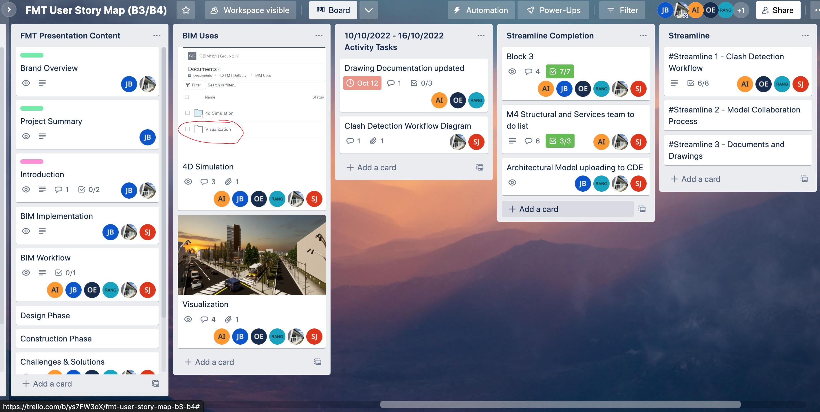
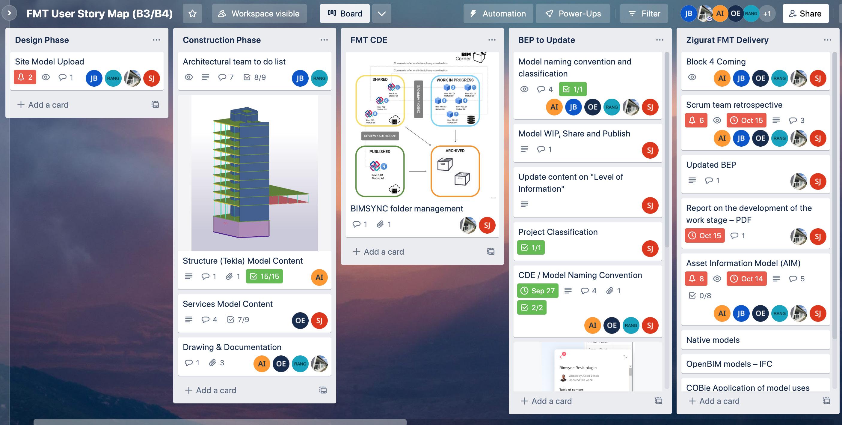
Sprint Planning Overview
Model Progress Summary
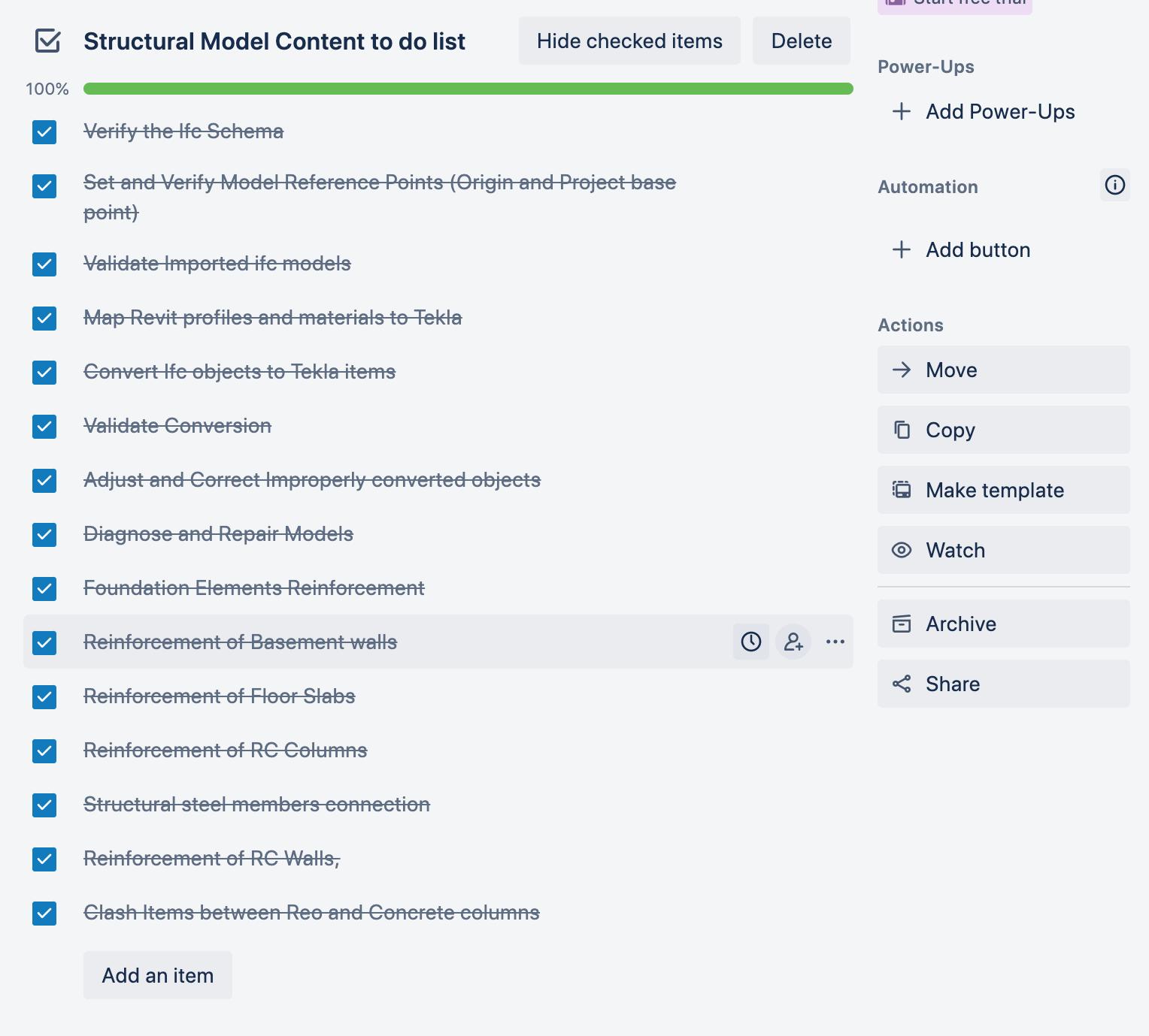
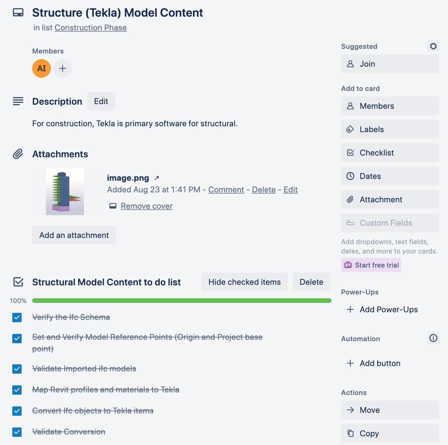
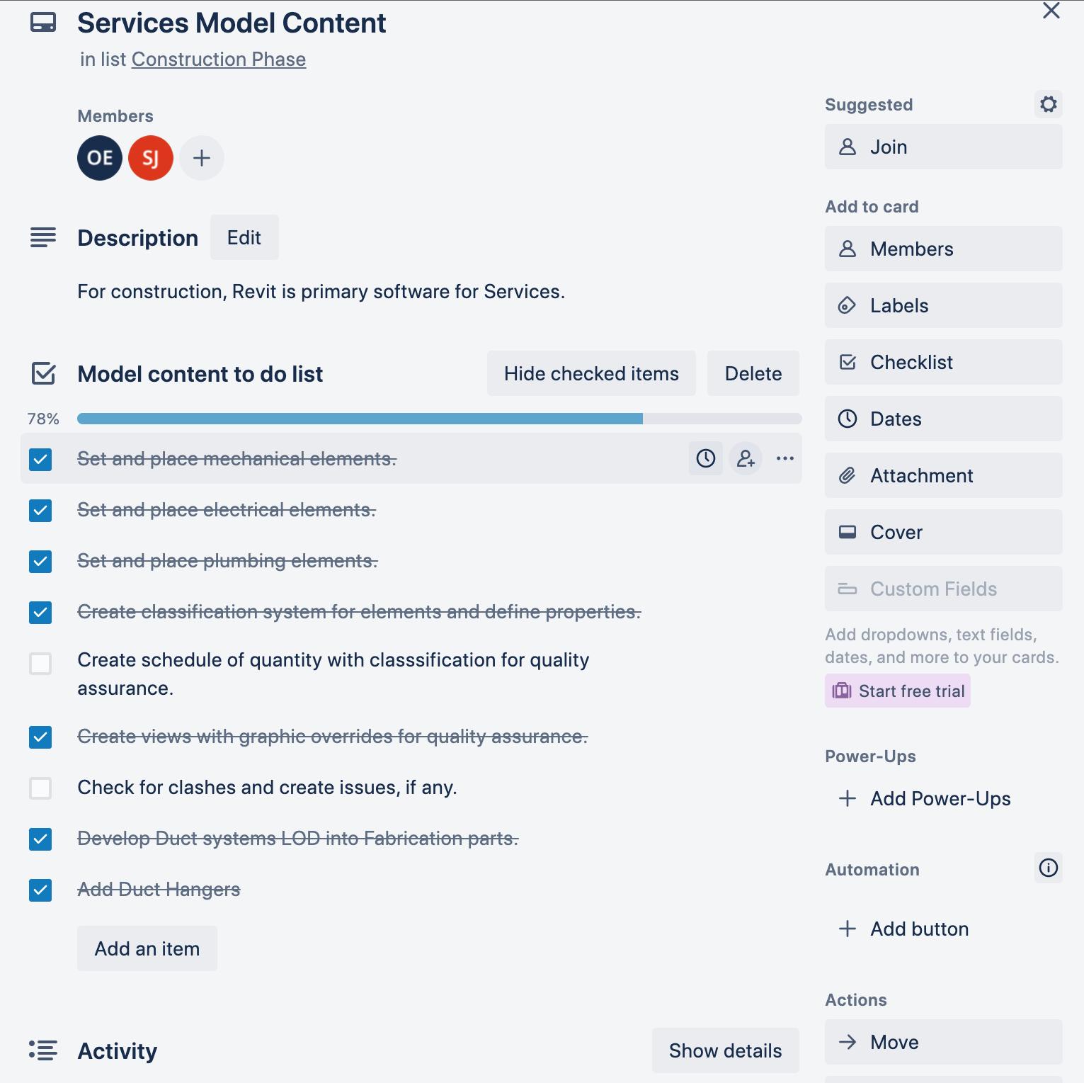
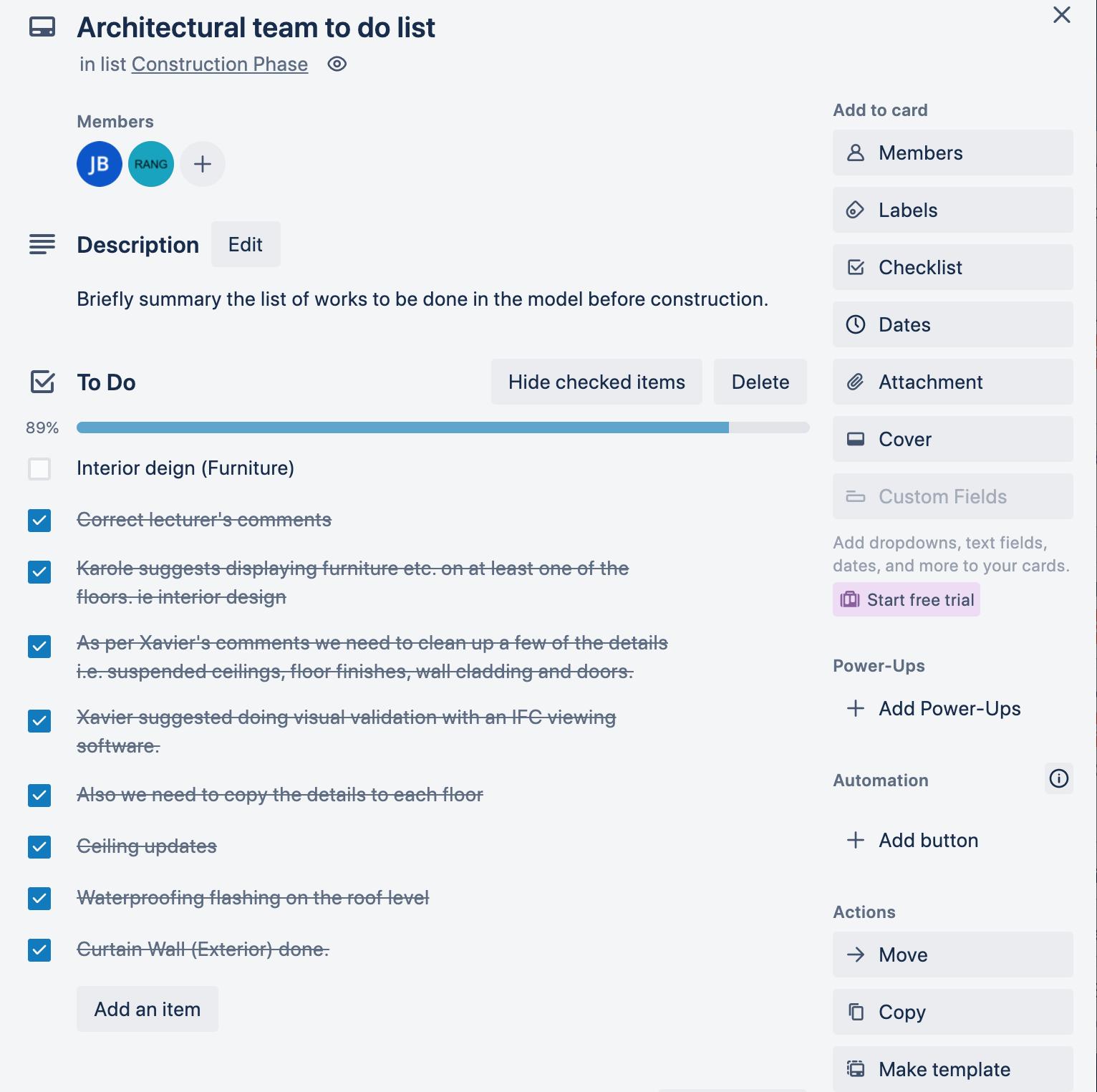
73 Model Progress Summary
SCRUM Retrospective
Scrum Retrospectives were collected on Miro and meeting minutes for Phase 4, for delivery on Octboer 16, 2022.
Member Comments
Group two members In this exercise, we brainstormed our scrum retrospective using Miro’s collaborative board, and then discussed the points in a daily scrum. Our findings can be found illustrated and described below.
Continue
Work in groups.
Working according to individual strengths and weaknesses (SWOT analysis).
Understanding that there will be learning curves.
Scheduled meeting times.
More commitment to our deliverables and assigned responsibilities.
Managing inconvenience of time zones. Stop Stop exchanging models outside of the CDE. Practice collaboration protocols.
Meetings are too long. Planning and prep work necessary.
Reduce meeting time by following agenda.
Invent
Introduction of Miro another collaboration tool for brainstorming and organizing of ideas.
Use Agile and lean management to improve/ refine process.
Determine what is the best way to communicate each idea e.g. film, animation, writing, render etc. Act More commitment to our deliverables and assigned responsibilities.
Utilize BIM sync fully and edit process until we fit into the best work flow.
Commit to putting together FMT reports and additional documents for the thesis.
Understand and follow naming conventions.
Mentor (from Meeting Minutes)
Our main takeaway from mentor meetings was to refine and utilize our collaboration process and CDE environments. Mentor assigned us the task of practicing utilizing CDE for all issue management with a Revit plug-in, as well as using BIM sync to exchange all project files. It forced us to refine our naming conventions and folder organization. For Block 4, we used these suggestions to challenge our collaborative workflow.
SCRUM Retrospective
Continue
Stop
What help us back?
Work in groups.
Working according to individual strengths and weaknesses (SWOT analysis).
Scheduled meeting times + Managing inconvenience of time zones.
More commitment to our deliverables and assigned responsibilities.
Understanding that there will be learning curves. More commitment to our deliverables and assigned responsibilities.
Invent
How can we do things differently?
Miro as collaboration tool for brainstorming and organizing of ideas.
Use Agile and lean management to improve/ refine process.
What help us move forward? 1.
Individually, reflect on what worked and you should continue doing and stop doing, Write down any ideas into the yellow section.
Reflect together
4 min per section 15 min together
Determine best way to communicate each idea eg film, animation, writing, renders
Stop exchanging models outside of the CDE. Practice collaboration protocols.
Meetings are too long. Planning and prep work necessary.
Reduce meeting time by following agenda.
Act
What should we do next?
More commitment to our deliverables and assigned responsibilities.
Utilize BIM sync fully and edit process until we fit into the best work flow.
Commit to putting together FMT reports and additional documents for the thesis.
Understand and follow naming conventions.
Individually, rthink of next steps. Present and commit together.
4 min per section 10 min together
75 SCRUM Retrospective
2.
SCRUM Retrospective
Initial Setup
Phase 1
Pre- tender
Phase 2
Design
Secondary Setup
Phase 3
Pre- construction
Phase 4
Asset/ Opperations Management
Phase 5
Implementation
It is often acknowledged that the clients are the key drivers to steer the construction industry and they are the biggest beneficiary of BIM. Thus, as BIM consultant (Lead Appointed Party) for implementing BIM, an intelligible BIM framework to streamline the clients’ project workflow is devised.
BIM implementation benefits by providing better visualization of the project, designing a customized team workflow, acting as a guide to project participants, eliminating risks and improving collaboration amongst project stakeholders. Early involvement of the stakeholders can improve integration of the process and facilitates the use of BIM.
The various activities undertaken per project representing the main phases of the process: concept, design, construction and operation, and the placement of the main participants: client, designer, contractor, subcontractor and consultants, in the same lanes, involving real-time collaboration and coordination, favours an integrated agile project delivery.
Business process model and notation as structured graphical representation for specifying processes in BIM implementation is detailed, involving, people, process and technology integration.
Implementation
77 Implementation
In this document, BIM_SQUAD introduces our communication workspace on Slack, which is based on Agile principles. This platform is set up in synchrony with Trello, in order to connect with project management workspace. Detailed Slack workspace can be found at : https://shortest.link/2Nwj

Channels
We have created various communication channels which are connected to our project milestones, as well as general boards to organize different types of brainstorming. Decriptions included in chanels. Examples include:
#00-block-1-bim-mgmt
Channel dedicated to management related workflow in Block 1.
#04-fmt-final-block
Channel dedicated to Communication related to FINAL BLOCK workflow.
*FINAL DELIVERY
*ONLINE DEFENSE
Members
Member roles and responsibility describe in detail on Trello boards.
Apps
We have added a few apps that would be helpful in managing workflow, like Zoom for synchronous communication (daily scrum), Google calendar for due dates and meetings, google drive for sharing files, and simple poll for taking votes among the team. We have also synchronized Trello to reference project management boards.
Communication Communication
Agile Management
Kanban, the Japanese word for billboard, is a process developed by Toyota to visually organize ‘to do, doing, and done’ data. This process has since been developed into digital boards such as Trello. Boards allow users to visually organize data, such as, member responsibilities, tasks, task status, task priorities. In order to manage the GBIM1121 FMT Project, BIMSQUAD has organized boards using a SCRUM process, and a communication strategy in accordance with Agile principles. To achieve this we have developed a synchronized process via two digital platforms ‘Slack’ and ‘Trello’.
Scrum Process
Slack allows group members in different time zones to organize communication, by organizing specific channels with different tasks, as well as linking apps such as ZOOM, Google Calendar, Google Drive and Trello. It also provides useful apps such as Simple Poll, which allows for simple and fast decision making.
The Tables below describes the SCRUM process stategy used illustrated on Trello boards.
Stage SCRUM Process Description
1 Assign Roles and Responsibilities
2 Plan Roadmap
3 Block xx User Story Map
4 Create Block xx Sprint Planning Board
In this board, the SCRUM team roles are illustrated with its assigned members. Boards include detailed job descriptions, and task cards that illustrate the various associated responsibilities. As the project progresses, responsibilities must be updated, and time durations should be added to each responsibility to manage work distribution. This is to enable efficient transfer of responsibilities throughout the project.
The road map board is for the vision and targets. A Road Map provides an overview of the entire FMT project and lists the project goals for each block, as well as the expected delivery date.
The user storyboard is for a summary of all required activities at a high level. Visually present activities and tasks to be completed within each block. User Story map will show how many sprints and releases will be used for each user activity column. The header of each User Activity column to show the Date of Completion. Definition of Ready and Definition of Done checklist can be found on this board.
The Sprint Planning Board helps the scrum team to conduct a sprint planning session where the items necessary to complete the user story on the backlog is broken down into smallmore easily manageable chunks. The team selects User Stories from the User Story board and copy to the backlog of the Sprint planning board. In this board detailed requirements for each task are determined under each Sprint, member responsibilities are defined as well as delivery dates.
5 Create Scrum Board We then create a Sprint Scrum board to focus on task delivery and implementation. Scrum master to check the task delivery date to ensure everyone is on board. Labels used to assign member tasks and illustrate levels of priority. Scrum content to cover:
• Work to do
• Work in Progress
• Work to Review/ Check/ Approve
• Work Shared or Published
6 Plan for Daily Scrum, Scrum Review, Scrum Retrospective
SCRUM meetings will be held via Zoom, unless otherwise specified. Additional daily content to be discussed via slack, including meeting minutes and itineraries.
The sprint review is to inspect the outcome of the Sprint and determine future adaptations. The team to refer
Definition of Ready (DoR) and Definition of Done (Dod) at each card.
The Sprint Retrospective aims to improve team efficiency and quality of the work. It will be held at the end of a sprint by ZOOM. So far there is no specific time.
79 Agile Management
Sprint Planning Manual
How to read the Sprint Planning board. (A Reference for discipline teams)
After setting up the user story map. Zooming into particular a Sprint Planning board. The board shall define a list of tasks to be completed for a determined milestone within a given timeline. (usually between 1-2 weeks). It details a sequence of tasks to be delivered, velocity/ time for each task, member roles, and hierarchy of tasks. Described below is the method for reading a Sprint Planning board. Contact Scrum Master for more information.
Stage Description
1 Reference Sprint Planning naming convention to local the Sprint Planning board for the relevant milestone, as well as the Sprint assignment to relevant team/ discipline. BIMSQUAD Sprint Planning naming convention is as follows:(Insert naming convention).
2 Each Sprint will list a sequence of tasks to be completed within a Sprint milestone. Each task will be allocated a velocity or time to be completed. Tasks can be assigned a level of hierarchy or assigned a team member responsible for completing tasks. These labels are color coding for easy visual reference. Please refer to legend for label descriptions.
3 Complex tasks can be broken down further into a checklist of requirements to be completed. These checklists are defined as ‘definition of ready’ and ‘definition of done’.
4 Check and update the status of each task. (Eg. work-in-progress, shared, published, archived.)
5 Address any issues experienced while implementing Sprint in SCRUM Retrospect, and suggest possible areas for improvement. Help create a more efficient environment to work in. Sprints should flow one immediately after the other until final handover.
How to create a Sprint Planning board. (A reference for BIMCoordinator/ Scrum Master.)
Stage Description
1 Define the milestone and timeline for the Sprints Planning. It's important to keep sprints relatively short, from anywhere between 1 to 3 weeks. This allows for quick implementation and feedback.
2 Define each sprint backlog of tasks to be completed for project milestones on the User Story Map board. We decide to split each discipline into different user story columns (US). Under each user story column, the project team should have a meeting to brainstorm the tasks to be completed in the future. BIM Manager and BIM coordinator needs to define the release sequence. Furthermore, it aims to find out the logical sequence and priority order between each release. More complex tasks should contain a checklist of requirements to complete before completion, and should be defined with the ‘definition of ready’ and ‘definition of done.’
3 Create a list of Sprints to be created within the timeline for specified milestones. For example these sprints can be separated into disciplines (MEP/Arch/Struct).
4 Refer to the backlog to create a list of tasks to be completed within each Spring. This should be listed in sequential order. More complex tasks should contain a checklist of requirements to complete before completion, and should be defined with the ‘definition of ready’ and ‘definition of done.’
5 Allocate team members to tasks. Use consistent (color coded) labeling systems for members to visually find their task easily. Create a legend for members to reference.
6 Determine hierarchy and velocity/ time for each task. Label task in order of hierarchy. Hierarchy should be defined in legend.
7 Create logical naming conventions for members to locate the milestone Sprint Planning board and for disciplines to locate their Sprints.
8 At the end of each Sprint, have Sprint Retrospective, to determine improvements for future planning and processes.
9 Create a Sprint Planning board for the next Milestone. Be sure to implement suggestions for SCRUM Retrospective. Sprint Planning Manual
Label Legend
The following legend describes the labels used in the Sprint planning
Label Name Description
User Task Show delivery date, task content, status. Use in the heading on boards.


User Story A task which has been approved by project team on boards
Sprint #xx In the User Story Map Board, vertically grouping tasks into one delivery package

Release #xx: In the User Story Map Board, horizontally grouping tasks into one logic sequence.
Member Label Color code for each discipline role


Poirity Label Legend
The following legend describes the piority labels used in the Sprint planning and colour associated with each label. Label Name Description
Critical most related to time critical. Task to be addressed in one day
High The task is on a critical path. Important and needing to be done or dealt with quickly. Should be addressed 2-3 days.
Normal The task needs to be done but not urgent. The task to be addressed within 1-2 week. Low Least important. Less relevant. The task to be addressed within 2-3 weeks.
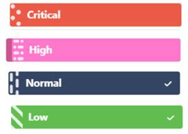
Release 1 81 Sprint Planning Manual
User Story Board showing backlog of tasks for Sprint Planning In this document, BIM_SQUAD introduces its SCRUM strategy used for managing the FMT project, which is based on Agile principles. Details on the Trello boards can be found at https://trello.com/ gbim1121g02/account
BIM Implementation Development: Part 1
Improve firm’s performance and BIM capabilities
Integrated Project Delivery as a procurement method
Establish progressive BIM culture
Explore renewable energy sources
Improved collaboration and valueadded asset management
Lower carbon Footprint
Explore fabrication, industrialization, mass production
Generative processes to develop passive design
Policy
softlanding/ golden thread for ijmproved handover
Time & cost saving
Develop firm to mature adaptation of BIM and use applications
Plan for a sustainable future
Provide affordable solutions
Champion state of the art technology
BIM Goals
Regulatory
Contractual agreements
Benchmarking & Guidelines
Building standards
Research and development
Computer hardware
Computer Network
CDE Platform
Cloud storage/ backup
Technology
Day-to-day communication
Sas Software
Design
Authoring software
Point cloud/ lazer scans
Visualization /AR
Best Practices Review software
BIM Implementation Development: Part 1
BIM IMplementation
Measureable BIM targets
Employee retention Produce highly energy efficient building
Accurate 4D/ 5D simulations/ accurate cost projections Champion standardization and classification
Highly skilled workforce
Sense of fullfillment
Provide doc. for effective operations/ FM
Effective validation and clash detection to avoid errors Task automaition /parametric design
Accurate analytics for energy performance
Increased ROI Effective templates for all repetitive documents
Reduced production cost Generate multiple BIM uses via BIM information containters
Process
Capability analysis
Documentation
CAD systems
New license restrictions
Model Audit Procedure
Library Communication protocol
Pilot project Training Budget proposal and allocation
Performance measuring
Template Coordination workflow
BIM Implementation Development: Part 1
83
BIM Implementation Development: Part 2
Personnel
Documentation
Establish BIM goals and responsibilities
Process
Technology
Access needs and anxiety of the team
Organize and document folder structures
Identify key competitors in league for projects. Establish strategy for being ahead
Research best tools/ software in the industry for BIM uses
Establish valueaddign culture that responds to need and anxietty of employees Establish and document naming conventions for files and folders Evaluate previous projects , and ways to improve Examine associated tools/ software costs
Establish BIM champion that will challenge team to develop BIM maturity Streamline BIM related communication. eg Slack/ Trello/ agile/ kanbam
Identify BIM uses necessary to meet high standards for information delivery
Establish roles and responsibilities necessary for BIM goals Establish systems for managing roles and responsibilities. eg agile management Evaluate project requirements, software and skills needed to meet project milestones
Evaluate whether purchasing tools/ software will yield desired ROI and add value
Ensure staff are equipped to use software efficiently, with training and mentorships
Implementation Development: Part 2
BIM
Evaluate members suitable to fill roles and responsibilities
Determine how to fill gaps: trainig outsourcing or hiring
Establish mentoring environment where skilled train less skilled
Design and automate templates for documents and software that are repetitive
Develop BIM standards and templates/ manuals for selected BIM uses.
Establish project milestones and detail project scopes
Examine current trends in industry( AR, gaming, media). Explore opportunities.
Establish roles and responsibilities and assign appropriate members Develop templates and automations for repetitive tasks
Review Scrum and agile strategies team to ensure member can follow Evaluate performance of software and team members throughout projects
Establish detailed expectations for employees and measureable performance requirements
Establish rewards and consequences for performance evaluations
Measure performances and flow up on rewards and consequences
Set regual scrum retrospectives to evaluate what BIM methods are efective/ ineffefient
Develop BIM processes for design and coordination workflows with maps and details
Schedules maintenance to ensure BIM processes and protocols are being followed
Indentify and resolve existing issues based on assessment reports and audits
85
BIM
Implementation Development: Part 2
Business Process Management
Understanding project value and preliminary costs
Review client brief
Confirm financial target
Understand contract requriements
Discipline involvement
Feasibility study
Financial feasibility study
Environmental feasiblilty study
Design feasiblilty study
Perform GAP analysis
Identify Software solutions
Identify BIM uses Identify hardware capability
Validation and clash detection Design authoring Energy Analysis
Algorithmic/ parametric modeling Visualization
Indentify tools and software required
Develop software applications
Develop templates. Automate repetitive tasks
Company profile/ portfolio
Contract form templates
Prepare proposal
Establish Project scope
Delivery standard
Legal compliance disclaimer
Softlanding protocol
Data security/ privacy
Payment and penalities
Government regulations
Approve proposal
Draft standard
Feedback
NO NO YES START TECHNOLOGY POLICY PROJECT PROCESS BIM STATEMENT PROCESS
START Business Process Management
ROI preparation
Risk Preassesment
Client Approval
Conceptual design Initiate BIM project
Identify Data exchange possiblilties
Open BIM workflow
Collaborative contracts e.g IDP
IFC/ BCF formats
IFC viewers
CDE platforms
Identify Project stakeholders
Information requirements
Classification and standarization
Naming Conventions
Prepare project stakeholder list
Responsibilty matrix
Communication protocols
Spatial coordination
Planned progress inquiry
Planned progress inquiry
Data clouds
e.g Google drive
Detailed design
Identify Network environment
Online clouds
e.g BIM cloud, graphisoft
Construction
FM/OP stage
Saas e.g Microsoft office 360, Adobe CC, Autodesk
Identify Project team’s BIM capability
Identify Target model uses
Learning curve
Project risk vs. capabilites
Historical context
Experience
Workflow and collaboration Task priority list Task information delivery plan
Information management Application standard
Visualization 4D Simulations
Cost estimations
Set BIM collaboration goals
CDE environment
e.g BIM Sync
YES
Quality assurace
Team competency check
Team communication
Model audits
Intellectual property rights
Risks and resposibility
Feedback
Approve standard Publish standard Implement standard
Deploy standard
END
YES
NO
END 87 Business Process Management
Swot Analysis
SWOT analysis (or SWOT matrix) is an acronym for Strengths, Weaknesses, Opportunities, and Threats. It relates to business competition or project planning (Zach,1999). The process is sometimes referred to as situational assessment or situational analysis.
The technique is intended for use at the preliminary stages of decision-making processes and can be used to assess an organization’s strategic position.
The goal is to identify both internal and external factors that are supportive and unsupportive of the project’s goals. SWOT analyses require users to ask and answer questions to generate meaningful information in each category so that they can identify their competitive advantage and make the tool useful for them.
Internal and external factors
Opportunities and threats are typically viewed as external threats, while strengths and weaknesses are usually viewed as internal. Strategic fit refers to how well a firm matches its strengths with its opportunities.
Internal factors are viewed as strengths or weaknesses depending upon their effect on the organization’s objectives. What may represent strengths with respect to one objective may be weaknesses (distractions, competition) for another objective. The factors may include personnel, finance, manufacturing capabilities, and all of the marketing mix’s 4Ps.
External factors include macroeconomics, technological change, legislation, and sociocultural changes, as well as changes in the marketplace.
Strength
What do you do well? What unique resource do you have? What do others compliment or praise?
Automation of template and processes
Reduction of construction cost
Reduction of construction waste due to model validation and clash detection
Multidiscipline experience with certifications in BIM
Shared risk and rewards among all parties. Fair development
Weaknesses?
Improved collaboration/ expert input throughoutt project development.
Where is there room for improvement? What resources do you lack? What critiques do you receive?
High cost of BIM implementation
High labor consumption to create accurate BIM models
No software provides all BIM uses
Need to focus on geometric modelling as well as information management
Quality control and model auditing Design process and coordination time
STRENGTHS WEAKNESSNESS
Swot Analysis
INTERNAL EXTERNAL
Opportunities
What opportunities do you have? What trends can you take advantage of? How can your strengths be uses?
Deleloping higher awareness among all stakeholders
Outsourcing capabilites (e.g Fivrr, LinkedIN)
Threats
What potential treats do you face? What changes in your industry are troublesome? What threats do your weakness expose?
Developments in ditigalization (AR, gaming, blockchain, NFT)
Mandatory implementation of BIM in public procurement in many countries
Pioneering a rapidly evolving industry with high demands for skilled leaders
Strategies to make use of Opportunities through our Strengths
Higher quality of projects should contribute to deleloping higher awareness of all participants
Classifcation advisory to government for facility management
Development of openBIM tools, platforms and applications
Reducing cost of construction projects will increase interest of market leaders in AEC
Utilize media platforms to champion good BIM practices and procure clients
Automation of work should increase research and deveopment
Lack of legal regulations and binding standards concerning BIM
Competition from emerging technology and software
Material cost and scarcity
Lack of qualified and experienced staff Assessibility to information (online content and international standards)
Pandemic
Unwillingness of some contractors/ clients/ users to employ BIM
Strategies to prevent Threats through our Strengths
Tertiary education involvement to influence new technologist and designers
Integreate services with other technology industries (eg blockchain) to provide niche
Strategies to make use of Opportunites to mimimize Weaknesses
BIM implementation in public procurement may create private interests
Examine trends in industry (eg gaming and meadia to develop relatable content)
Government approval for 1/2
Pilot project for strategic development and training
Customize API according to use cases
Use of parametric design tools to improve accuracy of BIM objects and information
Commercial license & license / cloud storage duration control
Education of parties to the process of developing any particular BIM usage
Establish clear EIR/ BEP/ infromation requirements beforehand
Striving to be at the forefront of technological development to attract driven individuals
Develop standards and BIM workflows and procedures
Strategies to miminize potential dangers lying in sectors where Weakness meet Threats
Create training programs and work with educational institutes to supply skill labor
Plan for the unknown such as pandemics (eg remote working infrastructure)
Provide clear marketing content to address BIM implementation fear
Encourage government regulation of BIM implementation and standard of conduct.
Reducing nominal cost of software and training to encourage good practice
Strategic HR management and increased wages to encourage BIM implementation
89 Swot Analysis
CDE Implementation Roadmap
3 MONTHS
Current Projects
Future Projects
Current Issues
Client Initiation Meeting (1-2 times)
One project the client would like the test implementation strategies
Client pilot project meeting
Golden Circle: What is going to happen
When will it happen
Who will be involved and how-
BIM Brief/ goals published
Kickoff meeting
Record next steps
Analyze completeness
Identify incomplete phases
Cost updates and changes
Asses current digtal strategy if any (Organization BIM Maturity Assessment)
Determine what is available
Employee capability assessment
Indentify possible BIM adoption capabilities by conducting surveys and interviews. Indentify KPIs
Asses Infrastructure Validate CDE Implementation Process
IT Strategy
Future Plans Budget
Risk Management
Model hosting
Model publish and Sync procedure
Model link procedure
Shared and published procedure
User permission
Pilot Project Start
Risk Management Final Testing Finalize Standards
Risk Management
Understanding the resistance of new implementation strategies
Expect resistance to future implementation strategies
Training
Consistent training and development (CDE platform updates, model updates):
Scheduled training (CDE start up)
On-demand training (new user)
Specialized training (Project specific)
TOTAL: 2.5 YEARS
CDE Implementation Roadmap
END
START
Software
Hardware
Outsourcing training
Consider ROI in: Organization Stakeholders Technology implementation
Measure of Success
Lessons Learned Pilot project handover
Summary report (Pilot Project)
Pilot project cost update (compare to conventional process
Any expectations from project team
Preferred consultants or main contractor
Restructuring current team
Communication changes and expectations from team
Decision made
Develop standards Prepare organization and IT for transition
Model uploading procedure
Modeling practice guide Coordinaton procedure
Model auditing process
Summary of current software licenses, hardware/ software upgrades
Process/
Model Auditing
Report
capture model changes
BEP
How to
Construction
Design BEP 1 YEAR 1 YEAR
Pilot Project Finish
2 MONTHS Cost Planning
91 CDE
Roadmap
Implementation
BIM Auditing and Performance Metrics
Day to day performance
Quality of the BIM Execution Plan
Quality of the inhouse BIM library and modelling best practise
Elimination of rework
BEP template Identify role and responsibility
Library of standards
Fully Metadata integration between model and asset
Office Culture with BIM process
Delivery on time
Organization Level
On/below budget
IT infrastructure collaborative workflows
File replace ment procedure (Pending, Review, approve)
File organization and naming conventions
CDE workflow protocol
Model updating procedure
MODEL Version upgrade
perpetual learning culture
Model link procedure
Searchable website archive
definition of ready/ definition of done
Model checking
Classification implementation procedure
training material (manuals/ courses etc.)
Model changes
Leveling of understand of BEP (LOD, LOI)
Virtual dashboard to summary the progression map
4D/5D planning
BIM Auditing and Performance Metrics
BIM Dictionary describes Performance Metrics as “Tools and criteria for establishing levels of performance of systems, projects, individuals, teams, organizations and other organizational units (also refer to BIMe Metric)” In order to measure performance throughout the pilot project, we conducted audits as part of this FMT.
In house staff queries (for example, input IFC)
Visual Check Interference
Check standard Check Information
Check
Laser scan integration into Design Software package
test software capabilities
hardware capability
Model and 2D cross referencing check (Can automatically through Dynamo)
Design
Authoring Sotware Automation Check
Predeveloped or developing in house or external plugin
test writing and communication Skill
availability of tools e.g. joystick
Standard guideline for each design stage delivery
Oversize model. How to reduce the model file sizes
Specification crossing referencing to the drawings
Design and construction Knowledge
validation and clash detection
test software capabilities
Model sizes and delivery package establish templates
Individual Level BIM Manual / Documentation Milestone Model review Staff skill Level High quality 3D output from BIM Drawing quality Level of Development Model Performance Check
93
BIM Auditing and Performance Metrics
Execution Process Map
START PROCESS MANAGEMENT QUALITY Preliminary preparation Prepare progress plan Prepare federated site control model Planned progress inquiry Actual progress inquiry Planned schedule Contract requirements Enterprise situation Construction progress plan Progress management interface Read model Audit progress plan FAIL PASS
Execution Process Map
1. Enterprise Situation: Analyse company internal and external situation. BIM implementation scope can be reduced/ increased
2. Construct progress plan
3. Audit progress plan: review and update procurement method and provide clear gap analysis of received design models
4. Progress management interface: Design BEP to be updated and amended to construction BEP. LOD and LOI to be reviewed and updated accordingly
END Actual progress Submission Actual construction progress Updated actual schedule Daily/ weekly report List of scope from site controlled model Record progress Recommended Schema Issue notice of progress Speed up constructionl Required progress RFI Audit actual prgress FAIL PASS
95
Execution Process Map
Acknowledgements
Department Name Details
Faculty Alexandra Caparros
Jaime del Castillo
Director Stefan Mordue
Student assistants for Zigurats Global BIM Management program
Chartered Architect, Construction Project Manager and author, passionate about change within the construction industry. He is Principal Digital Consultant - Europe for AECOM, specializing in Information Management, BIM Delivery and Data Science.
Mentor
Karol Argasiński BIMfaktoria | BIM Manager w BDM’A | Graphisoft Certified BIM Manager & Professional Warsaw, Poland
Lectures
Marzia Bolpagni Building Engineer, PhD | BIM Advisor at Mace London, United Kingdom
Beda Barkokebas Béda Barkokébas is a civil engineer who graduated at the University of Pernambuco (Brazil) and holds a MSc degree at the University of Alberta (Canada). In Brazil, he has experience as a project manager working with project coordination, cost estimation and implementation of BIM systems.
Nando Mogollón Architect, BIM and Digital Engineering Consultant Director at BuilDigital
Xavier Coll Amargant I+D in E&W, Lecturer of Rehabilitation in BIM at Gremi de Constructors de Barcelona, Project Manager I+D, Nemetschek Consultant at EiPM, Catalonia
Jose Carlos Coya Architect, Structural consultant and lecturer. Revit specialist. Cangas Do Morrazo, Galicia, Spain
Sergi Ferrater Gabarró Architect and Product Manager of BIM/VDC 3D-4D Software | Bentley Institute Product Training Partner Barcelona, Catalonia
Mirbek Bekboliev
M.Sc. Building Science / Technical Project Manager @buildingSMART Germany / Sustainability Consultant LEED GA Passivhaus, Germany
Mahmoud El Charif Head of Digital Construction at Urban Surveys. Bachelor of Architecture
Global BIM Management Master building SMART UAEMCIBSE
Karel Kalis
Academic Director Global master’s in construction project management
Head of value at Janssen de Jong Group
Acknowledgements
Our personal thanks
It is very important for BIM Squad to acknowledge the professionalism of the faculty who helped deliver an outstanding experience and outcome for the global BIM masters program. Firstly, we wish to thank the facilitators, who addressed any concerns/issues we had throughout the course and kept us updated on all developments. In addition to providing a well-prepared global BIM master’s course, faculty maintained communication and coordinated among themselves throughout the course. Intermittent meetings were held with students, during which issues were discussed with our director. As part of the Agile process, Stephan Mordue provided support resources and lecturers to facilitate subjects in need of additional support. BIM Squad members appreciate all the professionalism and care you put into managing this program. As a team, we are extremely proud of our accomplishments.
Mentorship is one of the unique advantages of Zigurat’s global BIM masters program. Mentorship is required in all alternative accreditation processes. Mentorship was prioritized in GBIM, in which mentors directly served participants’ development and success. In the process, participants developed pilots, templates, manuals, workflows and processes to enhance their professional careers. Karol was exceptionally generous with his time and knowledge. The professor demonstrates a thorough understanding of openBIM practices, which he challenged us to master aggressively. Our sincere gratitude goes out to you for your efficiency and kindness.
Zigurat provided a great selection of lecturers who were experienced, accredited, and recognized by Autodesk, Graphisoft, Bre Academy, and CanBIM. This was reflected in the quality of content delivered within expedited timelines. Our BIM Squad members are very passionate about BIM, and we would like to thank our lecturers for their obvious passion for BIM and human development. It is a pleasure to commend all of you for your excellent work.
97 Acknowledgements
Acknowledgements
Luis Pinto Martinho BIM Consultant
Post graduated in BIM for Integrated Project Delivery
Universidade Lusófona, Lisboa
Master BIM Manager Zigurat Global Institute of Technology
COBie Specialist Universidade da Flórida
Associate Member CanBIM (Canada BIM Council)
COBie Associate Prairie Sky Consulting LLC
Pat Slattery Founder and Managing Director at Arcdox.
Rui de Klerk
MSc degree in Architecture from the Faculty of Architecture, University of Lisbon
Product Developer at GeoFluxus.
Louis Oghenemaro Sota Academic Qualifications: BSc. Civil Engineering, MSc.
Engineering Project Management, Rail Engineering Diploma
Professional Qualifications: PMP, Prince2 and AgilePM
Practitioner, IOSH Managing Safely, BREEAM AG, NEBOSH
Construction, CMI L7 Professional Consulting
William Rezende Mechanical Engineer & Senior
Tekla Detailer at AMO Steel
Detailing Ltd
Mahya Nazari
Master’s in architecture IAU
Master’s in building information Modelling
BIM Advisor
BIM Specialist, INEA company
Bim Specialist, Gedcom institute
99 Acknowledgements