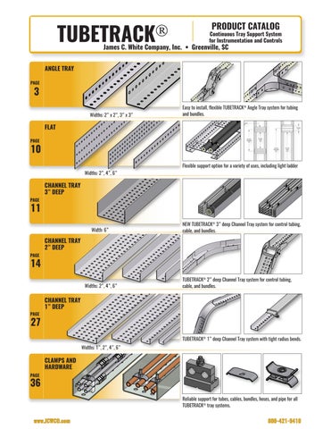
TUBETRACK® Catalog

Page 1


TUBETRACK®

PRODUCT CATALOG

Continuous Tray Support System for Instrumentation and Controls

James C. White Company, Inc. • Greenville, SC

Easy to install, flexible TUBETRACK® Angle Tray system for tubing and bundles.

► About James C. White Company, Inc.

We began as a partnership in 1952 as a distributor of tube fittings and valves. Two years later Jim and Bettye White took the Company to a new level and began manufacturing TUBETRACK®, Jim White’s design of the first use of a Tray Support System for instrumentation tubing. The TUBETRACK® Tray System was the first industrial category of Instrument Support Tray.

To this day we have maintained the culture of quality and attention to detail that Jim and Bettye White so deeply ingrained in our personnel. Jim White was well known for many “famous” mottoes he used to guide the company and which he passed on to the current generation of company leadership. One of those mottoes that still directs the company today is:

“Good business is business that is good for both parties.”

Under the direction of Tom White, owner and president, we have made significant advances in new product design and manufacturing improvements since 2005. James C. White Co. is a growing, innovative manufacturing company with complete fabrication and machining capabilities. Although a small business, we have served some of the world’s largest EPC firms and supplied materials on time to some of the largest industrial projects in the world.

We welcome opportunities to partner with you to solve your special instrumentation support needs. Over the years we have custom machined or fabricated numerous custom products which are not catalog-standard items. If you don’t find what you need in our catalogs, please contact the factory. There is a good possibility we may already have a solution or can partner with you to provide one.

Thank you for your continued interest in the James C. White Company.

► Quality Assurance Program

• Maintained and advanced for over 40 years

• Designed to conform to applicable requirements of: 10CFR50 Appendix B, ASME NQA-1a-2009, ASME Boiler and Pressure Vessel Code Section III, Subarticle NCA-3800, MIL-Q9858A, and MIL-I-45208A

• Controls our manufacturing, inspection, and shipping activities as applicable to your order requirements

• Meets or exceeds various other Q.A. Program requirements, such as ISO

• Routinely audited by various customers and utilities, including NUPIC members

Throughout our TUBETRACK® and CABLE-RACE® catalogs, Hot-Dip Galvanized and Stainless Steel materials marked with a symbol can be supplied as Safety-Related for use in nuclear facilities, in accordance with 10CFR50 Appendix B, ASME NQA-1, ASME B&PV Code, Section III NCA-3800 and/or CSA N299.2.

Contact our Nuclear Sales Department regarding availability, load rating, material and part specifications, or to inquire about the possibility of procuring other materials as Safety-Related.

TUBETRACK

2”

and 3” Angle Tray

Straight Angle Tray

TUBETRACK® standard angle tray sections are available in 4 corrosion-resistant metals. TUBETRACK® components are factory inspected for quality of fabrication detail, finish, straightness, and appearance.

Angle tray details are shown for standard size, part numbers, materials, widths, lengths, and gages. Other non-standard gages are available for 304SS and 316SS angle tray but are generally not available from factory stock. See page 50 for Load and Deflection information.

NOTE: TUBETRACK® Angle Tray is not UL Classified.

Non-Standard Gages:

* 3” deep Angle Tray is a new product - may not be immediately available from stock. Contact factory.

Structural connections for 2” and 3” TUBETRACK® angle tray splices and bends are provided with 3/8” dia. bolt sets (truss head bolts with flanged locking nuts). Truss head bolts with hex nuts and flat washers are optional upon request. Bolt sets are supplied with all TUBETRACK® splices and bends.

Standard fastener metals include:

• Zinc-plated bolts with galvanzied fittings

• 18-8 stainless bolts with aluminum fittings

• 18-8 stainless bolts with 304 SS fittings

• 316 stainless bolts with 316 SS fittings

Bolted Connections

TUBETRACK® uses only tightenable fasteners to secure tray connections. Splices bolt through the first and third round holes in each end of a splice, in both angle legs for maximum strength. Bolt sets are supplied with each TUBETRACK® splice and bend. Stainless steel bolting is standard with stainless steel and aluminum TUBETRACK® fittings. Stainless steel bolting is optional with galvanized TUBETRACK® for an additional cost. Contact factory for additional information.

TUBETRACK®

Angle Splice

Straight Connections

Includes 3/8” dia. bolting Metal

Expansion Angle Splice

Includes 3/8” dia. bolting

Hot-Dip Galvanized Steel 2 3*

Natural Finish Aluminum 2 3

Stainless Steel T-304 2 3*

Stainless Steel T-316 2 3*

A: 11.5”

Nominal Engagement: 5.5”

SA2-GC2

SA3-GC3

SA2-NA2

SA3-NA3

SA2-SS2T4

SA3-SS3T4

SA2-SS2T6

SA3-SS3T6

* 3” deep Angle Tray is a new product - may not be available from stock. Contact factory.

Hot-Dip Galvanized Steel 2 3*

Natural Finish Aluminum 2 3*

Stainless Steel T-304 2 3*

SA2-GC2-X

SA3-GC3-X

SA2-NA2-X

SA3-NA3-X

SA2-SS2T4-X

SA3-SS3T4-X

Stainless Steel T-316 2 3* SA2-SS2T6-X SA3-SS3T6-X

A: 14.4”

Nominal Engagement: 5.5”

* 3” deep Angle Tray is a new product - may not be available from stock. Contact factory.

Expansion Splice Angle

Allows for longitudinal expansion of up to 2” total movement. Use for thermal expansion, vibration, and at building or frame expansion joints.

Includes 3/8” dia. bolt sets (truss head bolts with flanged locking nuts).

Elbow Inside Angle - 90° Flat Plate

0-3” Radius

Includes 3/8” dia. bolting

Elbow Inside Angle - 90° With Flange

0-3” Radius

Includes 3/8” dia. bolting

Elbow Inside Angle - 45° Flat Plate

0-3” Radius

Includes 3/8” dia. bolting

Elbow Inside Angle - 45° With Flange

0-3” Radius

Includes 3/8” dia. bolting

3” Radius Fittings

Metal Part No.

Hot-Dip Galvanized Steel

Natural Finish Aluminum

EIA2-GC-R3D90

EIA2-NA-R3D90

Stainless Steel T-304 EIA2-SS-R3D90T4

Stainless Steel T-316 EIA2-SS-R3D90T6

A: 5.5” Nominal Engagement: 3.5”

Metal Part No.

Hot-Dip Galvanized Steel EIAH2-GC2-R3D90

Natural Finish Aluminum EIAH2-NA2-R3D90

Stainless Steel T-304 EIAH2 SS2 R3D90T4

Stainless Steel T-316 EIAH2 SS2 R3D90T6

A: 6.0” Nominal Engagement: 3.5”

Metal Part No.

Hot-Dip Galvanized Steel EIA2-GC-R3D45

Natural Finish Aluminum EIA2-NA-R3D45

Stainless Steel T-304 EIA2-SS-R3D45T4

Stainless Steel T-316 EIA2-SS-R3D45T6

A: 5.25” B: 9.0” Nominal Engagement: 4.5”

Metal Part No.

Hot-Dip Galvanized Steel

EIAH2-GC2-R3D45

Natural Finish Aluminum EIAH2-NA2-R3D45

Stainless Steel T-304 EIAH2 SS2 R3D45T4

Stainless Steel T-316 EIAH2 SS2 R3D45T6

A: 5.25” B: 9.25” Nominal Engagement: 4.5”

TUBETRACK®

Elbow Outside Angle - 90° 3” Radius

Includes 3/8” dia. bolting

Elbow Outside Angle - 45° 3” Radius

Includes 3/8” dia. bolting

Tee Angle 3” Radius

Cross Angle 3” Radius A Metal

Includes 3/8” dia. bolting

Includes 3/8” dia. bolting

Hot-Dip Galvanized Steel

EOA2-GC2-R3D90

Natural Finish Aluminum EOA2-NA2-R3D90

Stainless Steel T-304 EOA2-SS2 R3D90T4

Stainless Steel T-316 EOA2-SS2 R3D90T6

A: 9.25” Nominal Engagement: 3.5”

Hot-Dip Galvanized Steel EOA2-GC2-R3D45

Natural Finish Aluminum EOA2-NA2-R3D45

Stainless Steel T-304 EOA2-SS2 R3D45T4

A: 6.25” B: 10.75” Nominal Engagement: 3.5”

Stainless Steel T-316 EOA2-SS2 R3D45T6 Metal

Hot-Dip Galvanized Steel

TA2-GC2-R3D90

Natural Finish Aluminum TA2-NA2-R3D90

Stainless Steel T-304 TA2-SS2-R3D90T4

A: 16.75” B: 10” Nominal Engagement: 3.5”

Stainless Steel T-316 TA2-SS2-R3D90T6 Metal Part No.

Hot-Dip Galvanized Steel

KA2-GC2-R3D90

Natural Finish Aluminum KA2-NA2-R3D90

Stainless Steel T-304 KA2-SS2-R3D90T4

Stainless Steel T-316 KA2-SS2-R3D90T6

A: 16.75” Nominal Engagement: 3.5”

Inside Channel Vertical

Adjustable Bend (0-90°) Patent No.: US 8,167,250 B2

Adjustable Fittings

A: 6.0”

Nominal Engagement: 3.5”

Includes 3/8” dia. bolting (same part shown on page 20). Cut angles so that round holes are on the connecting end.

Outside Channel Vertical

Adjustable Bend (0-90°)

B2

T-316 OCV2-SS2-DAT6

A: 5.25” Nominal Engagement: 3.5”

Includes 3/8” dia. bolting (same part shown on page 21). Cut angles so that round holes are on the connecting end.

Offset Channel Vertical

Double Adjustable Bend Patent No.: US 8,167,250 B2

Hot-Dip Galvanized Steel

OCV2-GC2-DDA5

Natural Finish Aluminum OCV2-NA2-DDA5

Stainless Steel T-304 OCV2-SS2-DDA5T4

Stainless Steel T-316 OCV2-SS2-DDA5T6

A: 6.0”

X: Offset at 45° (pictured): 3.25”

Max offset (bends at 90°): 5”

Nominal Engagement: 3.5”

Includes 3/8” dia. bolting (same part shown on page 22). Cut angles so that round holes are on the connecting end.

Horizontal Elbow

Adjustable Bend (0-90°) Patent

B2

Hot-Dip Galvanized Steel

Natural Finish Aluminum

Stainless Steel T-304

EC2-GC2-R6DA

EC2-NA2-R6DA

EC2-SS2-R6DAT4

Includes 3/8” dia. bolts and locking nuts

Stainless Steel T-316

6” Min. Radius A = 13” B = 7” (nominal dim.)

EC2-SS2-R6DAT6

Elbow Inside Angle - 90° 14” Radius

Includes 3/8” dia. bolting

Elbow Inside Angle - 45° 14” Radius

Includes 3/8” dia. bolting

Elbow Outside Angle - 90° 12” Radius

Includes 3/8” dia. bolting

Elbow Outside Angle - 45° 12” Radius

Includes 3/8” dia. bolting

12”+ Radius Fittings

Hot-Dip Galvanized Steel EIA2-GC2-R14D90 Natural Finish Aluminum EIA2-NA2-R14D90 Stainless Steel T-304 EIA2 SS2 R14D90T4

Steel T-316 EIA2 SS2 R14D90T6

A: 19.75” Nominal Engagement: 3.5”

No. Hot-Dip Galvanized Steel EIA2-GC2-R14D45

Natural Finish Aluminum EIA2-NA2-R14D45 Stainless Steel T-304 EIA2 SS2 R14D45T4

Steel T-316 EIA2 SS2 R14D45T6

A: 21.5” B: 10.5” Nominal Engagement: 3.5”

Hot-Dip Galvanized Steel EOA2-GC2-R12D90

Natural Finish Aluminum EOA2-NA2-R12D90

Stainless Steel T-304 EOA2 SS2 R12D90T4 Stainless Steel T-316 EOA2 SS2 R12D90T6

A: 22.0” Nominal Engagement: 3.5”

Hot-Dip Galvanized Steel EOA2-GC2-R12D45

Natural Finish Aluminum EOA2-NA2-R12D45

Stainless Steel T-304 EOA2 SS2 R12D45T4 Stainless Steel T-316 EOA2 SS2 R12D45T6

A: 21.5” B: 10.5” Nominal Engagement: 3.5”

Includes 3/8” dia. bolting

12”+ Radius Fittings

Natural Finish Aluminum TA2-NA2-R12D90

Stainless Steel T-304 TA2-SS2 R12D90T4

Stainless Steel T-316 TA2-SS2 R12D90T6

A: 37.75” B: 20.25”

Nominal Engagement: 3.5”

Includes 3/8” dia. bolting A

Hot-Dip Galvanized Steel KA2-GC2-R12D90 Natural Finish Aluminum KA2-NA2-R12D90

Stainless Steel T-304 KA2-SS2 R12D90T4

Stainless Steel T-316 KA2-SS2 R12D90T6

A: 37.75”

Nominal Engagement: 3.5”

TUBETRACK®

TUBETRACK® standard flat sections are available in 4 corrosionresistant metals and 3 widths. TUBETRACK® components are factory inspected for quality of fabrication detail, finish, straightness, and appearance. Flat details are shown for standard size, part numbers, materials, widths, lengths, and gages.

NOTE: TUBETRACK® Flats and Angles are not UL classified.

Use TUBETRACK® 2” or 3” Angle and Flat to field-fabricate light ladder tray. Purchase fasteners separately. See page 3 for TUBETRACK® Angle and page 44 for 3/8” Truss-Head Bolts & Nuts to complete the assembly.

3” Deep Channel Tray

Straight Channel Tray

Channels - 3” Deep

NEW FROM JCWCO:

3” Deep TUBETRACK® standard tray channel sections are available in 4 corrosion-resistant metals and 6” channel width. TUBETRACK® components are factory inspected for quality of fabrication detail, finish, straightness, and appearance.

Channel tray details are shown for standard TUBETRACK® part numbers, materials, widths, lengths, gages, and covers.

See page 50 for Load and Deflection information.

Channel Splice

3” deep Channel Tray is a new product - may not be available from stock. Contact factory.

A: 11.50”

Nominal Engagement: 5.5” Includes 3/8” dia. bolting

3” deep Channel Tray is a new product - may not be available from stock. Contact factory.

TUBETRACK®

Transition Splice Right Hand

Transition Splice Left Hand

Straight Connections

Hot-Dip Galv. Steel* 6 SCT6-GC2-RH -

Natural Finish Alum. 6 SCT6-NA2-RH -

Stainless Steel T-304 6 SCT6-SS2T4-RH -

A: 10.50” Nominal Engagement: 3.5”

Transition Splices are marked with “L” or “R” to indicate Left or Right

Includes 3/8” dia. bolting

Channel & Fitting Cover Clamps

Stainless Steel T-316 6 SCT6-SS2T6-RHMetal

Hot-Dip Galv. Steel* 6 SCT6-GC2-LH

Natural Finish Alum. 6 SCT6-NA2-LHStainless Steel T-304 6 SCT6-SS2T4-LH -

Stainless Steel T-316 6 SCT6-SS2T6-LH -

A: 10.50” Nominal Engagement: 3.5”

Transition Splices are marked with “L” or “R” to indicate Left or Right

• Clamp: CCC6-SS6-3

• Channel: 6” x 3”

Four piece set includes base, U-bolt, and two hex flange nuts, all in 300 series stainless steel. Straight length covers (10 ft. and 12 ft. long) usually require three Channel Cover Clamps (“CCC”), and fitting covers usually require one Fitting Cover Clamp (“FCC”) per end. Bases are marked with “C” or “F” to indicate Channel or Fitting.

Also available in 304 Stainless Steel - contact Factory. Sold Separately from Cover

TUBETRACK

Horizontal Drop-Out Fitting

Straight Connections

Nominal Engagement: 3.5”

See pg. 31 for Horizontal Drop-Out Fitting for 1” deep tray

* Same width as standard 2” wide TUBETRACK® tray. Use with any CABLE-RACE® or TUBETRACK® fitting.

Attachable Horizontal Drop-Out Fitting

• Drop-Out to an instrumentation station or work station

• Bolt directly to any 3” deep TUBETRACK® tray

• No need to cut or modify existing mainline tray

• Drop-Out at any point along the TUBETRACK® main line tray

• Extend using any 2” wide CABLE-RACE® or TUBETRACK® tray fitting

• Use single Drop-Out fitting with a TUBETRACK® fitting for desired configuration

• All TUBETRACK® fittings include required fasteners

• Includes mounting bracket and fasteners for connection to 3” deep tray

• Available in stainless steel - fits TUBETRACK® tray of any metal

Examples of possible configurations using this single fitting for each Drop-Out:

1” / 2” Deep Horizontal DropOut Fitting

2” Deep Channel Tray

Straight Channel Tray

Channels - 2” Deep

TUBETRACK® standard tray channel sections are available in 4 corrosion-resistant metals and 3 channel widths. TUBETRACK® components are factory inspected for quality of fabrication detail, finish, straightness, and appearance.

Channel tray details are shown for standard TUBETRACK® part numbers, materials, widths, lengths, gages, and covers. Other non-standard gages are available for 304SS and 316SS channels but are generally not available from factory stock.

See page 49 for Load and Deflection information.

Non-Standard Gages:

Structural connections for 2” deep TUBETRACK® tray splices and bends are provided with 3/8” dia. bolt sets (truss head bolts with flanged locking nuts). Truss head bolts with hex nuts and flat washers are optional upon request. Bolt sets are supplied with all TUBETRACK® splices and bends.

Standard fastener metals include:

• Zinc-plated bolts with galvanized fittings

• 18-8 stainless bolts with aluminum fittings

• 18-8 stainless bolts with 304 SS fittings

• 316 stainless bolts with 316 SS fittings

Bolted Connections

TUBETRACK® uses only tightenable fasteners to secure tray connections and maintain the conductivity necessary for UL classification. Splices bolt through the first and third round holes in each end of a splice for maximum strength. Bolt sets are supplied with each TUBETRACK® splice and bend. Stainless steel bolting is standard with stainless steel and aluminum TUBETRACK® fittings. Stainless steel bolting is optional with galvanized TUBETRACK® for an additional cost. Contact factory for additional information.

6” Inside Width
Inside Width
Inside Width

Includes 3/8” dia. bolting

Transition Splice Right Hand

Includes 3/8” dia. bolting

Transition Splice Left Hand

Includes 3/8” dia. bolting

Straight Connections

A: 11.50” Nominal Engagement: 5.5”

Transition Splices are marked with “L” or “R” to indicate Left or Right

Transition Splices are marked with “L” or “R” to indicate Left or Right

Make splice connections for channels through the first and third round holes in each end of the splice for maximum strength.

Straight Connections

Nominal Engagement

The nominal engagement is the overlap of tray inside the splice or bend fitting. TUBETRACK® channel fits inside each end of this splice for a nominal engagement of 5.5”. Use fitting dimensions to estimate straight channel lengths for a job.

Covers

Covers for each fitting are installed over the fitting and over the cover of the channel connected to the fitting to cover the entire connection.

Channel Cover Clamps and Fitting Cover Clamps allow for easy re-opening and re-closing after cabling changes. Clamp bases are marked with “C” or “F” to indicate Channel or Fitting.

Use TUBETRACK® Fitting Cover Clamps to hold down each end of a bend fitting cover. Channel Cover Clamps hold covers along straight tray.

Choice of Radius

3” and 12” radius bends (3 widths, 4 metals) are standard with dimensions and part numbers shown in this catalog. Other bend radii are available. Non-stock standards are available now for many fittings in 6”, 18”, 24”, and 36” radius.

Also available are specific radius requirements. Special radii can mean 29-inch radius or 29-foot radius to match storage tank circumferences or other large curves. Contact factory for additional information.

Includes 3/8” dia. bolting

Includes 3/8” dia. bolting

Elbow Channel 45° Bend 3” Min. Radius

3/8” dia. bolting

Channel 45° Bend 6” Min. Radius

Includes 3/8” dia. bolting

Fittings

A: 7.25” plus channel width

Nominal Engagement: 3.5”

CV-E2 MG2 R6D90

NA2 R6D90

CV-E4 NA2 R6D90

CV-E6 NA2 R6D90

CV-E2 SS2 R6D904

CV-E4 SS2 R6D904

CV-E6 SS2 R6D904

CV-E2 SS2 R6D906

CV-E4 SS2 R6D906

EC6-SS2-R6D90T6 CV-E6 SS2 R6D906

A: 12.0” plus channel width Nominal Engagement: 3.5”

MG2 R3D45

CV-E2 NA2 R3D45

CV-E4 NA2 R3D45

CV-E6 NA2 R3D45

CV-E2 SS2 R3D454

EC4-SS2-R3D45T4 CV-E4 SS2 R3D454

CV-E6 SS2 R3D454

CV-E2 SS2 R3D456

CV-E6 SS2 R3D456

A: 9.31” B: 4” plus channel width Nominal Engagement: 3.5”

CV-E4 MG2 R6D45

CV-E6 MG2 R6D45

CV-E2 NA2 R6D45

EC4-NA2-R6D45 CV-E4 NA2 R6D45

EC6-NA2-R6D45 CV-E6 NA2 R6D45

EC2-SS2-R6D45T4 CV-E2 SS2 R6D454

EC4-SS2-R6D45T4 CV-E4 SS2 R6D454

EC6-SS2-R6D45T4 CV-E6 SS2 R6D454

EC2-SS2-R6D45T6 CV-E2 SS2 R6D456

EC4-SS2-R6D45T6 CV-E4 SS2 R6D456

EC6-SS2-R6D45T6 CV-E6 SS2 R6D456

A: 13.75” B: 6.0” plus channel width

Nominal Engagement: 3.5”

Channel

Includes 3/8” dia. bolting

3-6” Radius Fittings

A: 14.25” plus channel width B: 7.25” plus channel width Nominal Engagement: 3.5”

Includes 3/8” dia. bolting

Cross Channel 90° Bend 3” Min. Radius

Includes 3/8” dia. bolting

Includes 3/8” dia. bolting

CV-T4 SS2 R6D906

TC6-SS2-R6D90T6 CV-T6 SS2 R6D906 A: 23.75” plus channel width B: 12.25” plus channel width

Nominal Engagement: 3.5”

MG2 R3D90

R3D90

CV-K2 NA2 R3D90

CV-K4 NA2 R3D90

CV-K6 NA2 R3D90

CV-K2 SS2 R3D90T4

KC4-SS2-R3D90T4 CV-K4 SS2 R3D90T4

KC6-SS2-R3D90T4 CV-K6 SS2 R3D90T4

CV-K2 SS2 R3D90T6

CV-K4 SS2 R3D90T6

CV-K6 SS2 R3D90T6

A: 14.5” plus channel width Nominal Engagement: 3.5”

CV-K4 MG2 R6D90

CV-K6 MG2 R6D90

CV-K2 NA2 R6D90

CV-K4 NA2 R6D90

CV-K6 NA2 R6D90

CV-K2 SS2 R6D904

CV-K4 SS2 R6D904

CV-K6 SS2 R6D904

CV-K2 SS2 R6D906

CV-K4 SS2 R6D906

CV-K6 SS2 R6D906

A: 23.75” plus channel width

Nominal Engagement: 3.5”

Horizontal Elbow Adjustable Bend (0-90°)

Patent No.: US 8,573,409 B2

6” Min. Radius

Includes 3/8” dia. bolts and locking nuts

Includes 3/8” dia. bolting

Includes 3/8” dia. bolting

Includes 3/8” dia. bolting

EC6-NA2-R6DA

EC4-SS2-R6DAT6

EC6-SS2-R6DAT6

2” Width Tray: A = 13”, B = 7” (nominal dim.)

4” Width Tray: A = 16”, B = 8” (nominal dim.)

6” Width Tray: A = 16”, B = 10” (nominal dim.)

Nominal Engagement: 3.5”

CV-I6 MG2 R3D90

CV-I2 NA2 R3D90

CV-I4 NA2 R3D90

CV-I6 NA2 R3D90

CV-I2 SS2 R3D90T6

SICV4-SS2-D90T6 CV-I4 SS2 R3D90T6

SICV6-SS2-D90T6 CV-I6 SS2 R3D90T6

A: 7.25” Nominal Engagement: 3.5”

CV-I4 MG2 R3D90

CV-I6 MG2 R3D90

ICV2-NA2-R3D90 CV-I2 NA2 R3D90

ICV4-NA2-R3D90 CV-I4 NA2 R3D90

ICV6-NA2-R3D90 CV-I6 NA2 R3D90

ICV2-SS2 R3D90T4 CV-I2 SS2 R3D90T4

ICV4-SS2 R3D90T4 CV-I4 SS2 R3D90T4

ICV6-SS2 R3D90T4 CV-I6 SS2 R3D90T4

ICV2-SS2 R3D90T6 CV-I2 SS2 R3D90T6

ICV4-SS2 R3D90T6 CV-I4 SS2 R3D90T6

ICV6-SS2 R3D90T6 CV-I6 SS2 R3D90T6

A: 7.25” B: 8.0” Nominal Engagement: 3.5”

R6D90T4 CV-I2 SS2 R6D904

R6D90T4 CV-I4 SS2 R6D904

R6D90T4 CV-I6 SS2 R6D904

R6D90T6 CV-I2 SS2 R6D906

R6D90T6 CV-I4 SS2 R6D906

R6D90T6 CV-I6 SS2 R6D906 A: 10.75”

Nominal Engagement: 3.5”

Includes 3/8” dia. bolting

Includes 3/8” dia. bolting

Includes 3/8” dia. bolting

Outside Channel Vertical

CV-I6 NA2 R6D45

R6D45T4 CV-I2 SS2 R6D454

R6D45T4 CV-I4 SS2 R6D454

ICV6-SS2 R6D45T4 CV-I6 SS2 R6D454

R6D45T6 CV-I2 SS2 R6D456

ICV4-SS2 R6D45T6 CV-I6 SS2 R6D456

ICV6-SS2 R6D45T6 CV-I4 SS2 R6D456

15.75” B: 8.0” Nominal Engagement: 3.5”

6.0” Nominal Engagement: 3.5”

CV-O4 MG2 R3D90

CV-O6 MG2 R3D90

R3D90T4

Includes 3/8” dia. bolting

Includes 3/8” dia. bolting

Outside Channel Vertical 45° Bend 6” Min. Radius

B Includes 3/8” dia. bolting

CV-O6 NA2 R6D90

OCV2-SS2 R6D90T4 CV-O2 SS2 R6D904

A: 10.00” Nominal Engagement: 3.5”

CV-O2 NA2 R3D45

CV-O4 NA2 R3D45

OCV6-NA2-R3D45 CV-O6 NA2 R3D45

R3D45T4 CV-O2 SS2 R3D45T4

R3D45T4 CV-O4 SS2 R3D45T4

A: 10.9” B: 4.5” for 2” width A: 9” B: 3.75” for 4” and 6” widths Nominal Engagement: 3.5”

A: 15.25” B: 6.25”

Nominal Engagement: 3.5”

CV-O6 NA2 R6D45

R6D45T4 CV-O2 SS2 R6D454

R6D45T4 CV-O4 SS2 R6D454

R6D45T4 CV-O6 SS2 R6D454

R6D45T6 CV-O2 SS2 R6D456

R6D45T6 CV-O4 SS2 R6D456

R6D45T6 CV-O6 SS2 R6D456

Offset Channel Vertical Double Adjustable Bend Patent No.: US

Includes 3/8” dia. bolting X

A: 6.0”

X: Offset at 45° (pictured): 3.25” Max offset (bends at 90°): 5”

Nominal Engagement: 3.5”

Horizontal Drop-Out Fitting

* Same width as standard 2” wide TUBETRACK® tray. Use with any CABLE-RACE® or TUBETRACK® fitting.

Nominal Engagement: 3.5”

See pg. 31 for Horizontal Drop-Out Fitting for 1” deep tray

Attachable Horizontal Drop-Out Fitting

• Drop-Out to an instrumentation station or work station

• Bolt directly to any 2” deep TUBETRACK® 2”, 4”, or 6” wide tray

• No need to cut or modify existing mainline tray

• Drop-Out at any point along the TUBETRACK® main line tray

• Extend using any 2” wide CABLE-RACE® or TUBETRACK® tray fitting

• Use single Drop-Out fitting with a TUBETRACK® fitting for desired configuration

• All TUBETRACK® fittings include required fasteners

• Includes mounting bracket and fasteners for connection to 2” deep tray

• Available in stainless steel - fits TUBETRACK® tray of any metal

Examples of possible configurations using this single fitting for each Drop-Out:

1” / 2” Deep Horizontal DropOut Fitting

Elbow Channel

Bend

Min. Radius

12”+ Radius Fittings

Includes 3/8” dia. bolting

Elbow Channel

Bend

Min. Radius Tee Channel

Includes 3/8” dia. bolting

A: 18.00” plus channel width

R12D90T6 CV-E6 SS2 R12D906

Nominal Engagement: 3.5”

Larger radii available (18”, 24”, etc.)

CV-E6 MG2 R12D45

CV-E2 NA2 R12D45

R12D45

CV-E6 NA2 R12D45

R12D45T4 CV-E6 SS2 R12D454

R12D45T6 CV-E2 SS2 R12D456

R12D45T6 CV-E4 SS2 R12D456

A: 18.0” B: 8.0” plus channel width

Nominal Engagement: 3.5”

Larger radii available (18”, 24”, etc.)

Min. Radius

Includes 3/8” dia. bolting

Channel

Includes 3/8” dia. bolting

R12D90T4 CV-T4 SS2 R12D904

R12D90T4 CV-T6 SS2 R12D904

R12D90T6

R12D90T6 CV-T4 SS2 R12D906

R12D90T6 CV-T6 SS2 R12D906

A: 35.5” plus channel width

B: 18.0” plus channel width

Nominal Engagement: 3.5”

Larger radii available (18”, 24”, etc.)

KC2-GC2-R12D90 CV-K2 MG2 R12D90

KC4-GC2-R12D90 CV-K4 MG2 R12D90

KC6-GC2-R12D90 CV-K6 MG2 R12D90

KC2-NA2-R12D90 CV-K2 NA2 R12D90

KC4-NA2-R12D90 CV-K4 NA2 R12D90

R12D90T4 CV-K2 SS2 R12D904

R12D90T4 CV-K4 SS2 R12D904

R12D90T4 CV-K6 SS2 R12D904

R12D90T6 CV-K2 SS2 R12D906

A: 35.5” plus channel width

Nominal Engagement: 3.5”

Larger radii available (18”, 24”, etc.)

Inside Channel Vertical

90° Bend

14” Radius

Includes 3/8” dia. bolting

Inside Channel Vertical

45° Bend

14” Radius

Includes 3/8” dia. bolting

Outside Channel Vertical

90° Bend

12” Min. Radius

Includes 3/8” dia. bolting

Outside Channel Vertical 45° Bend

12” Min. Radius

A: 22.25”

Nominal Engagement: 3.5” Larger radii available (18”, 24”, etc.)

A: 21.75” B: 9.0”

Nominal Engagement: 3.5” Larger radii available (18”, 24”, etc.)

R14D45

R14D45

R14D45

NA2 R14D45

A: 20.00”

Nominal Engagement: 3.5” OR 5.5” Larger radii available (18”, 24”, etc.)

A: 22.0”” B: 9.0”

Nominal Engagement: 3.5” or 5.5” Larger

(18”, 24”, etc.)

Channel End Cover

Includes 1/4” dia. bolting

Reduction Guide

Guide

Guide

Includes 3/8” dia. bolting

Channel & Fitting Cover Clamps

Sold Separately from Cover

• Clamp: CCC4-SS4-2

• Channel: 4” x 2”

Channel End Covers are used where there is a requirement to enclose the end of a TUBETRACK® tray. TUBETRACK® End Covers are adjustable to make flush with the end of the tray.

Use with standard TUBETRACK® splice fittings. Reduction Guides are adjustable to a desired flange alignment. Each deflector can be used for either right hand or left hand reduction. Fasteners included with each Reduction Guide.

Channel Width Channel Depth Part No. Cover Clamp for Channel Part No. Cover Clamp for Fittings

FCC4-SS4-2

CCC6-SS4-2 FCC6-SS4-2

Four piece set includes base, U-bolt, and two hex flange nuts, all in 300 series stainless steel. Straight length covers (10 ft. and 12 ft. long) usually require three Channel Cover Clamps (“CCC”), and fitting covers usually require one Fitting Cover Clamp (“FCC”) per end. Bases are marked with “C” or “F” to indicate Channel or Fitting. Also available in 316 Stainless Steel - contact Factory.

1” Deep Channel Tray

1” deep TUBETRACK® channel tray matches the widths and metals of our heavier 2” deep channel tray. Metal gages are lighter for some of the 1” deep channel members. Channel tray details are shown for standard part numbers, materials, widths, lengths, gages, and covers.

The punch patterns for 1” deep and 2” deep channel trays are identical, except that the initial hole for 1” deep channel is a square hole for a 1/4” dia. fastener to match the hole pattern of TUBETRACK® splice and bend fittings. The hole pattern in 1” deep TUBETRACK® channel is compatible with 2”

deep fittings by using round holes and the 3/8” dia. fasteners provided with each TUBETRACK® 2” deep fitting.

See page 50 for Load and Deflection information.

NOTE: 1” wide Stainless Steel TUBETRACK® is not UL Classified.

Stainless Steel T-304

Stainless Steel T-316

CH6-SS1T4-144-6

CH6-SS1T6-144-6

Bolted Connections

CV-CH4-SS4-144

CV-CH6-SS4-144

Structural connections for 1” deep TUBETRACK® tray, splices, and bends are provided with 1/4” dia. bolt sets (JCWCO tubing bolts with flanged locking nuts). Tubing bolts with hex nuts and flat washers are optional upon request. Bolt sets are supplied with all TUBETRACK® splices and bends. Standard fastener metals include:

• Zinc-plated bolts with galvanized fittings

• 18-8 stainless bolts with aluminum fittings

• 18-8 stainless bolts with 304 SS fittings

• 316 stainless bolts with 316 SS fittings

CV-CH6-SS6-144

Drawing shows JCWCO standard splice connection for 1” deep channels. Bolts are JCWCO standard 1/4”-20 tubing bolts, 0.50” long with special short carriage square that fits the square holes of the channel.

TUBETRACK® uses only tightenable fasteners to secure tray connections and maintain the conductivity necessary for UL classification. Bolt sets are supplied with each TUBETRACK® splice and bend. Stainless Steel bolting is standard with aluminum TUBETRACK® Stainless Steel bolting is optional with galvanized TUBETRACK® for an additional cost. Contact factory for additional information.

Channel Tray - 1” Deep

Straight Connections

Includes 1/4” dia. bolting

Transition Splice Right Hand

Includes 3/8” dia. bolting (same part as 2” deep, pg. 15). Cut channels so that round holes are on the end of the channel.

Transition Splice Left Hand

Includes 3/8” dia. bolting (same part as 2” deep, pg. 15). Cut channels so that round holes are on the end of the channel. Channel Splice

A: 7.88”

Nominal Engagement: 3.5”

SCT2-GC2-RH

A: 10.50”

Nominal Engagement: 3.5”

Transition Splices are marked with “L” or “R” to indicate Left or Right

A: 10.50”

SCT6-SS2T6-LH

Nominal Engagement: 3.5”

Transition Splices are marked with “L” or “R” to indicate Left or Right

Matching Punch Patterns (1” and 2” deep channels)

JCWCO 1” deep channels will fit with splices and bends for 2” deep channels. The punch patterns of the two tray depths are the same except for the starting holes in TUBETRACK® stock tray sections. To connect 1” deep channels to 2” deep splices and bends with 3/8” bolting, cut 1” deep tray channels so that round holes are on the connecting ends to accommodate the 3/8” bolting provided with the specific TUBETRACK® fitting.

Fittings with universal 3/8” bolting include:

• Transition splices

• Vertical adjustable bends (shown left)

• Horizontal adjustable bends

• 6” or 12” radius bends

• Special 18”, 24” or larger radius bends

Elbow Channel

90° Bend

3” Min. Radius

3” Radius Fittings

EC1-GC1-R3D90

EC2-GC1-R3D90

Includes 1/4” dia. bolting

Elbow Channel

45° Bend

3” Min. Radius

Includes 1/4” dia. bolting

Steel

Horizontal Elbow Adjustable Bend (0-90°)

Patent No.: US 8,573,409 B2

3” Min. Radius

R3D90

EC4-GC1-R3D90 CV-E4MG2 R3D90

EC6-GC1-R3D90 CV-E6MG2 R3D90

EC1-NA1-R3D90

EC2-NA1-R3D90CV-E2NA2 R3D90

R3D90

R3D90

EC1-SS1-R3D90T4

EC2-SS1-R3D90T4

EC1-SS1-R3D90T6

EC2-SS1-R3D90T6

A: 7.25” plus channel width Nominal Engagement: 3.5”

R3D90T4

R3D90T4

R3D90T4

R3D90T6

R3D90T6

R3D90T6

EC1-GC1-R3D45

EC2-GC1-R3D45

R3D45

R3D45

EC6-GC1-R3D45 CV-E6MG2 R3D45

EC1-NA1-R3D45

R3D45

EC4-NA1-R3D45 CV-E4NA2 R3D45

EC6-NA1-R3D45 CV-E6NA2 R3D45

EC1-SS1-R3D45T4

EC2-SS1-R3D45T4CV-E2SS2 R3D45T4

EC4-SS1-R3D45T4 CV-E4SS2 R3D45T4

EC6-SS1-R3D45T4 CV-E6SS2 R3D45T4

EC1-SS1-R3D45T6

EC2-SS1-R3D45T6CV-E2SS2 R3D45T6

EC4-SS1-R3D45T6 CV-E4SS2 R3D45T6

EC6-SS1-R3D45T6 CV-E6SS2 R3D45T6

A: 8.9” B: 4.0” plus channel width Nominal Engagement: 3.5”

EC1-GC1-R3DA

EC2-GC1-R3DA

EC4-GC1-R3DA

EC6-GC1-R3DA

Includes 3/8” dia. bolts and locking nuts. Cut tray channels so that round holes are on the connecting ends.

EC1-NA1-R3DA EC2-NA1-R3DA

EC4-NA1-R3DA

EC6-NA1-R3DA

EC1-SS1-R3DAT4

EC2-SS1-R3DAT4

EC4-SS1-R3DAT4

EC6-SS1-R3DAT4

EC1-SS1-R3DAT6

EC2-SS1-R3DAT6

EC4-SS1-R3DAT6 -

EC6-SS1-R3DAT6 -

2” Width Tray: A = 11”, B = 7” (nominal dim.)

4” Width Tray: A = 14”, B = 8” (nominal dim.)

6” Width Tray: A = 14”, B = 10” (nominal dim.) Nominal Engagement: 3.5”

3” Radius Fittings

R3D90

R3D90

Includes 1/4” dia. bolting

Cross Channel

90° Bend

3” Min. Radius

Includes 1/4” dia. bolting

Square Inside Channel Vertical

90° Bend

0-3” Radius

TC6-GC1-R3D90

R3D90

R3D90

R3D90

R3D90

R3D90T4

R3D90T4

R3D90T4

R3D90T6

R3D90T6

R3D90T6

R3D90

R3D90

R3D90

KC2-NA1-R3D90CV-K2NA2 R3D90

KC4-NA1-R3D90 CV-K4NA2 R3D90

KC6-NA1-R3D90 CV-K6NA2 R3D90

KC1-SS1-R3D90T4 KC2-SS1-R3D90T4

CV-K2SS2 R3D90T4

KC4-SS1-R3D90T4 CV-K4SS2 R3D90T4

KC6-SS1-R3D90T4 CV-K6SS2 R3D90T4

KC1-SS1-R3D90T6

KC2-SS1-R3D90T6

CV-K2SS2 R3D90T6

KC4-SS1-R3D90T6 CV-K4SS2 R3D90T6

KC6-SS1-R3D90T6 CV-K6SS2 R3D90T6

A: 14.25” plus channel width Nominal Engagement: 3.5”

SICV1-GC1-D90

Includes 1/4” dia. bolting

R3D90

SICV4-GC1-D90 CV-I4MG2 R3D90

SICV6-GC1-D90 CV-I6MG2 R3D90

SICV1-NA1-D90 SICV2-NA1-D90CV-I2NA2 R3D90

SICV4-NA1-D90 CV-I4NA2 R3D90

R3D90

R3D90T4

R3D90T4

R3D90T4

R3D90T6

CV-I4SS2 R3D90T6

R3D90T6

A: 6.5”

Nominal Engagement: 3.5”

Horizontal Drop-Out Fitting

3” Radius Fittings

Metal Width Part No.

Stainless Steel T-304 2 DHC2-SS2-1T4

Stainless Steel T-316 -

Nominal Engagement: 3.5” See pg. 23 for Horizontal Drop-Out Fitting for 2” deep tray

* Same width as standard 2” wide TUBETRACK® tray. Use with any CABLE-RACE® or TUBETRACK® fitting.

Attachable Horizontal Drop-Out Fitting

• Drop-Out to an instrumentation station or work station

• Bolt directly to any 1” deep TUBETRACK® 2”, 4”, or 6” wide tray

• No need to cut or modify existing mainline tray

• Drop-Out at any point along the TUBETRACK® main line tray

• Extend using any 2” wide CABLE-RACE® or TUBETRACK® tray fitting

• Use single Drop-Out fitting with a TUBETRACK® fitting for desired configuration

• All TUBETRACK® fittings include required fasteners

• Includes mounting bracket and fasteners for connection to 1” deep tray

• Available in stainless steel - fits TUBETRACK® tray of any metal

Examples of possible configurations using this single fitting for each Drop-Out:

/

Inside Channel Vertical

3” Radius Fittings

R3D90

R3D90

R3D90

R3D90

R3D90

Inside Channel Vertical 45° Bend 3” Radius

Includes 1/4” dia. bolting

ICV1-SS1 R3D90T4 ICV2-SS1 R3D90T4

ICV4-SS1 R3D90T4

R3D90

CV-I2SS1 R3D90T4

R3D90T4

R3D90T4 CV-I6SS1 R3D90T4

R3D90T6 ICV2-SS1 R3D90T6

ICV4-SS1 R3D90T6

ICV6-SS1 R3D90T6

ICV2-NA1-R3D45

CV-I2SS1 R3D90T6

R3D90T6

R3D90T6

R3D45

R3D45

R3D45

CV-I2NA1 R3D45

R3D45

ICV6-NA1-R3D45 CV-I6NA1 R3D45

ICV1-SS1 R3D45T4 ICV2-SS1 R3D45T4

CV-I2SS1 R3D45T4

ICV4-SS1 R3D45T4 CV-I4SS1 R3D45T4

R3D45T4

R3D45T6 ICV2-SS1 R3D45T6

R3D45T4

CV-I2SS1 R3D45T6

ICV4-SS1 R3D45T6 CV-I4SS1 R3D45T6

A: 10.75” B: 4.5” Nominal Engagement: 3.5”

R3D45T6

R3D45T6

Square Outside Channel Vertical

3” Radius Fittings

R3D90

R3D90

R3D90

R3D90

R3D90

R3D90

Includes 1/4” dia. bolting

Outside Channel Vertical 90° Bend 3” Min. Radius

Includes 1/4” dia. bolting

Outside Channel Vertical 45° Bend

3” Min. Radius

Nominal Engagement: 3.5”

SS1 R3D90T4

SS1 R3D90T4

SS1 R3D90T4

R3D90T4

R3D90

R3D90

R3D90

R3D90

OCV4-NA1-R3D90 CV-O4NA1 R3D90

R3D90

OCV1-SS1 R3D90T4

OCV2-SS1 R3D90T4CV-O2SS1 R3D90T4

OCV4-SS1 R3D90T4 CV-O4SS1 R3D90T4

OCV6-SS1 R3D90T4 CV-O6SS1 R3D90T4

OCV1-SS1 R3D90T6 OCV2-SS1 R3D90T6CV-O2SS1 R3D90T6

OCV4-SS1 R3D90T6 CV-O4SS1 R3D90T6

A: 8.0” Nominal Engagement: 3.5”

R3D90T6 CV-O6SS1 R3D90T6

OCV2-GC1-R3D45CV-O2MG1 R3D45

OCV4-GC1-R3D45 CV-O4MG1 R3D45

OCV6-GC1-R3D45 CV-O6MG1 R3D45

OCV1-NA1-R3D45

OCV2-NA1-R3D45CV-O2NA1 R3D45

OCV4-NA1-R3D45 CV-O4NA1 R3D45

OCV6-NA1-R3D45 CV-O6NA1 R3D45

OCV1-SS1 R3D45T4

OCV2-SS1 R3D45T4CV-O2SS1 R3D45T4

OCV4-SS1 R3D45T4 CV-O4SS1 R3D45T4

OCV6-SS1 R3D45T4 CV-O6SS1 R3D45T4

OCV1-SS1 R3D45T6

OCV2-SS1 R3D45T6CV-O2SS1 R3D45T6

OCV4-SS1 R3D45T6 CV-O4SS1 R3D45T6

OCV6-SS1 R3D45T6 CV-O6SS1 R3D45T6

Outside Channel Vertical

3” Radius Fittings

Includes 3/8” dia. bolting (same part as 2” deep, page 21). Cut channels so that round holes are on the connecting end. A Offset Channel Vertical

A: 6”

Nominal Engagement: 3.5”

X: Offset at 45° (shown) 3.25”

Max. offset (bends at 90°) 5”

Includes 3/8” dia. bolting (same part as 2” deep, page 22). Cut channels so that round holes are on the connecting end.

TUBETRACK

Channel End Cover

Tray Accessories

Channel End Covers are used where there is a requirement to enclose the end of a TUBETRACK® tray. TUBETRACK® End Covers are adjustable to make flush with the end of the tray.

Includes 1/4” dia. bolting

Reduction Guide

Guide

Guide

Includes 3/8” dia. bolting

Channel & Fitting Cover Clamps

• Clamp: CCC2-SS4-1

• Channel: 2” x 1”

7.3"

Use with standard TUBETRACK® splice fittings. Reduction Guides are adjustable to a desired flange alignment. Each deflector can be used for either right hand or left hand reduction. Fasteners included with each Reduction Guide. Metal Width A B Part No. Stainless

Channel Width Channel Depth Part No. Cover Clamp for Channel Part No. Cover Clamp for Fittings

CCC2-SS4-1

CCC4-SS4-1

CCC6-SS4-1

FCC2-SS4-1

FCC4-SS4-1

FCC6-SS4-1

Four piece set includes base, U-bolt, and two hex flange nuts, all in 300 series stainless steel. Straight length covers (10 ft. and 12 ft. long) usually require three Channel Cover Clamps (“CCC”), and fitting covers usually require one Fitting Cover Clamp (“FCC”) per end. Bases are marked with “C” or “F” to indicate Channel or Fitting. Also available in 316 Stainless Steel - contact Factory. Sold Separately from Cover

Examples of Reduction Options:

Clamps & Hardware

• Clamp: YC4-SS4-375-1

• Tubing Bolt: 1” long

• Tubes: 3/8” dia.

• Channel: 2” x 1”

• Spacer: SPC2-PL-375

• Top clamp: YC2-SS4-438

• Tubing Bolt: 2” long

• Tubes: 3/8” dia.

• Angle: 2” x 2”

EXAMPLES

• Clamp: YC2-SS4-250

• Tubing Bolt: 0.75” long

• Tubes: 1/4” dia.

• Channel: 1” x 1”

EXAMPLES

• Clamp: YC2-SS4-500

• Tubing Bolt: 2.50” long

• Tubes: 1/2” dia.

• Angle: 2” x 2”

• Angle: 2” x 2” as cover

Fastening Clamps

• Clamp: BLC1-SS4-1.50

• Bolt: included

• Bundle: 1-1/2” dia.

• Angle: 2” x 2”

• Spacer: SPC2-PL-500

• Top clamp: YC2-SS4-500

• Tubing Bolt: 2” long

• Tubes: 1/2” dia.

• Channel: 4” x 2”

Tubing is fastened into TUBETRACK® using a JCWCO Yoke Clamp and 1/4”-20 Tubing Bolts. Tubing Bolts have special short carriage square to fit the hole and assist in speed of assembly. Fasteners are included only with flat clamps and Bundle Lock clamps.

• Clamp: NC-2-250-2D

• Tubing Bolt: 2” long

• Tubes: 1/4” dia.

• Channel: 2” x 2”

• Spacer: SPC2-PL-250

• Top clamp: YC2-SS4-313

• Tubing Bolt: 2.5” long

• Tubes: 1/4” dia.

• Angle: 2” x 2”

• Spacer: SPC2-SS4-500

• Top & bottom clamp: YC2-SS4-500

• Tubing Bolt: 2.5” long

• Tubes: 1/2” dia.

• Angle: 2” x 2”

• Clamp: YC4-SS4-250-313

• Tubing Bolt: 1.25” long

• Tubes: 1/4” dia.

• Channel: 4” x 1”

• Clamp: BLC1-SS4-1.50

• Bolt: included

• Bundle: 1-1/2” dia.

• Channel: 6” x 2”

Yoke Clamp 2 Tubes

Fasteners not included

Clamp 4 Tubes

Single Clamp 1 Tube

EXAMPLES

• Clamp: YC2-SS4-500

• Tubing Bolt: 2” long

• Tubes: 1/2” OD

• Angle: 2” x 2”

Note: You can use yoke clamps for spacing as well as for holding tubes in place. See example, cross section illustration, left. Bagged at 25 per bag or shipped in bulk. Order in multiples of 25. 1/4” dia. Fasteners are not included - order fasteners separately.

• Clamp: YC4-SS4-250-313

• Tubing Bolt: 1.25” long

• Tubes: 1/4” OD

• Channel: 2” x 1”

For Universal Applications

• Clamp: YC1-SS4-375

• Tubing Bolt: 1/4” dia

• Tube: 3/8” dia.

• Channel: 2” x 1” Fasteners not included

For Universal Applications Duplex Clamp

Fasteners not included

• Clamp: DPC2-SS4-500

• Hex Bolt: 1/4” dia. x 3/4”

• Tubes: 1/2” dia.

• Channel: 2” x 1”

Note: Yoke clamps can be used for stacking layers of tubes. See example, cross section illustration, left. Bagged at 25 per bag or shipped in bulk. Order in multiples of 25. 1/4” dia. Fasteners are not included - order fasteners separately.

1/4”, 3/8” YC1 clamps fit in 2” wide TUBETRACK® tray. Bagged at 25 or shipped in bulk. Order in multiples of 25. 1/4” dia. Fasteners are not included - order fasteners separately.

1/4”, 3/8”, and 1/2” DPC2 clamps fit in 2” wide TUBETRACK® tray. 1/2”, 3/4”, and 1” DPC2 clamps fit in 3” wide TUBETRACK® angle tray. Bagged at 25 per bag or shipped in bulk. Order in multiples of 25. 1/4” dia. Fasteners are not included - order fasteners separately.

Spacer Clamp Stainless Steel Welded

Fasteners not included

Multi-Line Clamp

• Middle Clamp:

SPC2-SS4-375

• Top & bottom clamp: YC2-SS4-438

• Tubing Bolt: 2” long

• Tubes: 3/8” OD

• Angle: 2” x 2”

SPC2-SS4-250 1.145 YC2-SS4-313

0.375 SPC2-SS4-375 1.375 YC2-SS4-438

Bagged at 25 per bag. Order in multiples of 25. Fasteners are not included - order fasteners separately.

316 Stainless Steel Clamps - For Universal Applications

Fasteners not included

Plastic Spacer Clamp Holds 2 Tubes

Fasteners not included

Stainless Steel Cap for Plastic Spacer Clamps

Note: Multi-Line, “gang clamps” are available in 16 gage stainless steel material. They are not designed to fit in TUBETRACK® channels. Bolts (round-head or hex) and nuts, 316 stainless, sold separately.

MLC3-SS6-250 MLC3-SS6-375 MLC3-SS6-500 MLC3-SS6-750

MLC4-SS6-250 MLC4-SS6-375 MLC4-SS6-500

MLC6-SS6-250 MLC6-SS6-375 MLC6-SS6-500 -

MLC7-SS6-250 MLC7-SS6-375 MLC7-SS6-500 -

MLC8-SS6-250 MLC8-SS6-375 MLC8-SS6-5009 MLC9-SS6-250 MLC9-SS6-375 MLC9-SS6-50010 MLC10-SS6-250 MLC10-SS6-375 MLC10-SS6-50011 MLC11-SS6-250 MLC11-SS6-375 MLC11-SS6-50012 MLC12-SS6-250 MLC12-SS6-375 MLC12-SS6-500 -

304 Stainless Steel Clamps - For 1/8” Dia. Capillary Tubes

No. of Tubes Part No. 0.125” Tube OD 2 MLC2-SS4-125 8 MLC8-SS4-125

Fasteners are not included - order fasteners separately. Bagged at 25 per bag or shipped in bulk. Order in multiples of 25.

• Spacer: SPC2-PL-375

• Top clamp: YC2-SS4-438

• Tubing Bolt: 2” long

• Tubes: 3/8” OD

• Angle: 2” x 2”

Spacer Clamps hold two tubes on each layer and allow room for compression tube fittings in straight runs of tubing. Plastic Spacer Clamps are not recommended above 150°F.

Bagged at 25 per bag or shipped in bulk. Order in multiples of 25. Fasteners are not included - order fasteners separately.

• Example of Cap in use

1.094 SPC2-PL-250

1.375 SPC2-PL-375

Bagged at 25 per bag or shipped in bulk. Order in multiples of 25. Spacer Clamps and Fasteners are not included - order separately.

EXAMPLES

Pipe Clamp Assembly

Small Pipe & Large Tubing

Includes Stainless Steel Cap

Pipe Clamp Spacer

Small Pipe & Large Tubing

• (1) Clamp Assembly

• (1) Intermediate Spacer

• 3/8” Dia. Bolt

• (4) tubes: .675” dia.

• TUBETRACK® Tray: 4” x 2”

Clamp manufactured from Black nylon with UV, fuel, and oil resistance (shown in white for better visibility). Secured using 3/8” bolting (see pg. 44 for bolting options). Each Pipe Clamp Assembly includes top and bottom clamps with one stainless steel cap. Add one Pipe Clamp Spacer (below) for each additional pipe pair desired per assembly. Fasteners are not included - order fasteners separately.

Spacer manufactured from Black nylon with UV, fuel, and oil resistance (shown in white for better visibility). Secured using 3/8” bolting (see pg. 44 for bolting options).

Examples of possible configurations using Pipe Clamp and Spacer:

PC2-PL1-375A

ea.) PC2-PL1-375A (1 ea.) PCS2-PL1-375A

EXAMPLES

Bundle Lock Clamp

Includes Fasteners

• Clamp: BLC1-SS4-150

• Bolt: Included

• Bundle: 1-1/2” dia.

• Channel: 2” x 2”

Bundle Guide

Includes Fasteners

Bundle Lock Clamp

Large, Anchor

BLC1-SS4-1.00

BLC1-SS4-1.50

BLC1-SS4-1.75

Four piece set includes clamp, saddle, bolt, and nut. Bagged 10 sets per bag. Order in multiples of 10.

CAUTION: Consider linear thermal expansion.

• Clamp: BG1-SS4-150

• Bundle: 1-1/2” OD

• Bolt: Included

• Angle: 2” x 2”

Three piece set includes guide, bolt, and nut, all in 300 series stainless steel. The 1.50 size fits standard TUBETRACK® angle (left), provides loose fit for smaller bundles, and allows for thermal expansion of small bundles. Other sizes are available. Contact factory with your specific requirements.

Anchor clamp holds larger bundles in horizontal or vertical runs of 6” x 2” TUBETRACK® channel tray. This 3-directional clamp locks bundle in place along tray. Fasteners included for TUBETRACK® 6” x 2” tray. Anchor clamp - CAUTION: Consider linear thermal expansion.

Includes Fasteners

Includes Fasteners

Expansion clamp holds larger bundles in horizontal or vertical runs of 6” x 2” TUBETRACK® channel tray. This 2-directional clamp holds bundle in place along tray but allows for linear thermal expansion.

Fasteners included for TUBETRACK® 6” x 2” tray.

NC & PC Series Tube and Pipe Clamps

• Machined from solid stainless steel

• Heavy duty clamps used in both commercial and safetyrelated applications

• Available as 2-directional (guide clamp) or 3-directional (anchor clamp)

• Part numbers listed in this catalog are the most commonly used sizes/types. Contact Factory for additional clamp sizes/types and for technical data including Load Rating Data Sheets

NC-Series Clamp 2 Tubes

1/8” - 1/2”

TUBE O.D.

NC-Series Clamp 2 Tubes, Tall Base

1/8” - 1/2”

TUBE O.D.

NC-Series Clamp

2 Tubes, Chamfered

1/4” - 1/2”

TUBE O.D.

NC-Series Clamp

1 Tube

1/8” - 1/2”

TUBE O.D.

NC & PC Series Clamps

Illustration of 2-Directional and 3-Directional holds:

2-Directional (2D) guide clamps allow axial movement of tubing.

3-Directional (3D) anchor clamps do not allow movement of tubing

1/4” Bolting. Hardware not included. Corresponding Weld-Down Base part number: WBS4-A5050 (See pg. 43 for more information)

Taller 3/4” base allows for more clearance between tube fittings and tray. 1/4” Bolting. Hardware not included. Corresponding Weld-Down Base part number: WBS4-A5050 (See pg. 43 for more information)

Larger-diameter chamfered tube holes permit some angular displacement of tubes.

1/4” Bolting. Hardware not included. Corresponding Weld-Down Base part number: WBS4-A5050 (See pg. 43 for more information)

1/4” Bolting. Hardware not included. Corresponding Weld-Down Base part number: WBS4-A5051 (See pg. 43 for more information)

NC-Series Tube Clamp 1 Tube, Tall Base

3/16” - 1/2” TUBE O.D.

PC-Series Pipe Clamp 1 Pipe

1/4” - 2” PIPE O.D.

NC & PC Series Clamps

Taller 3/4” base allows for more clearance between tube fittings and tray. 1/4” Bolting. Hardware not included.

Corresponding Weld-Down Base part number: WBS4-A5051 (See pg. 43 for more information)

Taller 3/4” base allows for more clearance between tube fittings and tray. 3/8” Bolting. Hardware not included.

Corresponding Weld-Down Base part number: Contact Factory

Tube and Pipe Clamps - Machined to Your Specification

Part numbers listed in this catalog are only the most commonly used sizes and types. We routinely partner with our customers to fabricate and machine custom parts. Contact Factory for additional clamp sizes and types needed for your application.

TUBETRACK

Weld-Down Pipe Clamp 1 Pipe

1/4” - 1” PIPE O.D.

3/8” bolting. Hardware included.

NEW Weld-Down Bases for NC-Series Clamps

When an application requires weld mounting of Tube or Pipe Clamps to a structure, the Weld-Down Base is first welded to the structure. The clamp and bolting are then installed on the Weld-Down Base. This enables precision alignment of the clamps and prevents the clamps and bolting from being damaged or distorted by welding. The Weld-Down Base enables easy replacement of the clamp and bolting after installation.

Contact Factory for additional sizes and types of Weld-Down Bases

Weld-Down Clamp Base for 2-Tube Clamps

9,670,949 B1

Shown: NC-2 clamp on a Weld-Down Base

Weld-Down Clamp Base for 1-Tube Clamps

9,670,949 B1

Shown: NC-1 clamp on a Weld-Down Base

Patent No.: US 9,670,949 B1

Bolting hardware and Tube Clamp not included with Weld-Down Base. See individual clamp listing for correct corresponding Weld-Down Base.

Made to order or to fit JCWCO NC-Series Clamps. May not be available from stock.

Bolting hardware and Tube Clamp not included with Weld-Down Base. See individual clamp listing for correct corresponding Weld-Down Base.

Made to order or to fit JCWCO NC-Series Clamps. May not be available from stock.

TUBETRACK®

JCWCO Tubing Bolt 1/4” Dia., 20 Thread

Hex Head Bolts

1/4”-20 NC, 3/8”-16

EXAMPLES

Tubing Bolt 2” long

Nuts sold separately

0.50

0.75

Truss-Head Bolts

3/8” Dia., 16 Thread Slotted

Hex & Flange Lock Nuts

1-4”-20 Hex Head Bolt, 3/4” Long with Flange Lock Nut

Nuts sold separately

TBSS4-250X0.50 TBSS6-250X0.50

TBSS4-250X0.75 TBSS6-250X0.75 1.00

TBSS4-250X1.00 TBSS6-250X1.00 1.25

TBSS4-250X1.25 TBSS6-250X1.25 1.50

TBSS4-250X1.50 TBSS6-250X1.50 2.00

TBSS4-250X2.00 TBSS6-250X2.00 3.00

TBSS4-250X3.00 TBSS6-250X3.00 3.50

TBSS4-250X4.00 TBSS6-250X4.00

TBSS4-250X3.50 TBSS6-250X3.50 4.00

Special short square carriage fits in square holes in punch pattern.

Bagged 25 per bag, or shipped in bulk. Order in multiples of 25.

Low profile JCWCO Tubing Bolts are provided with all standard 1” deep TUBETRACK® tray fittings and Flat Clamps.

3/8” Diameter 1/4” Diameter

Bagged 25 per bag, or shipped in bulk. Order in multiples of 25.

Other lengths of Hex Head Bolts may be available upon request.

Bagged 25 per bag, or shipped in bulk. Order in multiples of 25.

Low profile JCWCO Truss Head Bolts are provided with all standard 2” deep TUBETRACK® tray fittings. Order additional bolts with nuts and hardware to be used for mounting 1” and 2” deep tray, spares, etc.

Other lengths of Truss Head Bolts may be available upon request.

Bagged 25 per bag, or shipped in bulk. Order in

TUBETRACK®

Washer Size 0.250”

Washer Size 0.375” Washers

Bagged 25 per bag, or shipped in bulk. Order in multiples of 25.

Round Nut holds bolt and lower clamp in place for assembly.

Round nuts are used to secure bolt or lower layers of tubes as additional layers are added. They are 0.16” high.

All nuts bagged 25 per bag, or shipped in bulk. Order in multiples of 25.

Materials

Framing Angle

Standard Strut

Strut with Holes

Strut with Elongated Holes

Grating Mounts

2" A-36 HRS Hot-Dip Galvanized Steel A2FR25GCU-240 3" A-36 HRS Hot-Dip Galvanized Steel A3FR25GCU-240

1/4” thick, 20’ length.

Non-perforated, hot-dip galvanized A-36 HRS structural steel angle for field fabrication.

Metal

Part No. Length

Hot-Dip Galv. Steel ST200-GC 20'

Pre-Galv. Steel ST200-PG

Stainless Steel T-304 ST200-S4 10'

Stainless Steel T-316 ST200-S6

1-5/8” x 1-5/8” x 12ga.

Standard Strut with no holes.

Hot-Dip Galv. Steel ST200-GC-H3 20'

Pre-Galv. Steel ST200-PG-H3

1-5/8” x 1-5/8” x 12ga.

Standard strut with 9/16” round holes (all sides) on 1-7/8” centers.

Will fit JCWCO Strut Connectors & Strut Bases in 90° orientation without drilling holes. See pages 47-48.

Hot-Dip Galv. Steel ST200-GC-EH 20'

Pre-Galv. Steel ST200-PG-EH

Stainless Steel T-304 ST200-S4-EH 10'

Stainless Steel T-316 ST200-S6-EH

1-5/8” x 1-5/8” x 12ga.

Standard strut with oblong slots (9/16” x 1-1/8”) on 2” centers.

Metal

Part No.

Hot-Dip Galv. Steel IM-GMGC-500X3.0

Stainless Steel T-316 IM-GMS6-500X3.0

1/2” x 3” stud. Withstands up to 1,000 lb. upward pulling force. Fastener assembly used as a stable base on which to mount other devices to a grating surface.

TUBETRACK

Strut Stand Bases

• Our new Strut Stand Bases allow for fast and easy field fabrication of strut stands, saving you time and money.

• No welds

• Pre-cut or field cut standard strut to desired length.

• Fits Unistrut® P1000, P1000T, P1000H3, standard 1-3/8” x 1-5/8” strut or equivalent.

• Available to purchase as individual components or a complete assembly.

• Assembly includes (2) 1/2-13 x 1 1/2” bolts, (2) 1/2” spring nuts, and angle brace.

• Anchor Fasteners and Strut are not included.

Strut Stand Base Left Hand

Strut Stand Base Right Hand

Assy. Part No.

T-304

Stainless Steel T-316

Great for skid building. Can be purchased as individual components or complete assembly. For Individual Components, use item numbers at left and see page 48 for associated Part Number.

Complete assembly includes hardware: (2) 1/2-13 x 1-1/2” bolts and (2) 1/2” Spring Nuts. Anchor Fasteners and Strut sold separately.

T-316

Great for skid building. Can be purchased as individual components or complete assembly. For Individual Components, use item numbers at left and see page 48 for associated Part Number.

Complete assembly includes hardware: (2) 1/2-13 x 1-1/2” bolts and (2) 1/2” Spring Nuts. Anchor Fasteners and Strut sold separately.

(2) Stand Base
(1) Stand Base
(4) Angle Brace
(4) Angle Brace
Complete Assembly
Complete Assembly
(5) Bolt and (6) Spring Nut

Metal Complete Assy. Part No.

Hot-Dip Galv. Steel STBA-GC-A5100Y

Stainless

T-304

Stainless Steel T-316

Great for skid building. Can be purchased as individual components or complete assembly. For Individual Components, use item numbers at left and see below for associated Part Number.

Complete assembly includes hardware: (2) 1/2-13 x 1-1/2” bolts and (2) 1/2” Spring Nuts. Anchor Fasteners and Strut sold separately.

Strut Stand Bases - Individual Components

1

Stand Base - LEFT HAND

Metal Part No.

Hot-Dip Galv. Steel

STB-GC-B2877-LH

Stainless Steel T-304 -

Stainless Steel T-316 -

2

3

Stand Base - RIGHT HAND

Metal Part No.

Hot-Dip Galv. Steel

STB-GC-B2885-RH

Stainless Steel T-304 -

Stainless Steel T-316 -

Stand Base - STANDARD

Metal Part No.

Hot-Dip Galv. Steel

STB-GC-A5099

Stainless Steel T-304 -

Stainless Steel T-316 -

4

5

6

Angle Brace

Metal Part No.

Hot-Dip Galv. Steel

STBB-GC-A5087

Stainless Steel T-304 -

Stainless Steel T-316 -

Hex Head Bolt

Metal Part No.

Zinc-Plated Steel MBZN-500X1.50

Strut Nut

T-316

TUBETRACK® Product Information

TUBETRACK® Channels:

Complete Support and Protection System for low-voltage control, signal, data, and communications cables.

UL Classification CYNW.E240501

Where TUBETRACK® Channels and Channel Fittings are used as a Ventilated Bottom Channel Cable Tray for the support of low voltage control, signal, data, communications, or other low voltage type cables, the TUBETRACK® Channels and Channel Fittings may be installed per the applicable sections of NEMA Standard VE 2-2000, and NEC-2002 Article 392 for Ventilated Bottom Channel Cable Trays, or per customer’s engineering specifications.

Where TUBETRACK® Channels are cut to length in the field, any burr created by the cutting process should be removed before installing the Channel Fitting.

The following table is provided for customer installation information:

TABLE OF CROSS-SECTIONAL AREA OF METAL RATING FOR TUBETRACK® CHANNELS AND CHANNEL FITTINGS CORRESPONDING TO NEC-2002 TABLE 392.7(B)

CH2-NA1

CH2-SS1T4-144-6

CH2-SS2T4-144-6

CH4-SS1T4-144-6

CH4-SS1T6-144-6

All TUBETRACK® Channel Fittings meet or exceed the minimum cross-sectional area rating of their corresponding Channel Tray listed above. The width of TUBETRACK® Channel Fittings is slightly greater than the corresponding Channel to permit the Channel to bolt inside the fitting. All TUBETRACK® Channel Fittings are supplied with bolting hardware for proper field assembly. Assembly diagrams available on request.

UL® classification of the JCWCO TUBETRACK® system is meant to include the straight lengths of Channel and corresponding Channel Fittings with bolting hardware. Tray Covers, Cover Hold-Down Clamps, Tube and Cable Clamps, non-standard tray or tray components, and other miscellaneous tray accessories are not covered by the UL® classification. UL® classification CYNW.E240501 is for cable tray classified as to its suitability as an equipment grounding conductor only.

TUBETRACK® Weights Table

Weight information is also available on the company website (www.JCWCO.com) under the “Load & Deflection Information” link. Find and click on the interactive program to also find calculations for span planning of TUBETRACK® structural straight lengths.

Turn static files into dynamic content formats.

Create a flipbook
Issuu converts static files into: digital portfolios, online yearbooks, online catalogs, digital photo albums and more. Sign up and create your flipbook.