This manual may be reproduced in its entirety for the express purpose of training, installation, submission or any other purpose that furthers the use of this product, safe use of the product and the safety of those using the product. The manual can only be reproduced as a complete copy so there is no misunderstanding or misuse of the product.
Disclaimer
All contents of this document are subject to change without notice and do not represent a commitment on the part of Jaybro Group. Every effort is made to ensure the accuracy of this information. However, due to ongoing product improvements and revisions, Jaybro Group cannot guarantee the accuracy of this material, nor can it accept responsibility for errors or omissions. No warranties of any nature are extended by the information contained in this manual.
All names, products, and services mentioned herein are the trademarks or registered trademarks of their respective organisations and are the sole property of their respective owners.
SafeZone™ is a registered trade name of Jaybro Group in Australia and New Zealand.
Contact Details
Ben Lorne
Business Development Manager - Fortress & Barriers
ben.lorne@Jaybro.com.au 0436 638 792
1. Introduction
1.1.
General
SafeZone™ is a rapidly deployable Steel Safety Barrier conforming to AASHTO Manual for Assessing Safety Hardware (MASH).
The MASH specification is an update to and supersedes NCHRP Report 350 for the purposes of evaluating new safety hardware devices. MASH is also the basis of testing procedures for road safety systems as stated in AS/NZS 3845.1: 2015 Road Safety Barrier System and Devices. The introduction of MASH follows changes to the vehicle fleet, researching of real-life impact conditions and updated criteria for evaluating barrier performance.
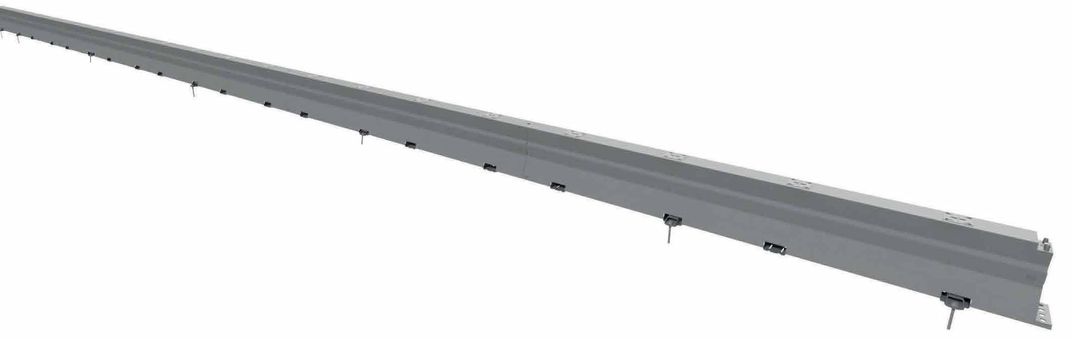
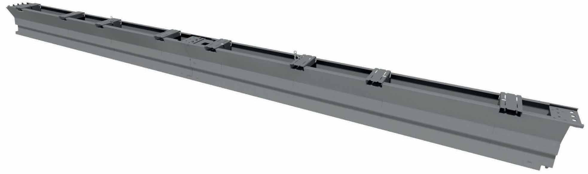
SafeZone™ is a smooth faced modular vehicle restraint system, anchored to the ground at the end of each run or at intermediate anchor points along its length as required to meet site-specified performance requirements. The closed design feature of SafeZone™ eliminates snag points providing consideration for vulnerable road users.
SafeZone™ comprises single, prefabricated 5.8m elements. Two (2) elements are bolted together at the factory prior to deployment, providing 11.6m long sections with male and female Quick Mount connectors to facilitate rapid onsite assembly. Fast connection of the elements is achieved by lining up the barrier and locking the Quick Mount connectors together.
The symmetrical design of SafeZone™ enables it to be deployed as either a single- or double-sided barrier providing protection for verge and median applications. The barrier may be secured to concrete and asphalt road surfaces.
The maximum length of the system is unlimited as the barrier relies upon the combination of torsional rigidity, anchoring and system mass to provide safe vehicle containment and redirection.
The anchoring frequency of SafeZone™ may be adjusted to provide three (3) configuration options:
1. SafeZone™ Standard;
2. SafeZone™ LDS; and 3. SafeZone™ MDS.
1. 2. Deflection Chart
1.3. Design Considerations
Pavement Grading
It is recommended that the slope of the pavement not exceed a grading of 8% to facilitate controlled vehicle containment and redirection.
Dynamic Deflection
Dynamic deflection is the maximum lateral displacement of the barrier during a vehicle impact. When a vehicle strikes a barrier, the dynamic deflection varies according to the characteristics of the impacting vehicle, including vehicle mass, impact speed, angle of impact and the characteristics of the barrier system. Sufficient dynamic clearance should be provided between the face of the barrier and a hazard to accommodate the appropriate dynamic deflection.
Working Width
4m
3m
2m
The working width is the minimum distance required to prevent an impacting design vehicle from colliding with an object behind a barrier system. This includes both the dynamic deflection of the barrier and the extra width to allow for the roll (vertical rotation) of an impacting vehicle. Working width is an important design consideration when shielding above-ground fixed hazards such as trees, sign supports or bridge piers. Above Gound Hazard
1.4. SafeZone™ Standard
SafeZone™ Standard provides an economical solution for worksites with sufficient clearance behind the system to accommodate expected barrier deflection and working width. The spacing of the anchors is 69.6m allowing the system to be rapidly installed, reducing drilling frequency and subsequent disruption to traffic.
1.5.
SafeZone™ LDS
SafeZone™ Low Deflection System (LDS) features a reduction in the spacing of anchors resulting in lower dynamic deflections and working widths. This is an import design consideration when workers or fixed hazards are located within close proximity to the barrier.
1.6. SafeZone™ MDS
SafeZone™ Minimum Deflection System (MDS) is designed for constrained sites that cannot accommodate the deflections and working widths of SafeZone™ LDS. The spacing of the anchors is reduced to just 5.8m, increasing the stiffness of the system. While providing lower dynamic deflection results, a Minimum Deflection System (MDS) increases the potential for vehicle occupant risk during high-speed impacts due to the increased stiffness of the barrier. It is therefore recommended that MDS installations be limited to constrained sites and undergo risk assessment analysis when preferred to Low Deflection System (LDS) options. The frequency of anchoring throughout the installation may revert to the nominated spacings for SafeZone™ LDS or SafeZone™ Standard where there is sufficient hazard free clearance behind the barrier.
SafeZone TL4 Standard Installation
Safezone TL4 Limited Deflection Installation
1.7. Table of curvatures
Method
1 Movement on Quick Connect
2 5 degree angle piece
3 10 degree angle piece
radius using only standard barriers: 528.0m
radius achievable using only 10° angle pieces: 11.2 m
Depending on the arc length any radius between 11.2m – ∞ can be achieved using the parts in the table above For job specific analysis contact your supplier.
1.8. Delineators
Reflective delineators can be attached to the side wall of the SafeZone™ as required and at the relevant spacings. There are two options of delineators available, one a fixed reflector the second a reflector with a flexible joint which helps makes it resistant to breaking. Reflectors can be also attached on top of the barrier.
2. Safety Statements
2.1. Lifting Safe Zone
Use lifting equipment that apply to local regulations.
Each standard element of SafeZone is 5.8m long and weighs approx. 535kg. It is supplied with two elements bolted together to form one 11.6m unit. The connection of the elements was made by lowering one element over the other. These barrier sections are connected together with male to female pin joints and then locked with a single security bolt. The weight of one unit is approx. 1,070kg. The standard barrier sections have 3 different lifting options, 1 position for lifting with a forklift and 2 positions for lifting with a crane using chains and hooks.
Make sure the chains are not twisted before hooking on. When hooking on to the barrier, make sure the hook is around the bar that runs across the slot. NEVER HOOK ON TO THE SHEET STEEL DIRECTLY. Make sure the hooks face outwards, i.e. the open side of the hook nearest the end of the barrier. Make sure the properly rated chain + hook for the load.
2.2. Turning the barrier over
In order to stack the barrier it is occasionally necessary to invert the barrier. Do not turn the barrier over by pulling it sideways with the crane. This can cause damage to the crane and chains, which could cause an accident due to failure during subsequent lifting operations. The following method can be used but note that the chain hooks are subject to side load when using this method. Always, therefore, use hooks that are rated at or above (typically 2,000 kg per hook)and use of the conventional type, not the type where the chain attaches to the extended latching bar.
Chapter 14/15/16 Lifting guide
2.3. Inverting the SafeZone
Lower the barrier onto a wooden block so that the barrier settles on the block near the center of the barrier clear of cross members and with only one side of the barrier supported by the block. Continue lowering the barrier until it lies on it’s side. Transfer the chains from the lifting eyes on the top of the barrier to the lifting eyes on the bottom of the barrier and lift the inverted barrier.
2.4. Righting inverted SafeZone
Lower the barrier onto a timber wedge with approximately a one in three slope. The barrier will settle on it’s side. Transfer the lifting chains from the bottom of the barrier to the top of the barrier and lift in the normal way.
2.5. General Safety
• All required traffic safety precautions should be followed. All workers should wear required Personal Protective Equipment (PPE)(OSHA approved vest, steel toed boots, eye protection, gloves).
• Only authorised trained personnel should operate any machinery. Where overhead machinery is used, care must be taken to avoid overhead hazards.
• There are no underground services, waterproof membranes etc. which could be damaged by drilling;
• There are no overhead cables that could be contacted by the lifting operation.
• There is adequate working room and safety zone.
3. Impact attenuators and transitions
Depending on state installation requirements SafeZone must start and finish with an approved impact attenuator or end terminal. Details of Impact attenuator transitions and connections are available from the Impact attenuator supplier.
Refer to annex 2 for approved impact attenuators and transitions.
SafeZone 11.6m section, male/female QuickLink, a unit
SafeZone anchor shoe (AS31840020)
SafeZone Threaded rod 300mm (KE31840030)
SafeZone™with a crash cushion end treatment. Transition should be fitted prior to the Crash Cushion installed. Per the manufacturer’s guidelines.
All M20 bolts to be used for connecting sections of SafeZone together to be at least grade 8.8. torque:200Nm (148 ft - lb).
SafeZone Flat top pin (AS31642592)
SafeZone Threaded rod 175mm (KE31840031)
SafeZone Excalibur bolt 300mm
5. Anchor Foundation Specifications & Material Specifications
5.1. Anchor Foundation Specifications
The SafeZone system has been designed to attach to concrete or asphalt foundations. Use the anchorage specified on page 10, depending on the foundation at the specific job site. Other foundations than listed below are not allowed.
Foundation:
Min 150mm reinforced pad or 200mm non reinforced pad
2. Asphalt over Base
3. Asphalt only
4.
250/500mm
Foundation:
Min 150mm AC over 100 or 350mm compacted Base
100mm (anchor type B)
350mm (anchor type A)
Foundation:
Min 250mm AC
250mm (anchor type B)
500mm (anchor type A)
Foundation: A Cover Concrete Total
1. Concrete Pad
Asphalt over Concrete
5. AASHTO Soil
6. Flush seal over granular pavement
5.2. Material Specifications
Portland Cement Concrete (PCC) Stone aggregate concrete mix, 25MPa minimum compressive strength. N25 per AS1379 sampling and testing per AS1012.
Compacted (Sub)Base (DGA) Densely Graded Base course as per local authority standards. 45mm aggregate maximum
CBR≥80%
Note: in case of other pavement specifications please consult manufacturer for advice.
Required Tools
7. Anchoring options on asphalt and concrete
7.1. Foundation Type
Suitable foundation type for Standard System
Note: in case of concrete decks thinner than 250mm please consult manufacturer for advice.
7.2. Choice of anchoring
Type 1 Anchor shoe standard (AS31840020)
6.
Tape measure Torque wrench Drill
Socket wrench Hammer T-Wrench
Mortar dispenser
Thermometer
Lifting Chain
7.3. Anchor Pin
Anchor Pin Type
Type A
Flat top pin Ø 30mm Length: 520mm
Type B
Threaded Rod Ø 30mm Length: 300mm
Type C
Threaded Rod Ø 30mm Length: 175mm
Type D
Excalibur Bolt Ø 20mm Length: 300mm
NOTE:
Hole
(AS31642592) Ø30mm 500mm depth
(KE31840030) Ø35mm 250mm depth
(KE31840031) Ø35mm 125mm depth
(not known) Ø20mm 280mm depth
Shoe Type Traffic Side Non Traffic Side
Type 1
Type 1
Type 1
Type 1
• Type B anchor pin is a chemical set anchor. Please refer to chapter 10.8 - 10.18 for instructions how to install these chemical anchor pins. Follow the instructions of chapter 7 for anchor distance for the standard installation when using type B anchor pins.
• Type D anchor used for Standard SafeZone TL3 only
7.4. Alternative anchoring systems
Alternative anchoring systems can be used to anchor SafeZone into concrete. Alternative anchoring systems need to comply with the required minimum pull and shear capacity as described below or need an individual approval from the barrier supplier. For the SafeZone Standard System and LDS System in concrete the following minimum anchor capacity is required:
• Pull force capacity, minimum, non-cracked concrete: NRk,c = 82kN (unfactored) or NRd,c = 55kN (factored) (concrete cone failure based on C25/30 EN206)
• Pull force capacity, minimum, cracked concrete: NRk,c = 58kN (unfactored) or NRd,c = 39kN (factored) (concrete cone failure based on C25/30 EN206)
• Shear force capacity, minimum: VRk,s = 225 kN (unfactored) or VRd,s = 180 kN (factored) (steel failure)
8. Standard installation on asphalt using pin type A
8.1. Start with standard SafeZone barrier section (AS31840000)
The standard installation is anchored on both ends by means of 4 anchors on each end. The minimum installation length of SafeZone Standard System is 69.63 m.
8.2. Beginning of first string of barriers
Startposition
8.3. The male coupling including the security bolt must face down stream
size: m20
length: 80mm
socket size: 30mm
8.4. Lower one element over the other
8.5. Lock the sections together with the security bolt using the ratchet or T-wrench
size: m20
length: 80mm
socket size: 30mm torque: 200 Nm (148 ft-lb
8.6. Finishing alignment of SafeZone and start anchoring first element
8.7. Insert the anchor plates (AS31840020)
8.8. Marking the drilling location (left and right side)
8.9. Drilling the holes (left and right aside)
8.10.
8.11. Placing anchor plates
After cleaning the holes the anchor plates must be placed in position again. The anchor plates are well positioned when they click in their position and can’t be moved from front to back or left to right.
8.12. Insert pins (AS31642592)
Insert the anchor pins by using a sledge hammer. Make sure all anchor pins are completely inserted so there’s no space between the pin and the anchor plate
The drilled holes must be blown out from the base of the hole 2 times with a suitable nozzle attachment (oil free compressed air > 87 Psi (6bar).
Clean the drilled holes (left and right side)
Finished first element
After complete anchoring of the first element move to the last element.
8.14. Anchor the last element as well 8.15. Completed SafeZone system
After complete anchoring the last element the system is completed.
The standard installation requires 4 anchors at the first and last element and 1 anchor every 69.6meter. Make sure there are always 10 unanchored elements in between. Use the second or third opening of the element for anchoring.
8.13.
9. SafeZone Limited Deflection System
9.1. General
The SafeZone Limited Deflection System is a specially configured system with a decreased anchor distance, this system offers a very low working width. The SafeZone LDS configuration increases the usable workspace in which to carry out construction and maintenance work and still perform to a high containment level. It is particularly beneficial to contractors working on tight construction sites to allow maximum working space together with full safety guideline compliance.
9.2. Installation
A length of SafeZone Limited Deflection System is built up by standard Units of SafeZone with anchor plates every 11.6m.
3 Rules for Anchoring:
1. Start with 2 anchor shoes / 4 anchors.
2. Install 1 anchor shoe / 2 anchors at 11.6m (38’) center to center.
3. Install 2 anchor shoes /4 anchors in the last element of the string at the location of the 2nd and 4th opening as per image above.
10. Anchoring options on asphalt and concrete for Limited Deflection System
10.1. Foundation Type
Suitable foundation type for Limited Deflection System:
Note: in case of concrete decks thinner than 300mm please consult manufacturer for advice.
10.2. Choice of anchoring
Type 1 Anchor shoe standard (AS31840020)
10.3. Anchor Pin
Rod Ø 30mm Length: 300mm
C
Threaded Rod Ø 30mm Length: 175mm
11. SafeZone Limited Deflection System installation using pin type B
11.1. Start with standard SafeZone barrier section (AS150145-0421)
SafeZone Limited Deflection System is a standard installation of SafeZone with anchor plates postioned every 11.6m. The minimum installation length of SafeZone Limited Deflection System is 69.63 m.
11.2. Beginning of first string of barriers
11.3. The male coupling including the security bolt must face down stream
size: m20
length: 80mm
socket size: 30mm
11.4. Lower one element over the other
11.5. Lock the sections together with the security bolt using the ratchet or T-wrench 11.6. Finishing alignment of
11.7. Insert the anchor plates (AS31840020)
Anchor plates are positoned every 11.6m for the Limited Deflection System, refer to step 20. The anchor plates are well positioned when they click in their position and can’t be moved from front to back or left to right.
11.8. Marking the drilling location
After placing the anchor plates, the 35mm drill can be applied through the anchor holes in the anchor plates to mark the exact position.
11.9. Drilling the holes
After marking the holes the anchor plates can be removed again for easy drilling. The holes must be drilled to a depth of 250mm and a diameter of Ø35mm.
11.6m(38.0ft)
11.10. Clean the drilled holes to ensure a good adhesion of the chemical mortar to the asphalt
11.11. Brush the drilled hole twice with a special stee lbrush FIS BS Ø35mm in combination with a power tool 11.12. Blow out the
The drilled holes must be blown out from the base of the hole 2 times with a suitable nozzle attachment (oil free compressed air > 87 Psi (6 bar).
The drilled holes must be blown out from the base of the hole 2 times with a suitable nozzle attachment (oil free compressed air > 87 Psi (6 bar).
11.13. Placing anchor plates
After cleaning the holes the anchor plates must be placed in position again. The anchor plates are well positioned when they click in their position and can’t be moved from front to back or left to right.
11.14. Measure the ground (hole) temperature
Measure the ground (hole) temperature before anchoring because this could influence the working and curing time of the mortar. For correct temperature check the instructions from the mortar manufacturer.
11.15. Prepare mortar cartridge
We recommend using Fischer SIB 390 S. When not available use an alternative mortar with the same corresponding characteristics and behavior. When using an alternative mortar follow the installation description from the supplier / manufacturer to achieve the same results.
1. Remove the cap from the cartridge by turning and pulling it off.
2. Attach the static mixer, tighten it firmly and lock it in place (turn to right).
3. Place the cartridge in the dispenser.
4. Press approx. 10cm of material out until theres in mortar comes out in evenly grey colour. Mortar which is not grey colour will not cure and must be disposed of.
We recommend using Fischer SIB 390 S. When not available use an alternative mortar with the same corresponding characteristics and behavior. When using an alternative mortar follow the installation description from the supplier / manufacturer to achieve the same results.
11.16. Fill the hole with injection mortar
Fill the drill hole with injection mortar starting at the bottom, make sure that it does not contain any air bubbles, +/- 110ml per anchor hole.
11.17. Insert threaded rod (KE31840030)
Anchoring pin must be straight and free of oil and other contaminants. Mark the anchor with correct embedment depth 250mm. Press the anchor pin down to the bottom of the hole, turning its lightly while pressing. After inserting the pin, excess mortar must emerge from the mouth of the hole. If no mortar appears at the surface of the hole, the anchoring pin must be removed immediately and mortar must be injected again. Do not disturb the anchoring element until cure time has elapsed.
11.18. Tighten nut after mortar has hardened
size: m30
socket size: 46mm torque: 300Nm (220ft-lb)
Torque the M30 hex nuts including flat washer on the anchor studs after curing time has elepased, torque toappr. 106Nm (78ft-lb) for asphalt and 300Nm (220ft-lb) for concrete.
11.19. Remember to anchor the last element as well
Install 2 anchor shoes / 4 anchors in the last element of the string at the location of the 2nd and 4th opening.
11.20. A length of SafeZone Limited Deflection Sytem is built up with anchor plates every 11.6m
11.21. Completed SafeZone Limited Deflection System
12. SafeZone Minimum Deflection System
12.1. General
The SafeZone Minimum Deflection System is a specially configured system with a decreased anchor distance, this system offers a very low working width. The SafeZone MDS configuration increases the usable workspace in which to carry out construction and maintenance work and still perform to a high containment level. It is particularly beneficial to contractors working on tight construction sites to allow maximum working space together with full safety guideline compliance.
12.2. Installation
A length of SafeZone Minimum Deflection System is built up by standard Units of SafeZone with anchor plates every 5.8m.
3 Rules for Anchoring:
1. Start with 2 anchor shoes / 4 anchors.
2. Install 1 anchor shoe / 2 anchors at 5.8m (19’) center to center.
3. Install 2 anchor shoes /4 anchors in the last element of the string at the location of the 2nd and 4th opening as per image above.
13. Anchoring options on asphalt and concrete for Minimum Deflection System
13.1. Foundation Type
foundation
Note: in case of concrete decks thinner than 300mm please consult manufacturer for advice.
13.2. Choice of anchoring
Type 1 Anchor shoe standard (AS31840020)
13.3. Anchor Pin
14. SafeZone Minimum Deflection System installation using pin type B
14.1. Start with standard SafeZone barrier section (AS150145-0421)
SafeZone Limited Deflection System is a standard installation of SafeZone with anchor plates postioned every 11.6m. The minimum installation length of SafeZone Limited Deflection System is 69.63 m.
14.2. Beginning of first string of barriers
14.3. The male coupling including the security bolt must face down stream
size: m20
length: 80mm
socket size: 30mm
14.4. Lower one element over the other
14.5. Lock the sections together with the security bolt using the ratchet or T-wrench
14.7. Insert the anchor plates (AS31840020)
5.8m(19.0ft)
Anchor plates are positoned every 11.6m for the Limited Deflection System, refer to step 20. The anchor plates are well positioned when they click in their position and can’t be moved from front to back or left to right.
14.8. Marking the drilling location
After placing the anchor plates, the 35mm drill can be applied through the anchor holes in the anchor plates to mark the exact position.
14.9. Drilling the holes
After marking the holes the anchor plates can be removed again for easy drilling. The holes must be drilled to a depth of 250mm and a diameter of Ø35mm.
14.10. Clean the drilled holes to ensure a good adhesion of the chemical mortar to the asphalt
14.11. Brush the drilled hole twice with a special stee lbrush FIS BS Ø35mm in combination with a power tool 14.12. Blow out the
The drilled holes must be blown out from the base of the hole 2 times with a suitable nozzle attachment (oil free compressed air > 87 Psi (6 bar).
The drilled holes must be blown out from the base of the hole 2 times with a suitable nozzle attachment (oil free compressed air > 87 Psi (6 bar).
14.13. Placing anchor plates 14.14. Measure the ground (hole) temperature
After cleaning the holes the anchor plates must be placed in position again. The anchor plates are well positioned when they click in their position and can’t be moved from front to back or left to right.
Measure the ground (hole) temperature before anchoring because this could influence the working and curing time of the mortar. For correct temperature check the instructions from the mortar manufacturer.
14.15. Prepare mortar cartridge
We recommend using Fischer SIB 390 S. When not available use an alternative mortar with the same corresponding characteristics and behavior. When using an alternative mortar follow the installation description from the supplier / manufacturer to achieve the same results.
1. Remove the cap from the cartridge by turning and pulling it off.
2. Attach the static mixer, tighten it firmly and lock it in place (turn to right).
3. Place the cartridge in the dispenser.
4. Press approx. 10cm of material out until theres in mortar comes out in evenly grey colour. Mortar which is not grey colour will not cure and must be disposed of.
We recommend using Fischer SIB 390 S. When not available use an alternative mortar with the same corresponding characteristics and behavior. When using an alternative mortar follow the installation description from the supplier / manufacturer to achieve the same results.
14.16. Fill the hole with injection mortar
Fill the drill hole with injection mortar starting at the bottom, make sure that it does not contain any air bubbles, +/- 110ml per anchor hole.
14.17. Insert threaded rod (KE31840030)
Anchoring pin must be straight and free of oil and other contaminants. Mark the anchor with correct embedment depth 250mm. Press the anchor pin down to the bottom of the hole, turning its lightly while pressing. After inserting the pin, excess mortar must emerge from the mouth of the hole. If no mortar appears at the surface of the hole, the anchoring pin must be removed immediately and mortar must be injected again. Do not disturb the anchoring element until cure time has elapsed.
14.18. Tighten nut after mortar has hardened
size: m30
socket size: 46mm torque: 300Nm (220ft-lb)
Torque the M30 hex nuts including flat washer on the anchor studs after curing time has elepased, torque toappr. 106Nm (78ft-lb) for asphalt and 300Nm (220ft-lb) for concrete.
14.19. Remember to anchor the last element as well
14.20. A length of SafeZone Minimum Deflection Sytem is built up with anchor plates every 11.6m
14.21. Completed SafeZone Minimum Deflection System
15. Maintenance and repair
SafeZone™ has an estimated 20-years life cycle. With years of experience with BarrierGuard 800 and through rigorous testing SafeZone sections have proven to be very robust and extremely hard wearing. We recommend some very basic maintenance schedules detailed below. SafeZone sections should be thoroughly inspected prior to dispatch to the job site, during the inspection make sure that all the fasteners are present, there is no sign of damage to the Quick Connect and that there is no creases or dents in the barrier that could prevent it connecting together during the installation. If any of the above faults are detected then the damaged section or sections of barrier should marked and put to one side for further assessments to take place and repairs made before the section of SafeZone is used again.
SafeZone is predominantly used for road work situations. There is usually personnel driving through the site, and also as the barrier is usually only installed for mediumor short term it can be regularly inspected as it is returned to storage and again inspected as it is dispatched to the next job site. The installer can determine a suitable detection interval in connection with accident rated and traffic flow on the relevant route.
The drive by inspection is usually achievable by driving fairly slowly along the length of the installed barrier, depending on the location and site conditions then this may require additional safety systems put in place for example traffic management. During this inspection checks should bemade for any damage to the barrier caused by an impact. If there are signs of an extreme impact then amore thorough inspection should be carried out as soon as possible. The barrier sections will need to be replaced in the installation and the damaged sections taken away for further analysis.
Any fasteners that need replacing must meet the correct specification and performance; the bolts must have an 8.8 strength classification (ASTM F1554 Grade 105) and be the correct type of fastener for the application.
Although tears and deep scratches normally do not affect the performance of the barrier system it should be remembe- red that this may introduce corrosion to the barrier units, so the application of a protective coat of zinc rich paint maybe necessary locally in the area of the damage. In case of deep scratches the barrier unit should be replaced. Do not use any sections of barrier that show signs of significant thinning of the barrier skin caused by corrosion.
16. Removal
Refer to below steps for barrier removal.
• Step 1a: Removal of anchor Type A can be achieved by lifting the barrier section itself with a crane or forklift, the anchor pins will come out with the barrier.
• Step 1b: Removal of anchor Type B and can be achieved by either adding a 2nd nut on top of the anchor rod and clamping it or spot welding the existing nut to the anchor rod and rotating the system counter clockwise with an impact wrench.
• Step 2: Remove the security sets
• Step 3: Removal of the individual barrier elements is a reversal of the installation procedure. To separate the barrier sections, start at the last installed element and lift the element keeping it in a horizontal position. The barrier element will separate from the adjacent element. If the section of barrier being removed also lifts the adjacent section with it, place a 50mm high block under the foot of the section being removed (next to the joint), and lower the barrier. It will then separate. The string of barrier elements can also be split anywhere within the string, to allow for another removal point. This can be achieved by lifting an intermediate barrier section and rotating the free end sideways, outside of the barrier string.
• Step 4: Make sure that the bolt on the security set is tightened before transportation.
• Step 5: After removing the barrier elements the remaining anchor holes should be filled. For quick repairs it is advisable to use a one application product like a cold asphalt mix without the need for application of a tack coat, suitable for all weather conditions and which is immediately trafficable. For details on materials and procedures for repairing the road deck surface contact local asphalt specialists. For regulations consult the local road authorities.
17. Permanent installations
Both SafeZone and SafeZone LDS are appropriate as a permanent solution using threaded rod Type B anchors only. Make sure only approved permanent crash cushions are installed for permanent use, do not use temporary crash cushions.
Inspection period for permanent installations
• We suggest that this inspection is carried out at 3 year intervals after the first inspection. Please check with your local jurisdiction if their routine inspection periods are different and go with the lesser period.
Maintenance and inpection
The same methodology would apply for the maintenance of permanent installations as to temporary installations however a number of extra steps should be taken during inspection of permanent installations.
• Inspect for damage.
• Please check anchor shoe housing of barrier if impact has taken place. Inspect the anchor shoe housing to make sure it’s still intact and that there has been no tearing of the steel. If damaged replace barrier.
• Please check joint of barrier if impact has taken place. Check that the coupling of the barrier is not damaged. If coupling is damaged replace barrier as necessary.
• Check for alignment. Check that the barrier is in the correct location. Look along length of run and check that each barrier is not sticking out from the next one (Visual check. Replace or re-install if required)
• Check for joints connected correctly Inspect. Check that the M20 Nut is in place. Check that the M20 Nut is hand tight. (Replace or re-install if required)
• Check Anchored to ground Inspect. Check fixings to anchors are still in place. For threaded rod type anchors make sure that the nut is in place and is hand tight (Re-install if required)
• Check for debris around barrier (remove if required)
• Check delineation intact. Check that all delineators are still in place. Check that none are loose. (Inspect and replace if required)
• Check for graffiti. Use paint thinner or graffiti removal products if required? (Clean if required)
• Check for corrosion. If corrosion has formed on the outside of barrier it may be necessary to inspect the barrier internally. Please check with manufacturer for further instructions if this scenario occurs.
18. Limitations and warnings
SafeZone™has been rigorously tested and evaluated per the evaluation criteria in the MASH guidelines for a longitudinal barrier. The impact conditions recommended in MASH are intended to address typical inservice collisions.
When properly installed and maintained SafeZone™allows an impacting vehicle to be contained or re-directed in a safe and predictable manner under the MASH impact conditions. Vehicle impacts that vary from the MASH impact conditions described for longitudinal barriers may result in significantly different results than those experienced in testing.
5.8m barrier Always follow the manufacturers instruction for correct use of the clutch. Shorten the chain using the clutch to ensure the load is level. Single Element 535.0 kg Use a suitable crane accorrding offical lifting capacity regulations.
19. Lifting guide 5.8m barrier
19.1. Lifting the 5.8m barrier from the top
19.2. Lifting the 5.8m barrier from the bottom
20.
11.6m barrier Always follow the manufacturers instruction for correct use of the clutch. Shorten the chain using the clutch to ensure the load is level.
Doouble Element 1070.0 kg Use a suitable crane accorrding offical lifting capacity regulations.
Lifting guide 11.6m barrier
20.1. Lifting the 5.8m barrier from the top
20.2. Lifting the 5.8m barrier from the bottom
21. Lifting guide ForkLift
21.1. Lifting the 5.8m barrier with a forklift
21.2. Lifting the 11.6m barrier with a forklift
22. Marking
Use original SafeZone parts only. Barriers marked with this logo are SafeZone barriers.
(YY/MM/DD) - production number
The ingraving can be found here. See picture below
marking can be found here
Example Pre-installation checklist
SafeZone must be installed by a qualified installer, with written documentation signed at the end of the installation that it has been installed as per manufacturer manual.
The units are positioned on a cross fall of 8% / 3.60 or less.
All security bolts on the Quick Connect are attached and tightened.
Is an approved crash cushion required?
Workers and equipment are located in the CoPTTM safety clear zone.
Are all hazards located outside the clear zone?
Are all tools removed from site when installation is complete.
If delineation is required it is applied as per MoTSam Part 2.
Clear any debris from under and between the units.
Arrange maintenance inspections as appropriate for location.
Location:
Installed by:
Installed by:
Date:
Date:
Example Installation form
Please fill in and sign this form at the end of the installation.
Project name:
Job site address:
Time arrived:
Time completed:
Lengths of installs:
Components installed on site:
Anchoring:
End treatments:
Project manager/ site foreman:
Traffic control company:
Tool box meeting held:
Installers on site:
Installation checked by:
Location:
Installer certificate number:
Signed by qualified installer:
Date:
Date:
instructions, standard or limited deflection.
NOTES: UNLESS OTHERWISE SPECIFIED.
TAU-M foundation material, specifications and anchorage must be in accordance with LTS foundation specifications for concrete foundations. Reference LTS drawing A040113 & Installation Manual.
1. 2. 3.
TL-3 Model 30TM100CC shown,
TAU-M to be installed per manufacturer’s instructions. See assembly and installation manual for additional details.
TL-2 Model 30TM070CC may be installed in similar fashion.
SafeZone barrier to be installed per manufacturer’s instructions, standard or limited deflection.
2x THRIE BEAM BLOCKOUT PER AASHTO PDB02 LTS P/N: 4002050 (may be sourced through others) TRAFFIC TRANSITION BRACKET B050527 2x NESTED END PANELS GR80, TAU-M BSI-1708030-00
TAU-M foundation material, specifications and anchorage must be in accordance with LTS foundation specifications for concrete foundations.
Reference LTS drawing A040113 & Installation Manual. Blockouts per local standards. Blockout to be field trimmed to fit.
Transition panels, blockouts, custom bracket and thrie beam terminal connector attached through barrier with 16mm threaded rods (BSI-1309061-00) with beam washers (4002051), flat washers (2001636) and nuts (401116), threaded rod maybe field trimmed. Holes through barrier are 20mm.
Attach custom bracket to thrie beam terminal connector with 16mm x 50mm bolts (400115) with beam washers (4002051), flat washers (2001636) and nuts (4001116).
152mm MIN (REINFORCED) 203mm MIN (NON-REINFORCED) 889mm
LINE UNIVERSAL TAU-M FOUNDATION (see manual for details)
NOTES: UNLESS OTHERWISE SPECIFIED. UNIVERSAL TAU-M SYSTEM 30TM100CC
1. 2. 3. 4. 5. 6.
ANCHORING LOCATIONS BOTH SIDES
SAFEZONE BARRIER (provided by others) 2x NESTED UNIVERSAL TAU-M ANGLED END PANELS B040203 926mm TRAFFIC 7264mm MIN 5690mm 6734mm 6934mm
CUSTOM BRACKET P/N: TBD THRIE BEAM END SHOE AS PER AASTHO HARDWARE SPECIFICATION RTE01b. LTS P/N: 4002049 (may be sourced through others)
NOTES: UNLESS OTHERWISE SPECIFIED.
TAU-M to be installed per manufacturer’s instructions. See assembly and installation manual for additional details.
Model 30TM070CC may be installed in similar fashion.
TL-3 Model 30TM100CC shown, TL-2
SafeZone barrier to be installed per manufacturer’s instructions, standard or limited deflection.
TAU-M foundation material, specifications and anchorage must be in accordance with LTS foundation specifications for asphalt foundations.
Reference LTS drawing A040113 & Installation Manual. Blockouts per local standards. Blockout to be field trimmed to fit.
Transition panels, blockouts, custom bracket and thrie beam terminal connector attached through barrier with 16mm threaded rods (BSI-1309061-00) with beam washers (4002051), flat washers (2001636) and nuts (401116), threaded rod maybe field trimmed. Holes through barrier are 20mm.
Attach custom bracket to thrie beam terminal connector with 16mm x 50mm bolts (400115) with beam washers (4002051), flat washers (2001636) and nuts (4001116).
1. 2. 3. 4. 5. 6.
OTHERWISE SPECIFIED. TAU-M TO BE INSTALLED PER MANUFACTURER’S INSTRUCTIONS. SEE ASSEMBLY AND INSTALLATION MANUAL FOR ADDITIONAL DETAILS. TL-3 MODEL 30TM100CA SHOWN, TL-2 MODEL 30TM070CA MAY BE INSTALLED IN SIMILAR FASHION. SAFEZONE BARRIER TO BE INSTALLED PER MANUFACTURER’S INSTRUCTIONS, STANDARD OR LIMIT DEFLECTION. TAU-M FOUNDATION MATERIAL, SPECIFICATIOINS AND ANCHORAGE MUST BE IN ACCORDANCE WITH LTS FOUNDATION SPECIFICATIONS FOR ASPHALT FOUNDATIONS. REFRENCE LTS DRAWING A040113 & INSTALLATION MANUAL. 1. 2. 3.