CATALOGUE


Signfix® – New Zealand’s premier quality support and fixing systems for the road sign industry


Signfix® – New Zealand’s premier quality support and fixing systems for the road sign industry

BRACKETS & CLAMPS
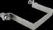
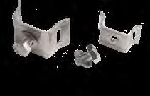
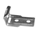
Structural aluminium alloy brackets that offer a robust fitting for small flat signs on 50mm NB and 65mm NB poles. Highly resistant to corrosion and impacts.
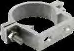
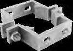
Signfix clamps, brackets and clips secure signs to posts of every shape and size. Signs installed using Signfix products offer greater on-site flexibility and can be offset with ease.
The stainless steel product range is manufactured using AISI 304 alloy, a highly durable material particularly beneficial when impact resistance and anti-corrosion is important.
The stainless steel fittings have been subjected to ASTM B117 salt-spray testing for 500 hours with no significant corrosion. They are highly suitable in coastal regions.
With a market presence of over 20 years, the Signfix range of superior quality products have proven longevity.


*LIGHT RECTANGULAR HOLLOW SECTION POSTS **HEAVY RECTANGULAR HOLLOW SECTION POSTS BOLT & NUT NOT INCLUDED
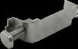
& CHANNEL BRACKETS

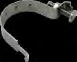
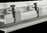
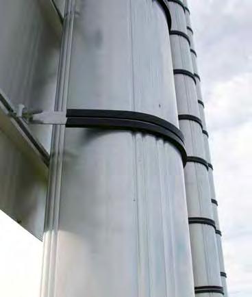
Signfix offers the sign industry the versatility of stainless steel bands and fittings specially designed and packaged for sign makers and installers. The premium quality stainless steel is compatible with other Signfix materials, suiting small to large diameter poles.
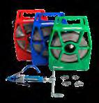
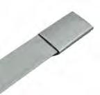
STR13, STR16, STR19 – to calculate the approximate amount of banding required, multiply the pole diameter by 3.14 or pi (π), then add on an extra 120mm for fixing with the Band-It Tool, e.g. 114mm OD pole x 3.14 = 358mm + 120mm = 478mm. Also available: 316 grade s/steel for coastal regions.


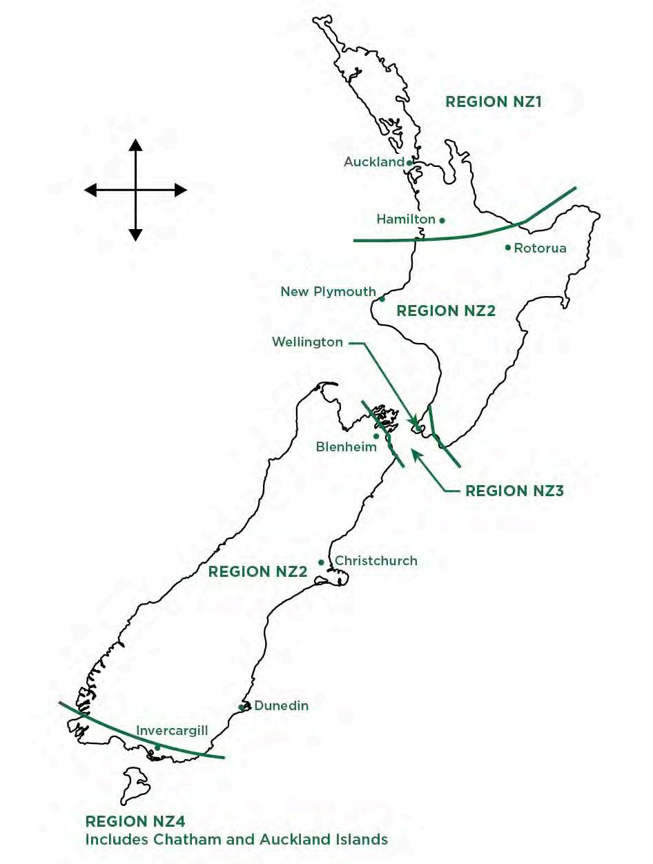
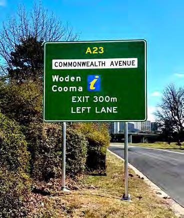
Signfix™ is the leading frangible aluminium signpost range and is used extensively by road authorities. In addition to its compliant passive safety features, Signfix is popular with construction contractors due to its lightweight design and ease of installation. The Signfix range can be installed as a single sign support or a multi leg assembly. The system allows up to 16m2 single sign dimensions in the major New Zealand wind zone regions. We are pleased to introduce Optimast® into the market,
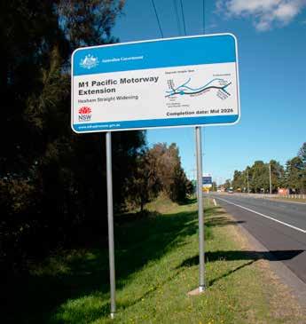
Signfix frangible poles range 76-114mm in outer diameter and hold up to 16m2 road signs in New Zealand wind regions.
> Signfix fluted poles come in 4.5m-6.5m lengths, depending on the pole diameter.
> Pole sizes: Ø76mm, Ø89mm, Ø102mm, Ø114mm.
> Poles inserted into corresponding sized aluminium ground sleeve sockets, set in concrete foundations.
> Ground sleeves vary 300-1000mm in length.
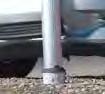
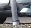
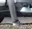
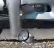
> Upon vehicle impact, the sleeve acts as a shear point, safely breaking away the pole at the socket top.
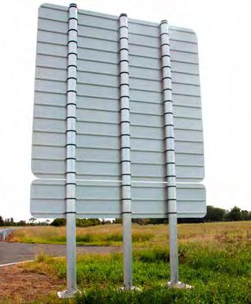
a complimentary frangible signpost range for larger sign dimensions of up to 40m2 across the major New Zealand wind regions. The increased signage area enables road designers and engineers to specify passive sign structures for large scale traffic messaging such as highway directional signage.
Both the Signfix and Optimast ranges are convenient out of the box products, thus requiring very little intervention from sign installation crews or civil engineers.
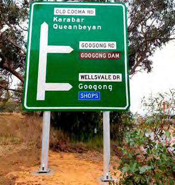
Optimast range 127-244mm in diameter and hold up to 40m2 road signs in New Zealand wind regions
> Optimast poles come in 5.0m-8.0m lengths, depending on the pole diameter.
> Pole sizes: Ø127mm, Ø168mm, Ø219mm, Ø244mm.
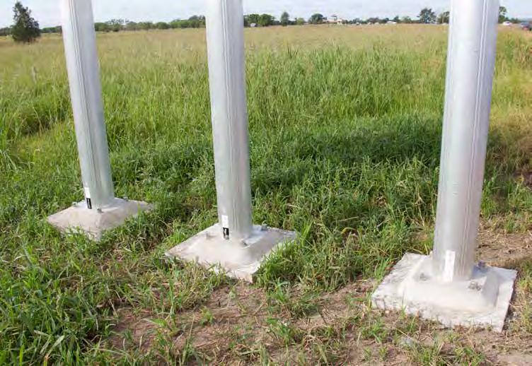
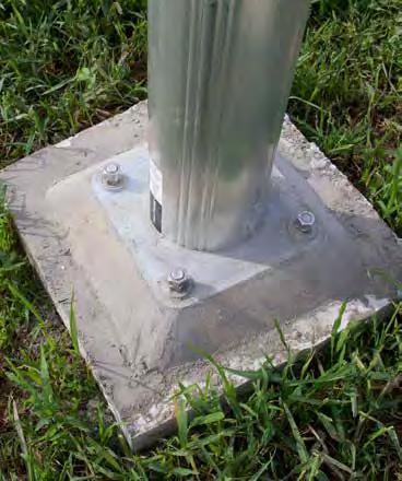
> Poles are affixed to base plates with shear bolts.
> The base plates are attached to anchor cradles set in concrete with foundation bolts.
> Upon vehicle impact, shear bolts safely breakaway the pole from the base plate.
Austroads, the peak body of Australasian road transport and traffic agencies, require new and existing road safety products to comply to the updated testing guidelines of AS/NZS3845.1 (2015) and AS/NZS3845.2 (2017). Road safety products must now be tested to the American Association of State Highway and Transport Officials (AASTO) 2009 Manual for Assessing Safety Hardware (MASH) guidelines. MASH testing supersedes NCHRP 350 testing for New Zealand road barrier products.
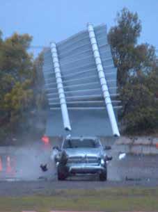
After extensive vehicle impact tests were undertaken on the Signfix and Optimast product ranges by a leading FHWA testing facility, the Signfix and Optimast product ranges are MASH compliant and approved by Austroads Safety Barrier Assessment Panel (ASBAP) for use on the New Zealand road network.
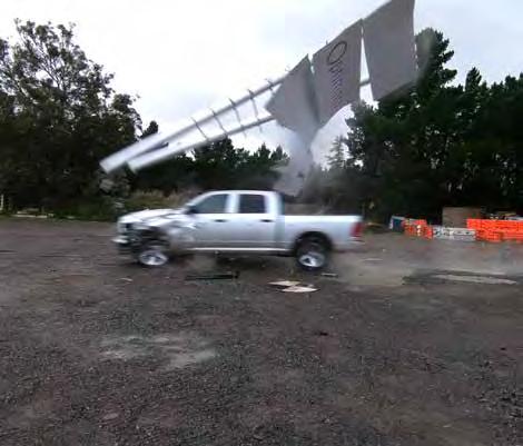
Signfix and Optimast product ranges are MASH compliant and approved by Austroads Safety Barrier Assessment Panel (ASBAP) for use on the New Zealand road network.
The post cap must be tted into the pole to reduce water ingress.
The ground sleeve seal must be tted to prevent dirt and water from entering the ground sleeve.
Bung for shear hole
Aluminium uted pole
Maximum 90mm
Stainless steel transition shoe must be tted and placed betweeen the pole and locking bolts with the locking evenly tightened between 10 --12 Nm
2 x M10 trilobular stainless steel set screws M12 retention bolt
Concrete foundation to local engineers speci cation
The requirement to meet stringent MASH testing guidelines have led to modifications of the Signfix frangible sign support product range as detailed below:
SIGNFIX NCHRP 350 COMPLIANT DESIGN (100NB)
Aluminium ground sleeve
Varies
Minimum 400mm Varies
Sleeve end cap
Product Codes
AFP114/6.5 SLV1141000
SIGNFIX MASH COMPLIANT DESIGN (100NB)
2 sealed apertures located 90o each side from facing traffic
Restraint bolt to secure sleeve and pole
Product Codes
AFPM114/6.5 SLVM1141000

> The patented Signfix fluted pole and socket system meets or exceeds the MASH testing thresholds for frangible structures.
> Successfully under taken rigorous impact testing with 1100kg and 2270kg vehicles at speeds of 30km/h and 100km/h by a leading FHWA accredited testing agency.
> Occupant Impact Velocity below the preferred 3.0m/s thresholds (4.9m/s maximum).
> Occupant Ride-down Deceleration well below the preferred 15.0g threshold.
> Deformations of vehicle occupant department and post impact vehicle trajectory within acceptable limitations.
> The lightweight extruded aluminium components are easy to handle and convenient to transport.
> Simple to install with no specialist equipment required – props are not required for installing ground sleeves and larger poles during the foundation hardening process.
> Damaged poles are easily removed, and replacement poles re-installed into existing sleeve foundations.
> Wind chart system allows installers to easily determine optimal pole configuration (number of poles and size).
> Clear instruction manuals provided.
> Structurally designed to support a sign area of up to 16m2
> The fluted pole diameter sizes fit all standard bracket types.
> Lightweight Signfix aluminium frangible poles are similar in strength to steel equivalents.
> Patented stainless-steel transition shoe is supplied to prevent wear and eliminate any electrolysis action between the locking bolts and pole.
> Revised MASH design range comes with polymer seals, plugs and caps to prevent water ingress.
> Corrosion resistance from high quality marine grade aluminium alloy.
The extruded aluminium mast is delivered assembled with shear bolts attached to the base plate
The foundation bolt arrangements range from:
>M16 (Ø127)
>M20 (Ø168, Ø219)
>M24 (Ø244)

The Anchor Cradle Assembly comprises of a pre-fabricated socket type anchor, a wooden ‘template’ that can be used for shuttering/battering purposes and 4 securing bolts. These bolts are used simply as an aid to cast the anchor cradle and as a means of preventing site debris from entering the socket(s).

> Proven performance in the UK, Germany and France, Optimast complies to BS EN 12767 and has achieved the highest safety accreditation, 100 NE3.
> The Optimast system meets or exceeds the MASH testing thresholds for frangible structures.
> Successfully under taken rigorous impact testing by a leading FHWA accredited testing agency.
> Occupant Impact Velocity below the preferred 3.0m/s thresholds (4.9m/s maximum).
> Occupant Ride-down Deceleration below the preferred 15.0g threshold.
> Deformations of vehicle occupant department and post impact vehicle trajectory within acceptable limitations.
> The extruded aluminium mast (5-8m lengths), shear bolts and base plate are delivered fully assembled.
> Simple to install base plate with foundation bolts onto an anchor cradle socket set into a concrete foundation.
> Easy to replace damaged poles, which are easily removed and re-installed onto existing foundations.
> Wind chart system allows installers to easily determine optimal pole configuration (number of poles and size).
> Clear instruction manuals provided.
> Structurally designed to support large directional signs of up to 40m2
> Signfix provides specialised Optimast clamps with rubber lining to affix mast to sign channel.
> Strong extruded aluminium cylindrical design has similar strength to steel equivalents.
> Corrosion resistant high-quality marine grade aluminium alloy.
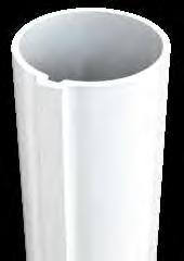
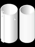
FLUTED ALUMINIUM POLES
The high-strength marine grade alloy used in 50NB Signfix fluted aluminium poles is light weight and has excellent corrosion resistance.
Standard pole lengths:
50NB (60OD) > 3.2m, 4.0m
ACCESSORIES AND COMPONENTS
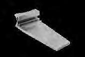
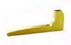
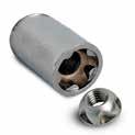
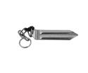
SLEEVE WEDGE
Standard zinc plated wedge. 60OD sleeves are designed to be fitted with a standard wedge, allowing sleeves to be installed flush at ground level.
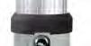
POLY POST CAP & POLY SLEEVE SEAL
To reduce water ingress the poly cap and poly seal tightly form firm fits at the top of the post and sleeve.
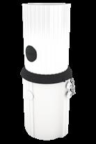
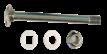
RESTRAINT BOLT
Securing the pole in the sleeve retained with a kinmar security nut and SS bolt.
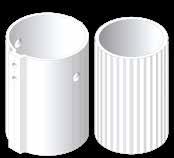
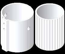
POWDER COATED ALUMINIUM GROUND SLEEVES
Designed to suit 50NB aluminium fluted and galvanised steel poles, Signfix ground sleeves are made from high strength marine grade alloy.

The alloy has excellent corrosion resistance and over the years has proven performance with aluminium frangible poles.
GROUND SLEEVE LENGTHS
50NB (60OD) > 300mm, 400mm, 450mm & 600mm
Features include:
> The external shape ensures sleeves will not rotate when set in concrete.
> Internal dimensions of all sleeves are designed to be a snug fit with the pole.
> Sleeves are fitted with PVC end caps to prevent concrete entering the sleeve during installation.
Sleeves can be supplied with an M8 tapped hole located 15mm below the sleeve top, to fit either an M8 hex bolt or a trilobular security set screw. This option is ideal for securing PVC poles and in this instance, it is recommended that the sleeves are placed 30mm above ground level.

CODE DESCRIPTION
AFP060/3.2NZ 50MM NB X 3.2M ALUM FLUTED POLE WHITE FINISH
AFP060/4NZ 50MM NB X 4.0M ALUM FLUTED POLE WHITE FINISH
SLV060300NZ 50MM NB X 300MM ALUM GROUND SLEEVE FOR 50MM NB POLE WHITE FINISH
SLV060300-DTNZ 50MM NB X 300MM ALUM GROUND SLEEVE FOR 50MM NB POLE WHITE FINISH DRILLED & TAPPED W TRILOB
SLV060400NZ 50MM NB X 400MM ALUM GROUND SLEEVE FOR 50MM NB POLE WHITE FINISH
SLV060400-DTNZ 50MM NB X 400MM ALUM GROUND SLEEVE FOR 50MM NB POLE WHITE FINISH DRILLED & TAPPED W TRILOB
SLV060450NZ 50MM NB X 450MM ALUM GROUND SLEEVE FOR 50MM NB POLE WHITE FINISH
SLV060450-DTNZ 50MM NB X 450MM ALUM GROUND SLEEVE FOR 50MM NB POLE WHITE FINISH DRILLED & TAPPED W TRILOB
SLV060600NZ 50MM NB X 600MM ALUM GROUND SLEEVE FOR 50MM NB POLE WHITE FINISH
SLV060600-DTNZ 50MM NB X 600MM ALUM GROUND SLEEVE FOR 50MM NB POLE WHITE FINISH DRILLED & TAPPED W TRILOB
SLVWEDGE060 GROUND SLEEVE WEDGE
POLYCAP060 50MM NB POLY POST CAP
POLYSEAL060 50MM NB POLY SLEEVE SEAL
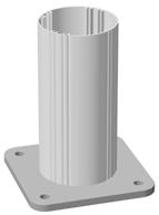
POWDER COATED ALUMINIUM POLES
The high-strength marine grade alloy used in 80NB, 90NB and 100NB Signfix fluted aluminium poles is light weight and has excellent corrosion resistance.
Standard pole lengths:
65NB (76OD) > 4.5m lengths
80NB (89OD) > 5.5m lengths
90NB (102OD) > 6.0m lengths
100NB (114OD) > 6.5m lengths
ACCESSORIES AND COMPONENTS
SLEEVE WEDGE
76OD sleeves are designed to be fit with a standard wedge, alllowing sleeves to be installed flush at ground level.
TRANSITION WEAR SHOE
80NB, 90NB and 100NB sleeves are designed to be fit with a transition shoe & two trilobular fasteners.
The patented stainless steel transition shoe fits between the aluminium pole wall and M8 trilobular locking bolts, to prevent fracture points and eliminate any electrolysis action. The innovative stainless steel transition shoe MUST be placed between the pole and locking bolts and tightened evenly between 10 and 12 Nm.
POLY POST CAP & POLY SLEEVE SEAL
To reduce water ingress the poly cap and
poly seal tightly form firm fits at the top of the post and sleeve.
RESTRAINT BOLT (KINMAR)
Calibrated to secure a pole and sleeve to shear safely through stringent MASH vehicle impact tests.
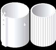
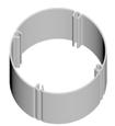
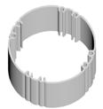
POWDER COATED ALUMINIUM GROUND SLEEVES
Designed to suit 80NB, 90NB and 100NB aluminium frangible poles, Signfix ground sleeves are made from high strength marine grade alloy. The powder coated sleeve has excellent resistance to corrosion and over the years has proven performance with our aluminium poles.
GROUND SLEEVE LENGTHS
65NB (76OD) > 750mm lengths
80NB (89OD) > 750mm lengths
90NB (102OD) > 850mm lengths
100NB (114OD) > 1000mm lengths
Features include:
> The external shape ensures sleeves will not rotate when set in concrete.
> Internal dimensions of all sleeves are designed to be a snug fit with the pole.
Sleeves are fitted with PVC end caps to prevent concrete entering the sleeve during installation.
POLES, SLEEVES & ACCESSORIES

80NB
CODE
DESCRIPTION
AFPM089/5.5MNZ 80MM NB X 5.5M ALUM FLUTED POLE WHITE FINISH
SLV089750MNZ 80MM NB X 750MM ALUM GROUND SLEEVE FOR 80MM NB POLE WHITE FINISH
POLEKIT089M 80NB KIT SET C/W POLYCAP089, POLYSEAL089, POLYPLUG089 X 2, M12 X 119MM RESTRAINT BOLT, KINMAR NUT, NYLON WASHER X 2
POLYCAP089 80MM NB POLY POST CAP
POLYSEAL089 80MM NB POLY SLEEVE SEAL
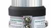
KINMARSOCKETM KINMAR DRIVE SOCKET - M12
M – Denotes MASH range
CODE DESCRIPTION
AFP102/6MNZ 90MM NB X 6M ALUM FLUTED POLE WHITE FINISH
SLV102850MNZ 90MM NB X 850MM ALUM GROUND SLEEVE FOR 90MM NB POLE WHITE FINISH
POLEKIT102M 90NB KIT SET C/W POLYCAP102, POLYSEAL102, POLYPLUG102 X 2, M12 X 133MM RESTRAINT BOLT, KINMAR NUT, NYLON WASHER X 2
POLYCAP102
POLYSEAL102
90MM NB POLY POST CAP
90MM NB POLY SLEEVE SEAL
KINMARSOCKETM KINMAR DRIVE SOCKET - M12
M – Denotes MASH range
CODE
AFP114/6.5MNZ
SLV1141000MNZ
POLEKIT114M
POLYCAP114
POLYSEAL114
DESCRIPTION
100MM NB X 6.5M ALUM FLUTED POLE WHITE FINISH
100MM NB X 1M ALUM GROUND SLEEVE FOR 100MM NB POLE WHITE FINISH
100NB KIT SET C/W POLYCAP114, POLYSEAL114, POLYPLUG114 X 2, M12 X 146MM RESTRAINT BOLT, KINMAR NUT, NYLON WASHER X 2
100MM NB POLY POST CAP
100MM NB POLY SLEEVE SEAL
KINMARSOCKETM KINMAR DRIVE SOCKET - M12
M – Denotes MASH range
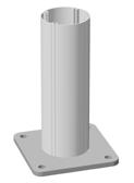
Structurally designed to support signs of up to 40m2, Optimast is constructed using recyclable aluminium and offers pole dimensions of 127mm, 168mm, 219mm and 244mm, suiting a large range of sign sizes.
Optimast is designed so that the pole breaks away at the shear bolt when impacted by a vehicle, leaving the baseplate, foundation bolts and anchor cradle intact. The anchor cradle and concrete foundation should remain undamaged and the baseplate can be easily removed – thus a new mast can be installed onto the existing anchor cradle foundation.


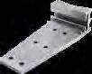
127 POLES & BASE PLATE
OPTIMAST SIGN POLES)
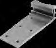
168 POLES & BASE PLATE
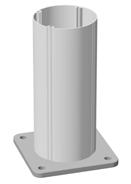
219 POLES & BASE PLATE CODE
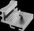
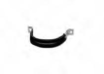
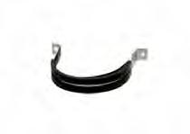
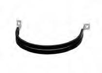
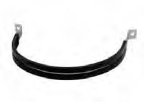
HEAVY DUTY 2-BOLT ‘D’ BRACKETS (FOR OPTIMAST SIGN POLES)
244 POLES & BASE PLATE CODE
HEAVY DUTY 2-BOLT ‘D’ BRACKETS (FOR OPTIMAST SIGN POLES)
127 ANCHOR CRADLE
SOCKETS
219 ANCHOR
SOCKETS
Sign installation must take place immediately after the mast has been installed.
The Optimast heavy duty 2-bolt D brackets with rubber insert, M8 x 50T bolt and nut must be used when attaching the sign. When the sign is mounted in the current position, the fixings are to be tightened to the correct torque settings of 18 Nm.
We advise threads to be lubricated with Rocal anti-seize stainless lubricant or similar.
1.1 Excavate the hole
For multi-pole installations, start with the pole closest to the curb.
Foundations should be excavated to a minimum diameter of 400mm1 and a depth equal to the ground sleeve length.
Remove all loose debris from the footing before pouring concrete.
1.2 Pour concrete
Concrete must be a minimum strength of 28Mpa.
Pour 100mm of concrete into the footing then bed the sleeve base into the centre of the footing, ensuring the embedment depth line is at ground level. The top of the sleeve will be 50-90mm above ground level, depending on sleeve size.
The trilobular lock ing bolts must face the oncoming traffic.
Ensuring the sleeve remains perpendicular and centred with a spirit level, pour concrete around the sleeve to the embedment depth line.
The ground sleeve may float vertically up during this concrete pour. To prevent this, maintain downward pressure on the sleeve to ensure the correct position is maintained above ground.
Once the kerbside sleeve is in place, repeat the process with the remaining sleeves.
Once all the sleeves are installed, cover and leave concrete to cure for 24 hours.
2.1 Pole insertion
Line up the flute patterns of both the ground sleeve seal and aluminium pole, then push the ground sleeve seal approximately 10mm over the base of the aluminium pole (the end closest to the pre-cut post restraint bolt holes).
Align the seal flange with the lock ing bolts, then slide the pole into the ground sleeve. The ground sleeve seal will slide up the pole into the correct position once the pole reaches the base of the ground sleeve.
Ensure the restraint holes in the ground sleeve line up with the corresponding post restraint bolt holes in pole.
The correct placement will also result in the pole shear holes aligned to the post restraint holes in the sleeve.
2.2 Transition shoe inser tion
Insert the transition shoe by lifting the aluminium pole 100m out of the ground sleeve and insert the transition shoe so that the lip is sitting flush with the top of the ground sleeve and on top of the locking bolts.
Lower the aluminium pole back into the ground sleeve, lining up the centre groove in the transition shoe with a flute in the aluminium pole.
This will ensure the transition shoe is a snug fit between the ground sleeve and aluminium pole.
2.3 Retention bolt assembly installation
Place a nylon washer onto the M12 stainless steel bolt head and insert the bolt through the hole to the other side of the ground sleeve.
Locating the thread end of the bolt, fit a nylon washer & kinmar lock nut onto the thread and tighten to 10-12 Nm torque with the kinmar socket.
2. ALUMINIUM POLE INSTALLATION (cont.)
2.4 Fasten transition shoe & insert shear hole bung plugs
Using the trilobular spanner or trilobular key, tighten the sleeve locking bolts to 10-12 Nm torque.
Push both bung plugs into the pre-cut shear holes located on each side of the fluted aluminium pole and just above the ground sleeve seal.
3. INSTALL THE SIGN ONTO ALUMINIUM POLE ASSEMBLIES
Cut aluminium poles to required size.
Fit poly caps to aluminium poles

NB. Drawings are not to scale, and used for illustrative purposes only.
1.1 Excavate the trench
Using suitable equipment, excavate the trench to the dimensions specified by the independent scheme designer.
1.2 Secure anchor cradles
The anchor cradle must be securely suspended in the foundation in its final position.
Level and align prior to concreting the foundation. This is usually achieved by nailing or screwing the template board to timbers spanning across the excavation or the foundation shuttering.
The underside of the removable template board is to be set to the top of concrete level. The template board should be checked with a spirit level to ensure it is level and the arrangement checked to ensure it is robust and rigid before concreting.
1.3 Pour concrete
Anchorages and baseplates of the masts should be exposed and not buried under soil. The top of the concrete foundation should be level or not more than 50mm above the surrounding ground or paving to prevent the underside of errant vehicles catching on the concrete before hitting the sign mast in a vehicle impact. The concrete must be mechanically vibrated to ensure that all air pockets and voids are eliminated from the foundation concrete.
Signfix recommends minimum concrete grade of 28MPa. However, the final design is the responsibility of the scheme designer.
Immediately after concreting the bolt position the alignment should be re-checked to ensure the anchor cradles have not moved.
The template boards may be removed the day after concreting but the temporary/disposable bolts should be retained to protect the anchor socket threads until the sign mast can be erected.
Masts and sign plates should not be erected until the contractor is satisfied the concrete has reached a cube strength of 28MPa. To erect masts earlier after concreting, stronger concrete can be used to shorten the time needed to achieve the 28MPa cube strength.
2.1 Inser t foundation studs into anchor cradle socket
Remove any debris from around the anchor and check the concrete for high spots that may prevent the mast from seating correctly on the bolts.
Remove and dispose of the temporary/disposable bolts and the template board.
Grease anchor studs and the internal threads of the anchorage sockets threads with Rocol anti-seize stainless lubricant or similar.
Screw the 4 studs by hand into the anchor socket as per the table below.
Bolt insertion depths:
Mast Type Stud DiameterLength in socket
127M16 32mm
168M20 40mm
219M20 40mm
244M24 48mm
Maximum height of exposed thread:
Mast Type Stud DiameterExposed thread length
127M16 104mm
168M20 116mm
219M20 116mm
244M24 137mm
2.2 Fitting the Optimast
Length in socket
Screw one stainless steel nut down each stud until they lock tight onto each socket in the concrete. Tighten each nut with a spanner but do not apply excess torque, this will prevent the stud from turning during subsequent operations.
Screw a second stainless nut down onto each stud until they are all approximately 3 mm above the first nut. Check across all four second stainless nuts with a spirit level and adjust by screwing up or down until all four nuts are precisely level to create a level bed for the mast base plate.
Apply to each stud a stainless-steel washer.
Lower the mast onto the studs, taking care not to damage the threads.
Exposed thread length
2. ERECTION OF THE OPTIMAST ONTO THE ANCHOR CRADLES (cont.)
2.3 Securing the Optimast
Apply a stainless-steel washer to each stud, then a third stainless steel nut and hand-tighten. Check the base plate is fully seated on all four studs and the mast is vertical. If not, slacken off third stainless steel nut and adjust the nuts under the baseplate. Hand-tighten the nuts on top again and re-check.
When you are satisfied that the mast is vertical and fully seated, tighten the third stainless steel nut to the recommended torque using a torque wrench. See below table for torque settings.
The nuts below the baseplate should be checked to ensure they do not rotate and if necessary, an open ended spanner should be used to prevent any rotation.
Apply a fourth stainless steel nut to each stud and tighten to the torque recommended using a torque wrench. See below table for torque settings.
Screw the first stainless steel nut touching the concrete/socket up against the second stainless steel nut under the base plate and firmly tighten with an open ended spanner.
Re -check the mast is vertical using a suitable measuring device.
MASH FRANGIBLE SIGN SUPPORT INSTALLATION | WIND CHARTS
ZEALAND WIND
NZ1.1 (<10M2
NZ1.2 (<28M2
NZ1.3 (<40M2 SIGNS)
NZ2.1 (<10M2 SIGNS)
NZ2.2 (<28M2 SIGNS)
NZ2.3 (<40M2
NZ3.1 (<10M2 SIGNS)
NZ3.2 (<28M2 SIGNS)
Optimast, Range: 1028, Wind Region NZ 1, TC 2, BtoC Ratio: 4.98, 5 POSTS
ON UNEVEN GROUND H = HEIGHT OF THE TALLEST POST. CHARTS ARE BASED ON EXPOSED LOCATIONS SUCH AS OPEN GRASSLAND, ISOLATED TREES (AS1170.2 TERRAIN CATEGORY 2) AND DESIGNED FOR IMPORTANCE LEVEL 2. DESIGN LIFE IS 25 YEARS. CHARTS ASSUME THAT DIMENSION 'A' IS NO MORE THAN FIVE (5) TIMES DIMENSION "B". IF A IS GREATER THAN 5xB CONTACT SUPPLIER FOR DESIGN ADVICE. WHERE SIGNAGE ASSEMBLIES ARE TO COMPLY WITH THE APPROVED TECHNICAL CONDITIONS OF USE FOR FRANGIBILITY, THE SIGN GEOMETRY IS TO COMPLY WITH THE FOLLOWING MINIMUM POST HEIGHTS (H+B): OPTIMAST 127 = 2.4m, OPTIMAST 168/OPTIMAST 219/OPTIMAST 244 = 4.6m SINGLE POST SIGN SUPPORTS MUST ONLY BE USED WHERE THE SIGN ATTACHMENT RESISTS ROTATION AND IS IN ACCORDANCE WITH STATE AUTHORITY GUIDELINES. REFER TO THE OPTIMAST PRODUCT MANUAL FOR ADDITIONAL TECHNICAL INFORMATION.
1. 2. 3. 4. 5. 6.
Optimast, Range: 1028, Wind Region NZ 2, TC 2, BtoC Ratio: 4.98, 5 POSTS
ON UNEVEN GROUND H = HEIGHT OF THE TALLEST POST. CHARTS ARE BASED ON EXPOSED LOCATIONS SUCH AS OPEN GRASSLAND, ISOLATED TREES (AS1170.2 TERRAIN CATEGORY 2) AND DESIGNED FOR IMPORTANCE LEVEL 2. DESIGN LIFE IS 25 YEARS. CHARTS ASSUME THAT DIMENSION 'A' IS NO MORE THAN FIVE (5) TIMES DIMENSION "B". IF A IS GREATER THAN 5xB CONTACT SUPPLIER FOR DESIGN ADVICE. WHERE SIGNAGE ASSEMBLIES ARE TO COMPLY WITH THE APPROVED TECHNICAL CONDITIONS OF USE FOR FRANGIBILITY, THE SIGN GEOMETRY IS TO COMPLY WITH THE FOLLOWING MINIMUM POST HEIGHTS (H+B): OPTIMAST 127 = 2.4m, OPTIMAST 168/OPTIMAST 219/OPTIMAST 244 = 4.6m SINGLE POST SIGN SUPPORTS MUST ONLY BE USED WHERE THE SIGN ATTACHMENT RESISTS ROTATION AND IS IN ACCORDANCE WITH STATE AUTHORITY GUIDELINES. REFER TO THE OPTIMAST PRODUCT MANUAL FOR ADDITIONAL TECHNICAL INFORMATION.
1. 2. 3. 4. 5. 6.
Range: 010, Wind Region NZ 3, TC 2, BtoC Ratio: 4.98, 5 POSTS
Optimast, Range: 010, Wind Region NZ 3, TC 2, BtoC Ratio: 4.98, 5 POSTS
ON UNEVEN GROUND H = HEIGHT OF THE TALLEST POST. CHARTS ARE BASED ON EXPOSED LOCATIONS SUCH AS OPEN GRASSLAND, ISOLATED TREES (AS1170.2 TERRAIN CATEGORY 2) AND DESIGNED FOR IMPORTANCE LEVEL 2. DESIGN LIFE IS 25 YEARS. CHARTS ASSUME THAT DIMENSION 'A' IS NO MORE THAN FIVE (5) TIMES DIMENSION "B". IF A IS GREATER THAN 5xB CONTACT SUPPLIER FOR DESIGN ADVICE. WHERE SIGNAGE ASSEMBLIES ARE TO COMPLY WITH THE APPROVED TECHNICAL CONDITIONS OF USE FOR FRANGIBILITY, THE SIGN GEOMETRY IS TO COMPLY WITH THE FOLLOWING MINIMUM POST HEIGHTS (H+B): OPTIMAST 127 = 2.4m, OPTIMAST 168/OPTIMAST 219/OPTIMAST 244 = 4.6m SINGLE POST SIGN SUPPORTS MUST ONLY BE USED WHERE THE SIGN ATTACHMENT RESISTS ROTATION AND IS IN ACCORDANCE WITH STATE AUTHORITY GUIDELINES. REFER TO THE OPTIMAST PRODUCT MANUAL FOR ADDITIONAL TECHNICAL INFORMATION.
1. 2. 3. 4. 5. 6. NOTES
Optimast, Range: 1028, Wind Region NZ 3, TC 2, BtoC Ratio: 4.98, 5 POSTS
Optimast, Range: 2840, Wind Region NZ 3, TC 2, BtoC
ON UNEVEN GROUND H = HEIGHT OF THE TALLEST POST. CHARTS ARE BASED ON EXPOSED LOCATIONS SUCH AS OPEN GRASSLAND, ISOLATED TREES (AS1170.2 TERRAIN CATEGORY 2) AND DESIGNED FOR IMPORTANCE LEVEL 2. DESIGN LIFE IS 25 YEARS. CHARTS ASSUME THAT DIMENSION 'A' IS NO MORE THAN FIVE (5) TIMES DIMENSION "B". IF A IS GREATER THAN 5xB CONTACT SUPPLIER FOR DESIGN ADVICE. WHERE SIGNAGE ASSEMBLIES ARE TO COMPLY WITH THE APPROVED TECHNICAL CONDITIONS OF USE FOR FRANGIBILITY, THE SIGN GEOMETRY IS TO COMPLY WITH THE FOLLOWING MINIMUM POST HEIGHTS (H+B): OPTIMAST 127 = 2.4m,
Optimast, Range: 010, Wind Region NZ 4, TC 2, BtoC Ratio: 4.98, 5 POSTS
AREA (A
Optimast, Range: 010, Wind Region NZ 4, TC 2, BtoC Ratio: 4.98, 5 POSTS
1. 2. 3. 4. 5. 6. NOTES H' (mm) = H + B/2
ON UNEVEN GROUND H = HEIGHT OF THE TALLEST POST. CHARTS ARE BASED ON EXPOSED LOCATIONS SUCH AS OPEN GRASSLAND, ISOLATED TREES (AS1170.2 TERRAIN CATEGORY 2) AND DESIGNED FOR IMPORTANCE LEVEL 2. DESIGN LIFE IS 25 YEARS. CHARTS ASSUME THAT DIMENSION 'A' IS NO MORE THAN FIVE (5) TIMES DIMENSION "B". IF A IS GREATER THAN 5xB CONTACT SUPPLIER FOR DESIGN ADVICE. WHERE SIGNAGE ASSEMBLIES ARE TO COMPLY WITH THE APPROVED TECHNICAL CONDITIONS OF USE FOR FRANGIBILITY, THE SIGN GEOMETRY IS TO COMPLY WITH THE FOLLOWING MINIMUM POST HEIGHTS (H+B): OPTIMAST 127 = 2.4m, OPTIMAST 168/OPTIMAST 219/OPTIMAST 244 = 4.6m SINGLE POST SIGN SUPPORTS MUST ONLY BE USED WHERE THE SIGN ATTACHMENT RESISTS ROTATION AND IS IN ACCORDANCE WITH STATE AUTHORITY GUIDELINES. REFER TO THE OPTIMAST PRODUCT MANUAL FOR ADDITIONAL TECHNICAL INFORMATION.
Optimast, Range: 1028, Wind Region NZ 4, TC 2, BtoC Ratio: 4.98, 5 POSTS

STRUCTURAL DRAWINGS ARE TO BE READ IN CONJUNCTION WITH ALL CLIENT
SPECIFICATIONS AND THE SIGNFIX/OPTIMAST PRODUCT MANUAL. SIGNS TO BE ACCORDANCE WITH NZTA P24:2020 -SPECIFICATION FOR PERMANENT TRAFFIC SIGNS ALL MATERIALS AND WORKMANSHIP SHALL BE IN ACCORDANCE WITH THE LATEST VERSIONS OF THE FOLLOWING STANDARDS EXCEPT WHERE VARIED BY THE SPECIFICATION AND / OR DRAWINGS: AS.2159 PILING -DESIGN AND INSTALLATION NZS.3101 CONCRETE STRUCTURES STANDARD NZS.3109 CONCRETE CONSTRUCTION AS/NZS.1664ALUMINIUM CODE AS/NZS.1866ALUMINIUM AND ALUMINIUM ALLOYS
DIMENSIONS NOT TO BE SCALED. SET OUT DIMENSIONS ARE TO BE VERIFIED WITH CLIENT SPECIFICATIONS.
SIGNFIX/OPTIMAST PRODUCTS HAVE BEEN CHECKED FOR WIND LOAD CAPACITY ONLY. REFER MANUFACTURER FOR FRANGIBILITY PERFORMANCE.
THE CONTRACTOR SHALL BE RESPONSIBLE FOR MAINTAINING STABILITY OF THE STRUCTURE UNTIL COMPLETION OF CONSTRUCTION AND SHALL ENSURE THAT NO PART OF THE STRUCTURE IS OVER STRESSED BY EXCESSIVE CONSTRUCTION LOADING.
SIGN POSTS TO BE SIZED IN ACCORDANCE WITH MANUFACTURER DESIGN INFORMATION
BASED ON SIGNAGE AREAS, HEIGHTS AND WIND ENVIRONMENT. DRAWING IS TO BE USED TO DETAIL FOUNDATION REQUIREMENTS CORRESPONDING TO NOMINATED POST SIZE.
ADDITIONAL ATTACHMENTS ARE NOT PERMITTED ON SIGNFIX MASH SIGN SUPPORT OR ON
OPTIMAST MASH SIGN SUPPORT.
ADDITIONAL ATTACHMENTS INCLUDE BUT NOT LIMITED TO THE FOLLOWING:SOLAR PANEL, CAMERA, BATTERY, ANYTHING OTHER THAN A STATIC SIGN.
DRAWING VALID FOR SIGNS WITH H' GREATER THAN 2.1m
FOUNDATIONS
FOUNDATION EXCAVATIONS TO BE MAINTAINED IN A FIRM DRY CONDITION. REMOVE ANY
SOFT GROUND AND FILL WITH MASS CONCRETE.
FOOTING SIZES ARE BASED ON GEOTECHNICAL PARAMETERS AS FOLLOWS:
STRENGTH CATEGORY
UNDRAINED
INDENTED BY STRONG FINGER PRESSURE AND CAN BE INDENTED BY THUMB PRESSURE COHESIVE CLAY SOILS
SOFT TO FIRMFIRM TO STIFFSTIFF TO VERY STIFF/HARD VERY STIFF/HARD
SHEAR STRENGTH Cu (kPA) 25 50 100 200 FIELD IDENTIFICATION
CANNOT BE INDENTED BY THUMB PRESSURE
STRENGTH
CATEGORY
FRICTION ANGLE (DEGREES) FIELD IDENTIFICATION
NOTE:
CAN BE INDENTED BY THUMB NAIL
DIFFICULT TO INDENT BY THUMB NAIL
COHESIONLESS SAND SOILS
LOOSE TO MEDIUM DENSE MEDIUM DENSE TO DENSE DENSE TO VERY DENSE VERY DENSE 27 30 35 38 SOIL TYPE SHOULD BE ASSESSED FROM APPROPRIATE INVESTIGATION
POOR GROUND WITH A Cu LESS THAN 25kPa IS NOT RECOMMENDED FOUNDATION FOR ROAD SIGNAGE. THESE VALUES ARE A GUIDE ONLY, SOIL CONDITIONS FOR EACH FOOTING ARE TO BE ASSESSED BY SUITABLY QUALIFIED PERSONNEL.
REFER TO SIGNFIX FOR DIRECTIONS IF THE SITE CONDITIONS DO NOT CONFORM TO THE MINIMUM DESIGN REQUIREMENTS.
FOOTING DEPTH IS EMBEDMENT LENGTH INTO SOIL STRENGTH CATEGORY TABULATED.
DISREGARD LOOSE TOPSOIL AND FILL WHEN MEASURING FOOTING DEPTHS. GROUND CONDITIONS TO BE CONFIRMED ON SITE BY A SUITABLY QUALIFIED PROFESSIONAL ENGAGED BY THE MAIN CONTRACTOR.


Signfix New Zealand is a division of Delnorth International ABN 26 051 954 977.
For further information visit www.signfix.com Distributor: Fulton Hogan Signs P 0800 744 639 E sales@signfix.nz 455 Blenheim Road, Christchurch NZ 8042T