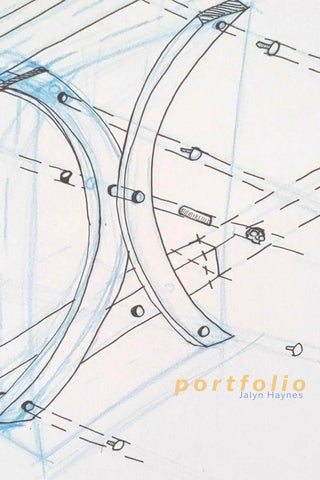
portfolio Jalyn
Haynes
Whack-A-Mole 8 Fall 2020
Ruled Pavilion 18 Fall 2020

Knitted Squares and Chains 2 Fall 2020
content

34
The Rhind 26 Fall 2021 Transparency
Fall 2022
Professor Virginia Melnyk Fall 2020
knitted squares and chains
ARCH 2510 Studio: Architecture Foundations I
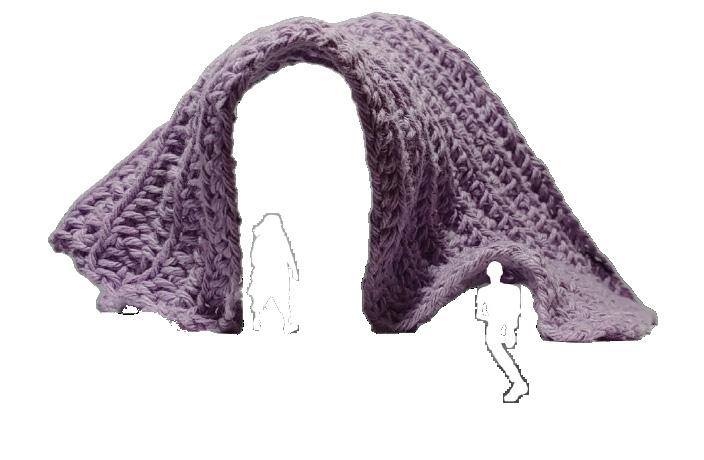
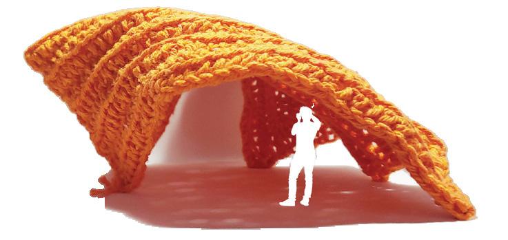
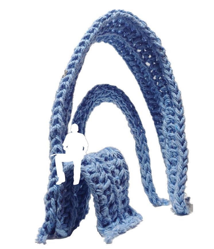
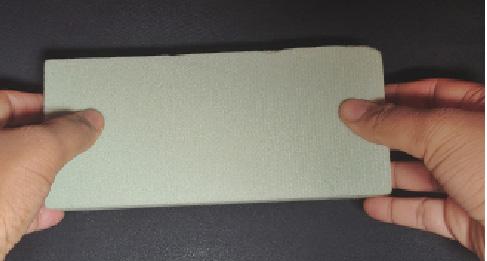
Using plaster, cloth, chains and knitted fabric,I designed pavilions applying catenary arches. This was one part of a three-part exploration of Louis Kahn’s “rigorous play”. For this process, I knitted different square and rectangular shapes, adhered them to boards at different places on a board and hung them up-side down.
2
Images : Three Knitted Study Models
This is an ongoing study on textiles, catenary curves and interaction. This exercise became increasingly important to me throughout my studies. Often when I found myself unable to think through my work, I would return to hanging as a way to think through organic shapes .


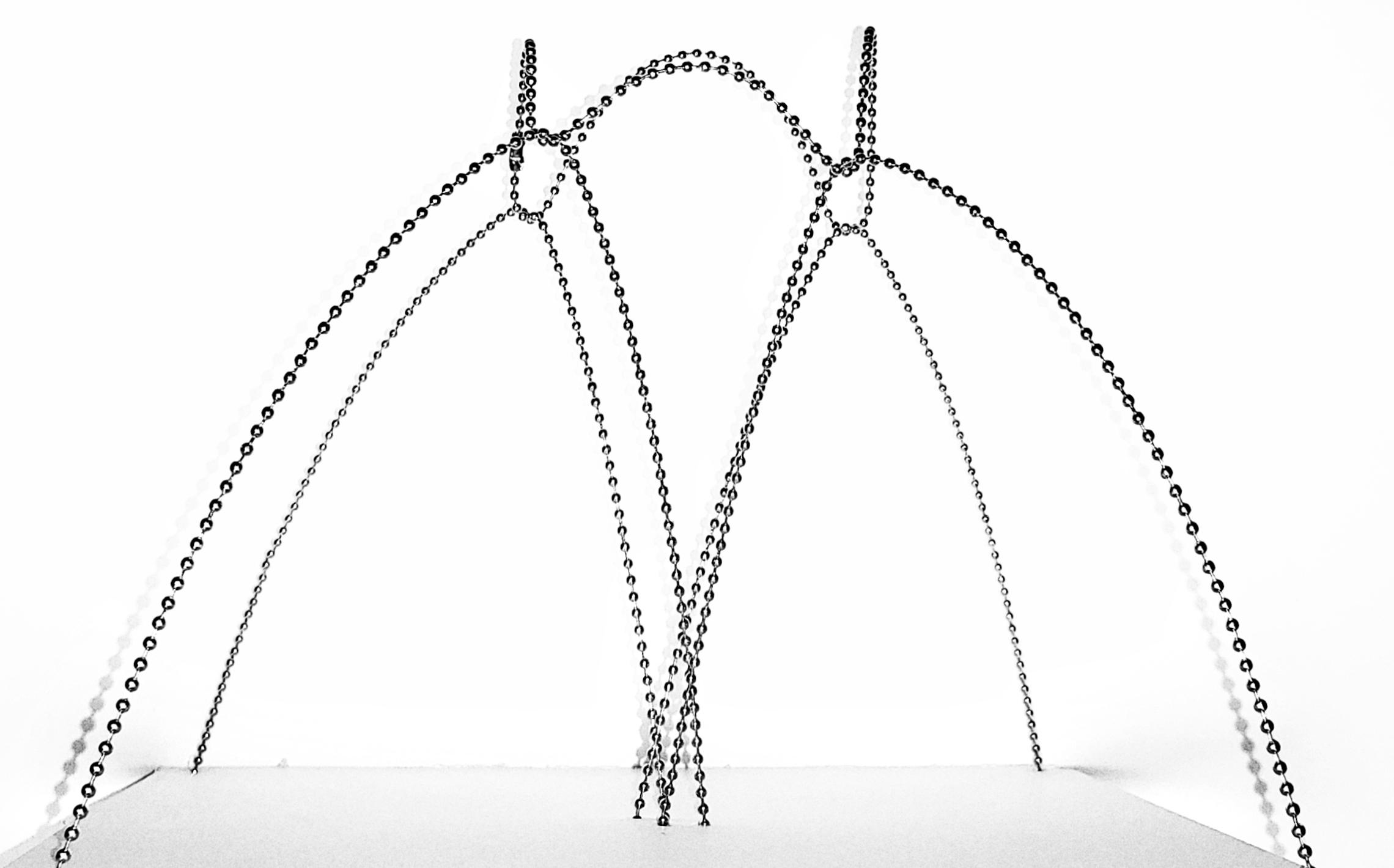
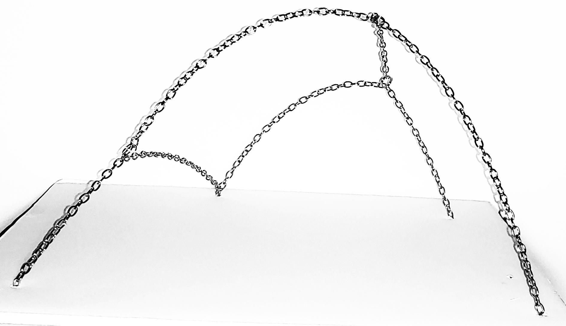
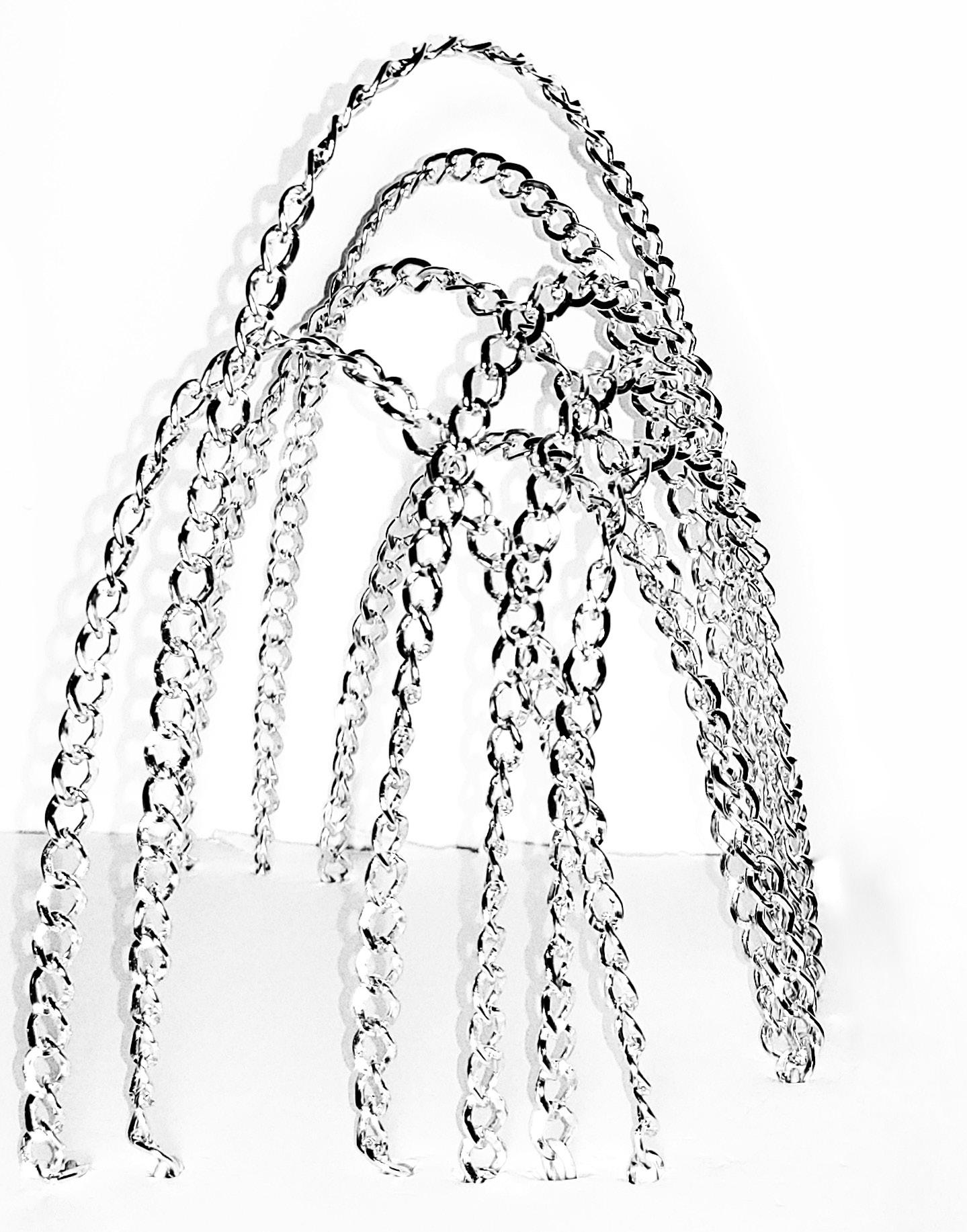

Images
Study Models 4
: Three Chain
whack-a-mole
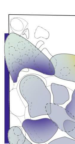
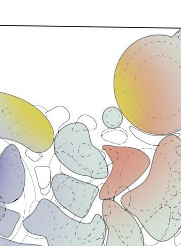
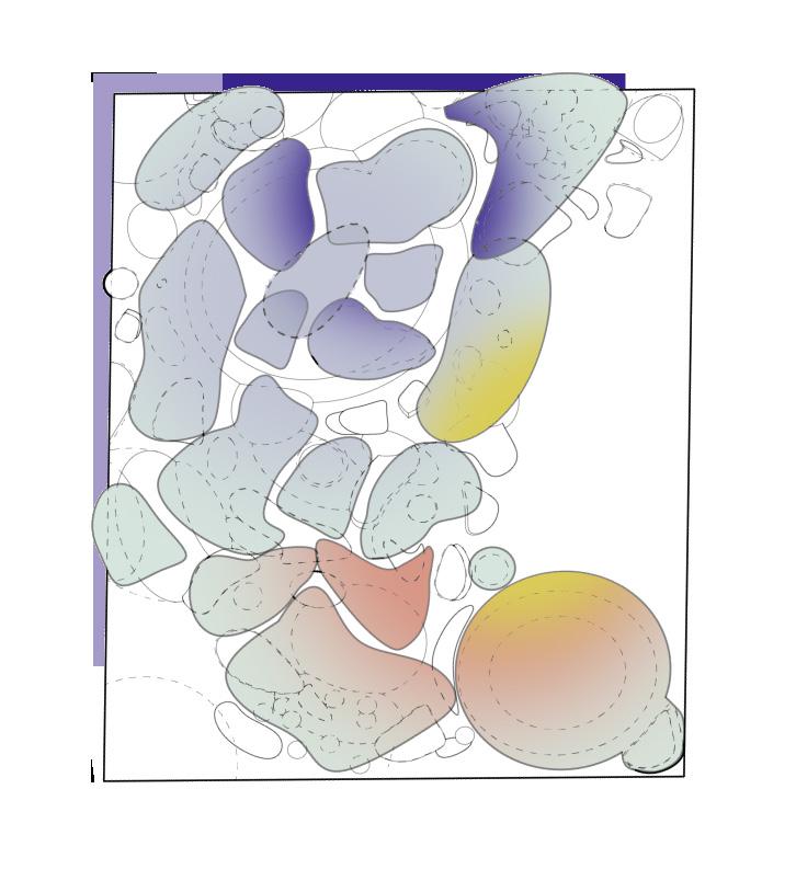
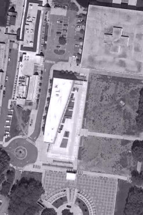
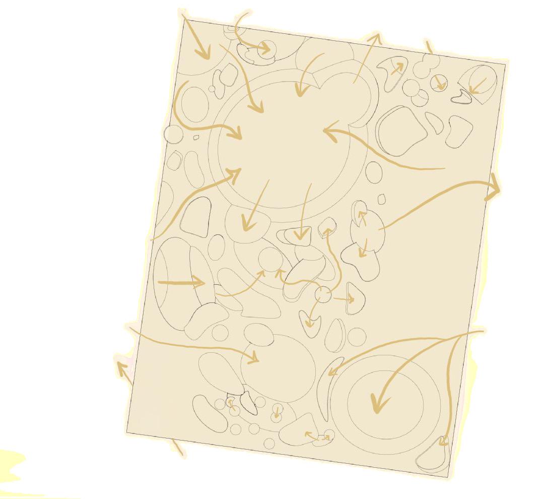
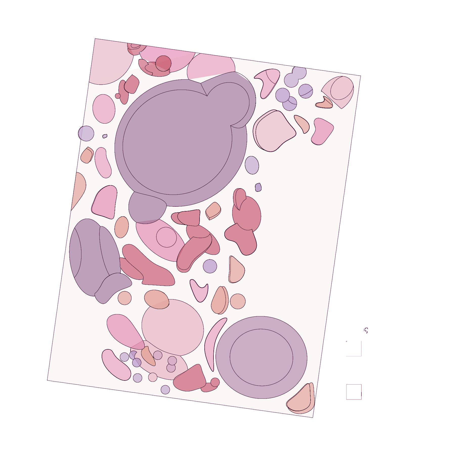
Images : Roof Plan Overlay
ARCH 1510 Studio: Architecture Foundations I Professor Virginia Melnyk Fall 2020
WHACK-A-MOLE
The first of two projects concerning the fundamental elements of architectural design laid out by our professors (folding, handing, bending and lofting), dealt with creating a grid to design the layout of an outdoor classroom on Clemson University campus.
By following COVID-19 social distancing guidelines, each area was designed for large and small classes and individual work spaces. For this project, I used what I learned in the previous handing project by using negative space, encouraging flexible circulation and practicing on moldable physical materials.
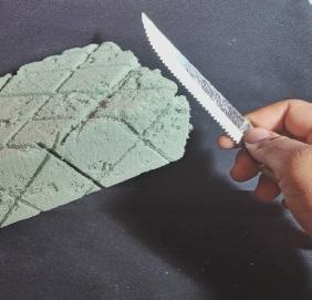
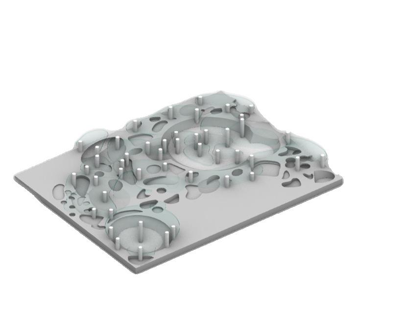
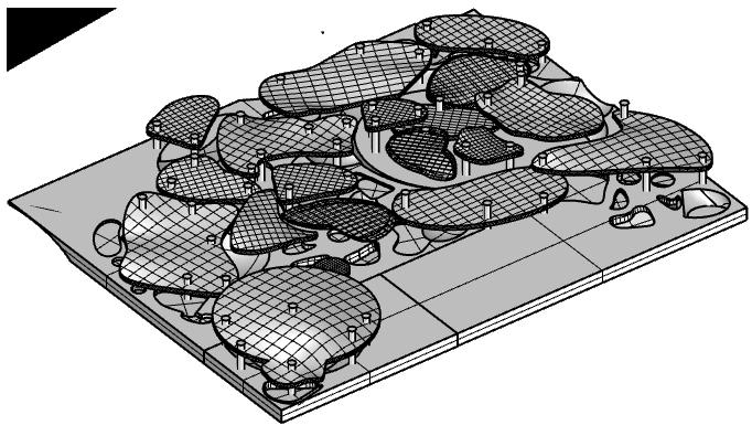
Images(LEFT TOP) : Photo of Site Plan with Roof Plan Overlay Images (LEFT BOTTOM): Three Physical Model Process Photos Image (TOP RIGHT): Circulation Diagram
Being able to creatively solve a problem was what made this project the most interesting. Physical models have always been difficult for me. By using a simple shape and carving out of it , practicing skills for physical model making was crucial . Rendering was also a skill that was taught during this semester. Though I found it difficult, I really enjoyed attempting to create the mood of the environment.
Large Outdoor Classroom Single Occupancy Study Multi-level Classrooms Double Occupancy Study Medium Occupancy Classroom
9
Images(LEFT ): Program Diagram Images (RIGHT TOP AND BOTTOM): Sections
10

Images(LEFT
12
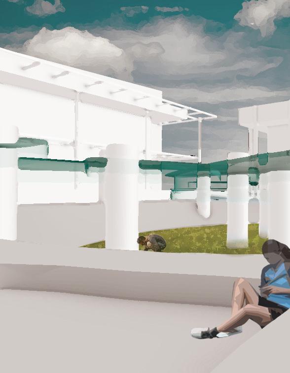
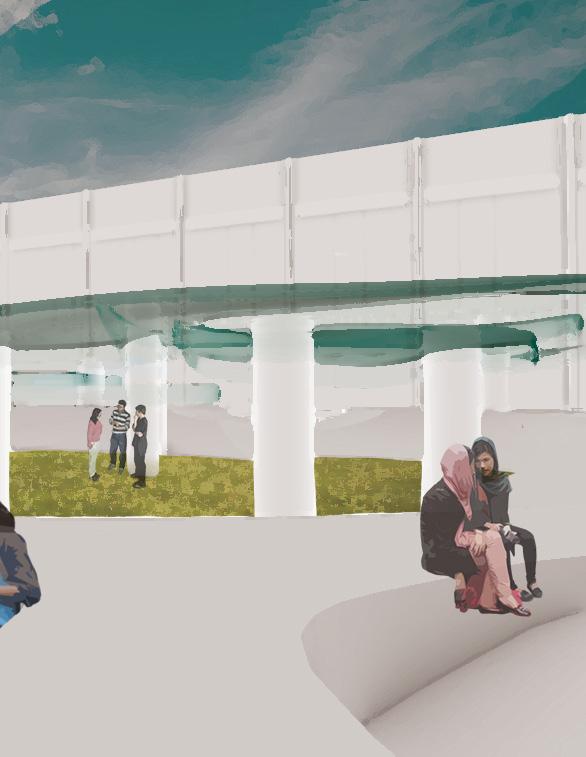
Image: Interior Rendering
): Process Diagram
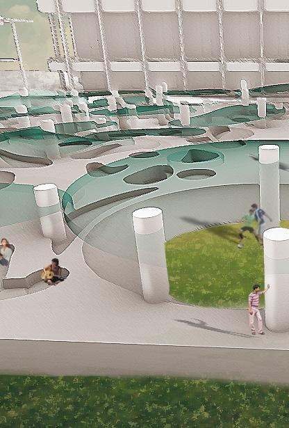
 Image: Exterior Rendering
Ruler Pavilion
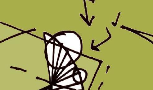
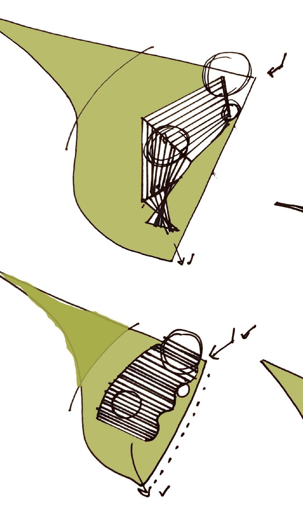
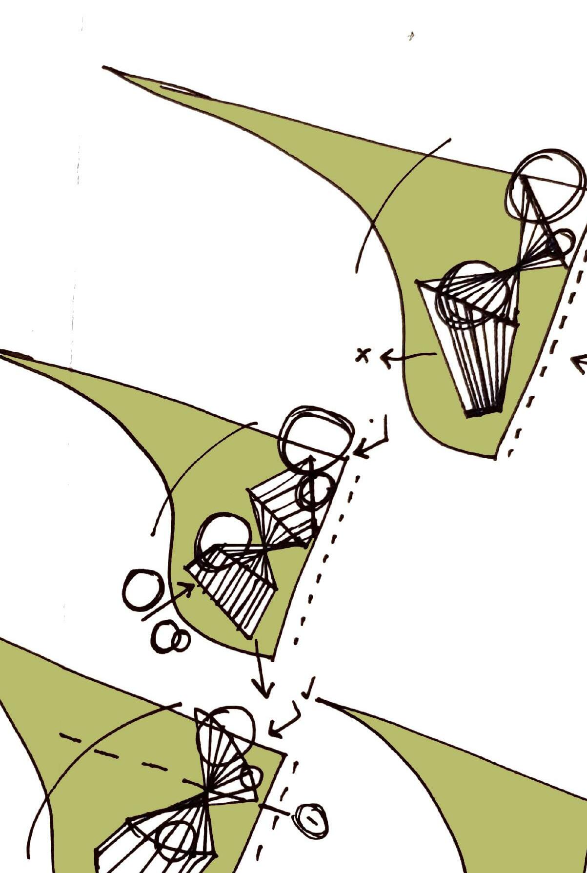
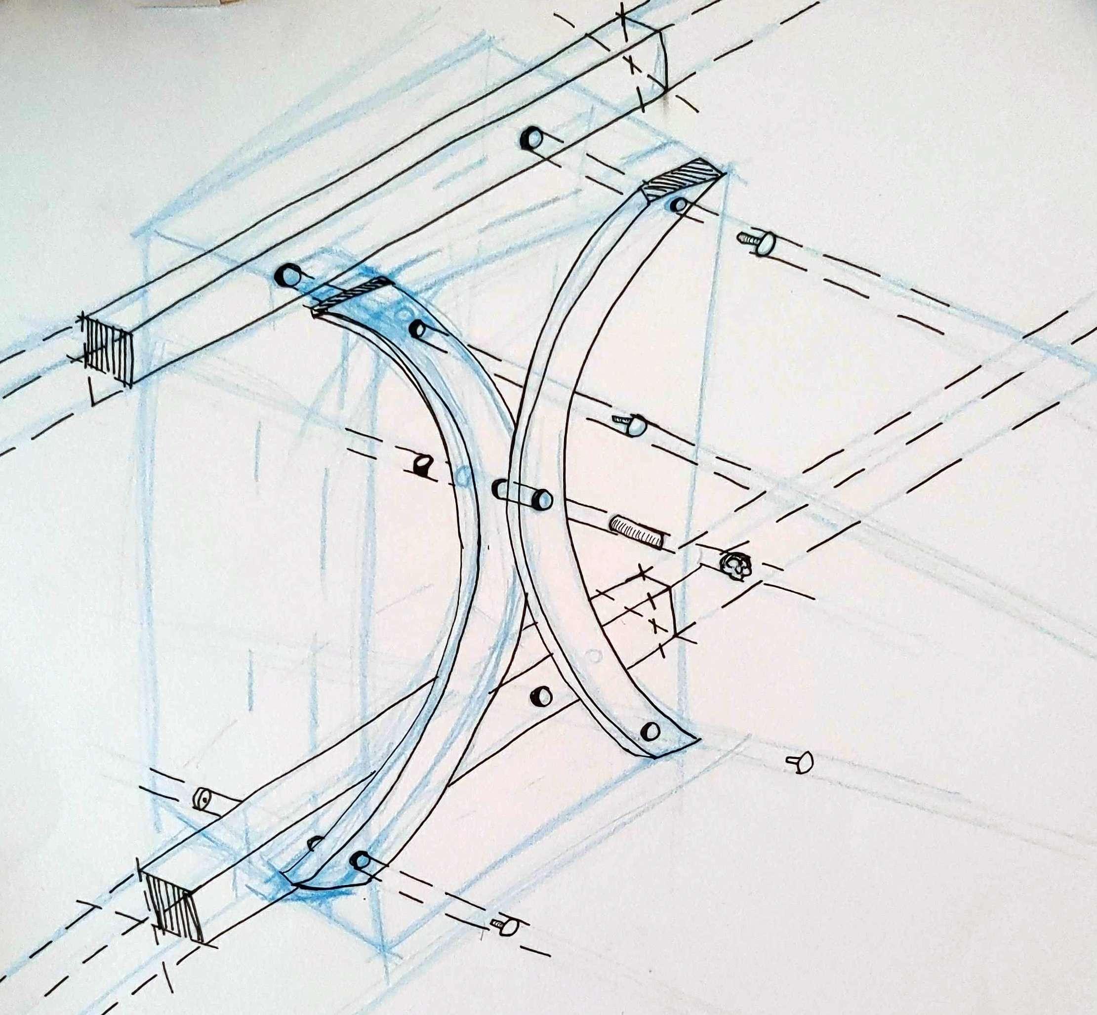
 Image: Immediate Site Planning Sketches
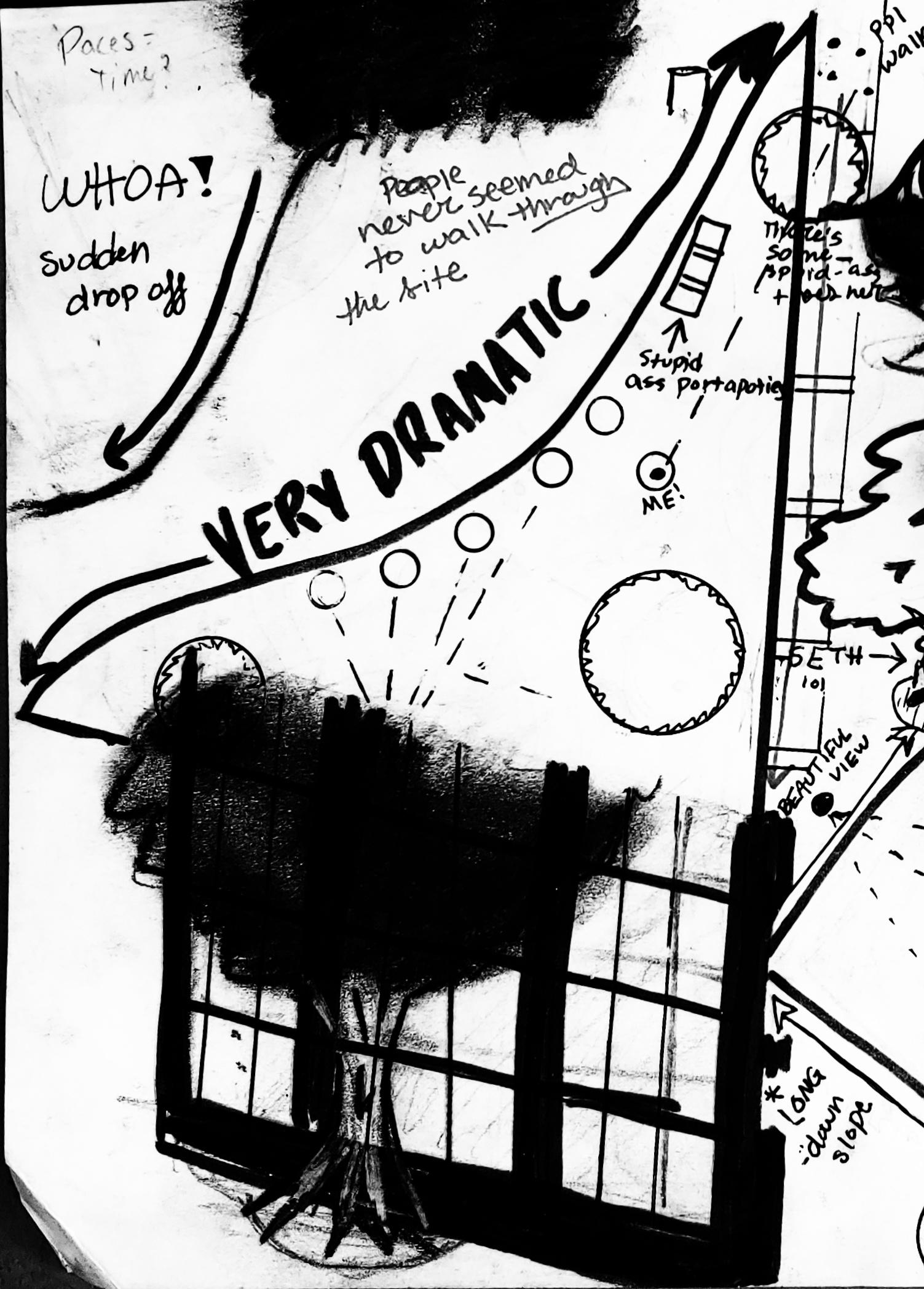
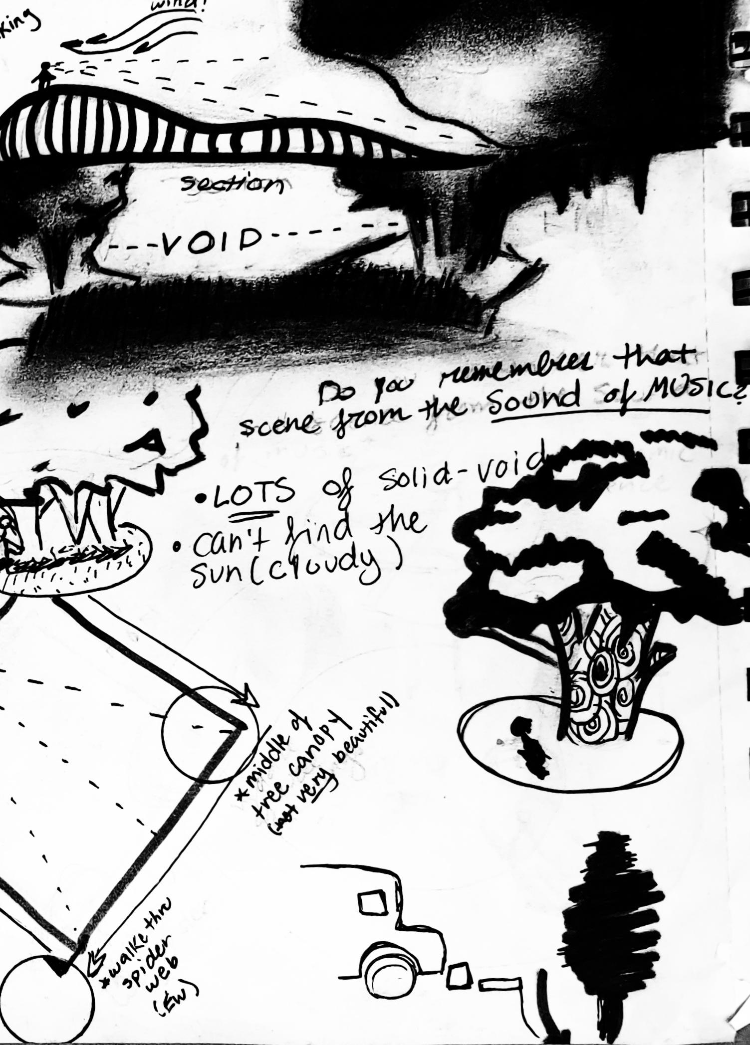
Image: Site Analysis Sketches
Ruler Pavilion
ARCH 2510 Studio: Architecture Foundations I
Professor Virginia Melnyk

Fall 2020

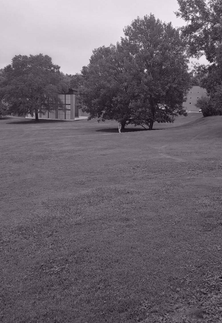
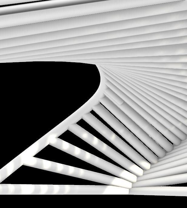
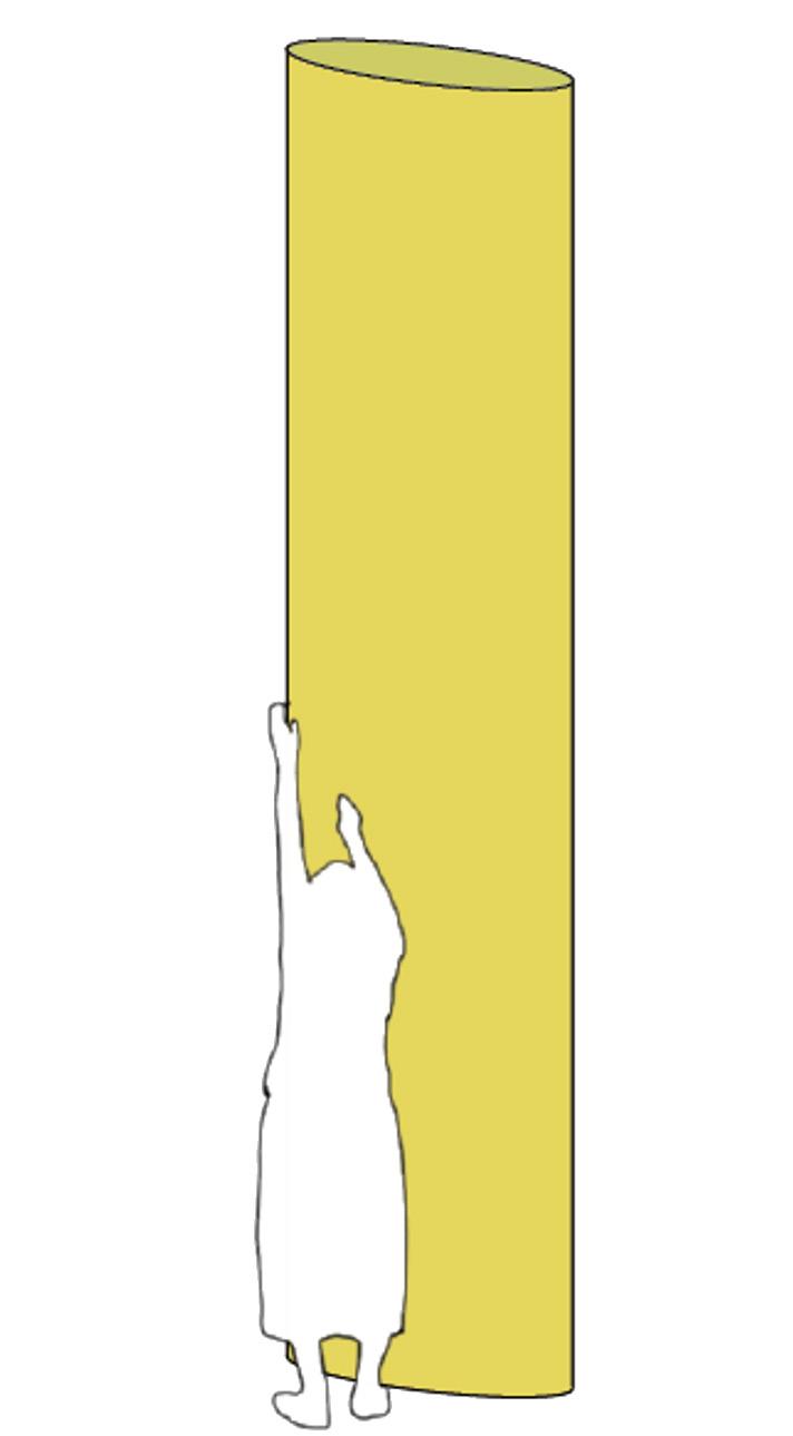
For the second of two projects concerning the fundamental elements of architectural design laid out by our professors (folding, handing, bending and lofting) we were tasked with designing an outdoor pavilion on Clemson University Campus. I choose to loft three curves , by using piece of white Polyvinyl Chloride, or PVC, pipes.
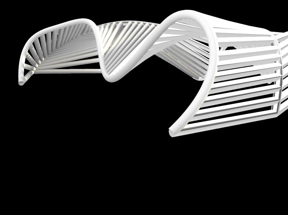
Image (LEFT): Site Photo with Exterior Rendering Overlay
19


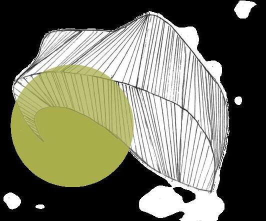
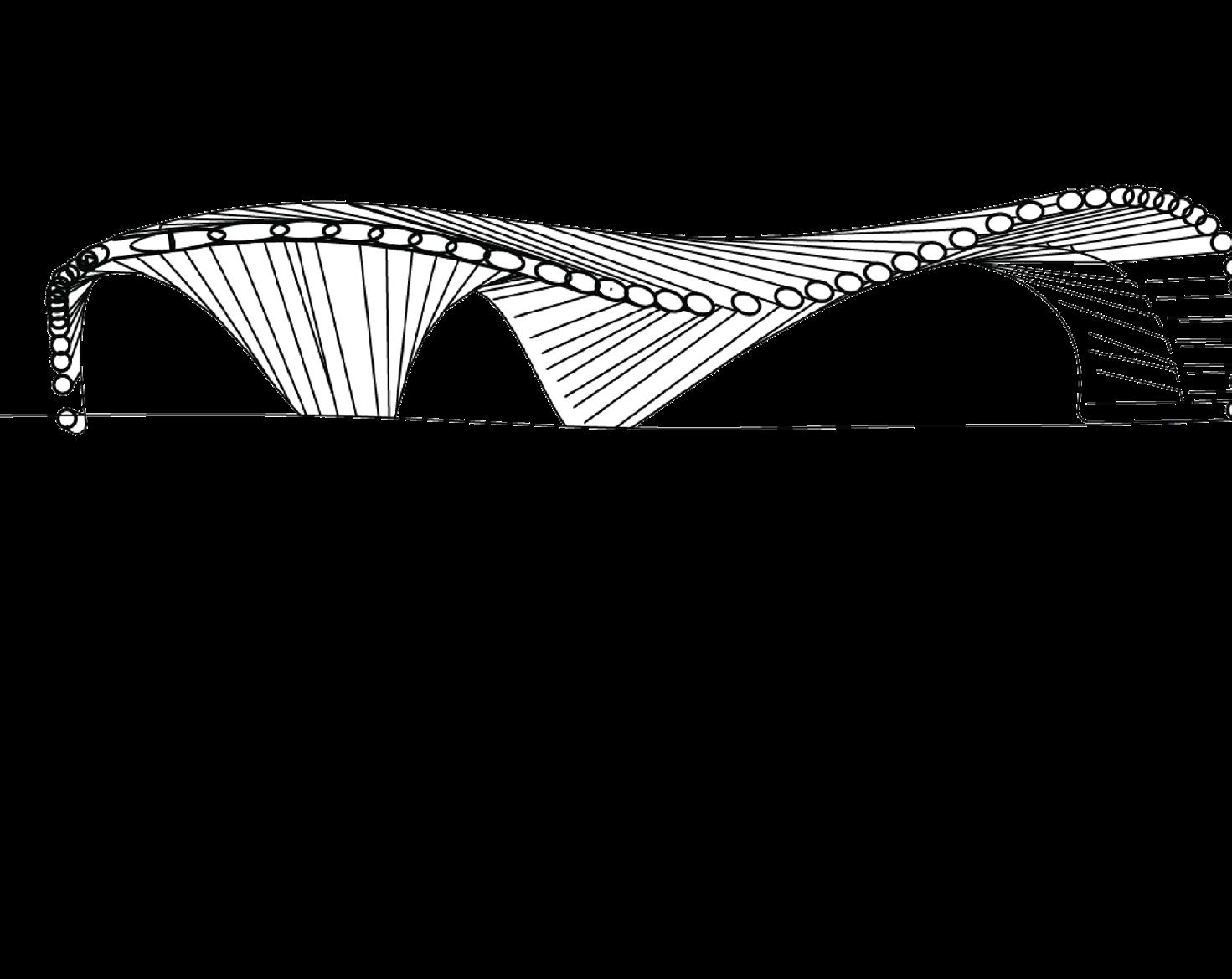

 Image (TOP RIGHT): Section Perspective Image BOTTOM RIGHT): Site Plan with Parti Overlay
21
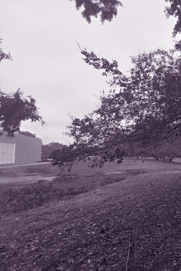
The uncolored pipe would be used to highlight the environment around and imitate the exposed structure of Clemson’s Arts, Architecture and Humanities building, Lee Hall . The Ruler Pavilion was an exercise on understanding human proportions and interaction with the surrounding environment . During this project, I became very dependent on my sketchbook and found sketching a vital part in my design process.
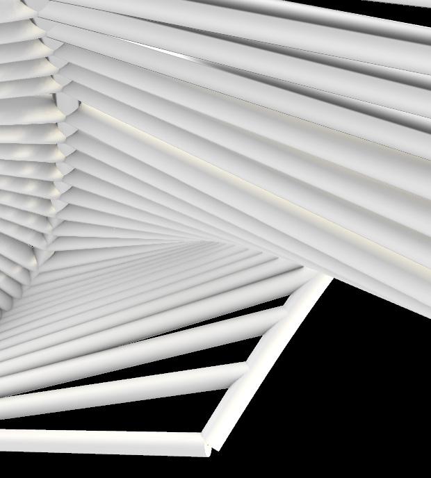
 Image (LEFT): Site Photo with Interior Rendering Overlay
the rhind
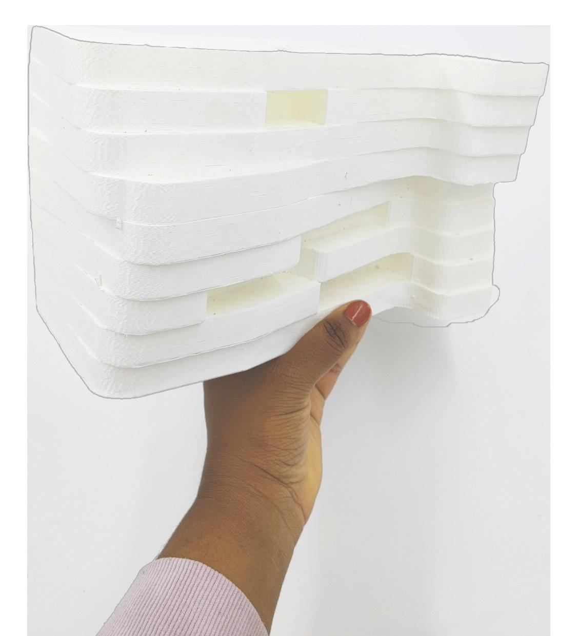
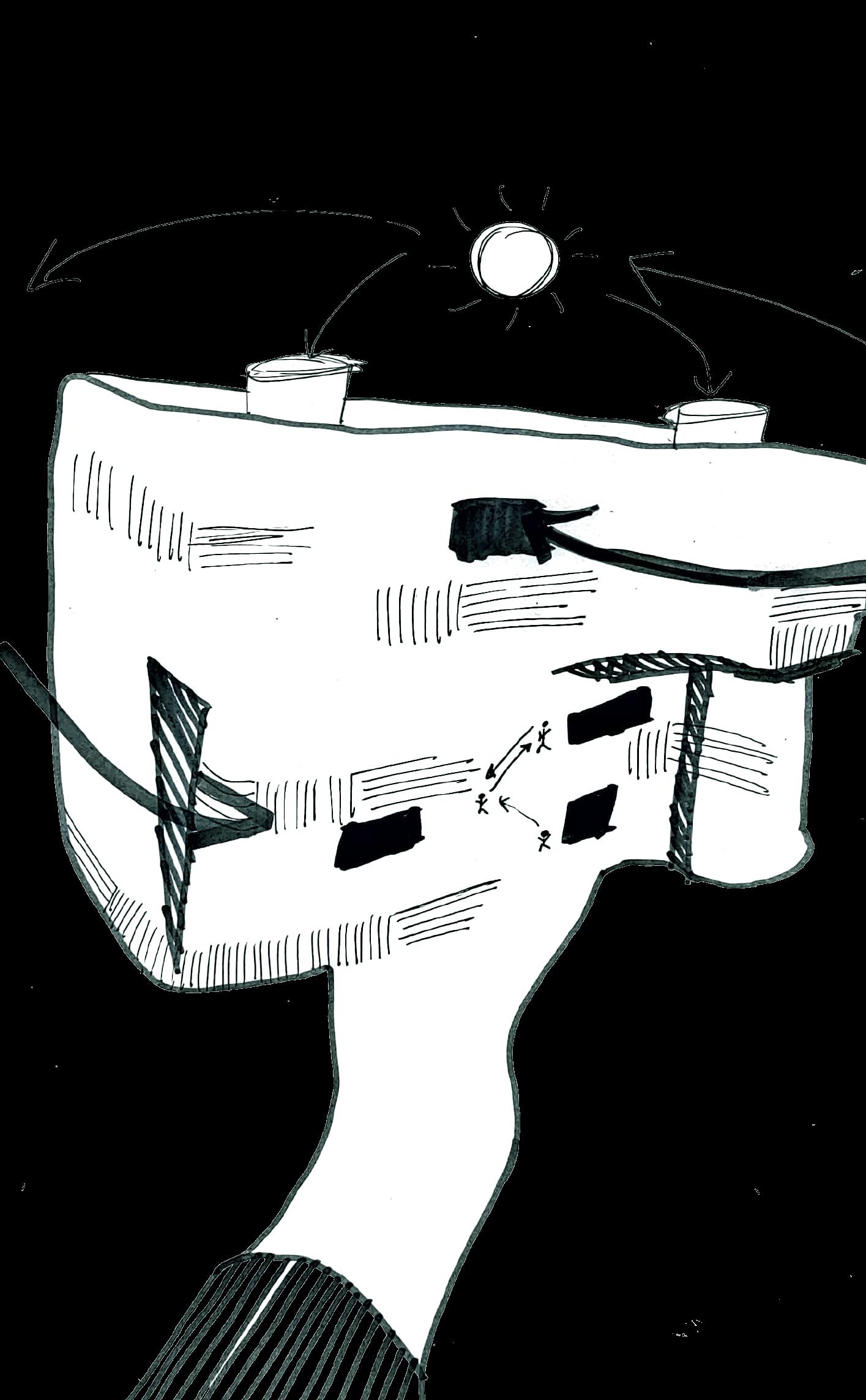
Image: 3D Print with Planning Sketches Overlay
ARCH 3050 Studio: Urban Context Professor Douglas Hecker
Fall 2021 In collaboration with Amber Choice
25
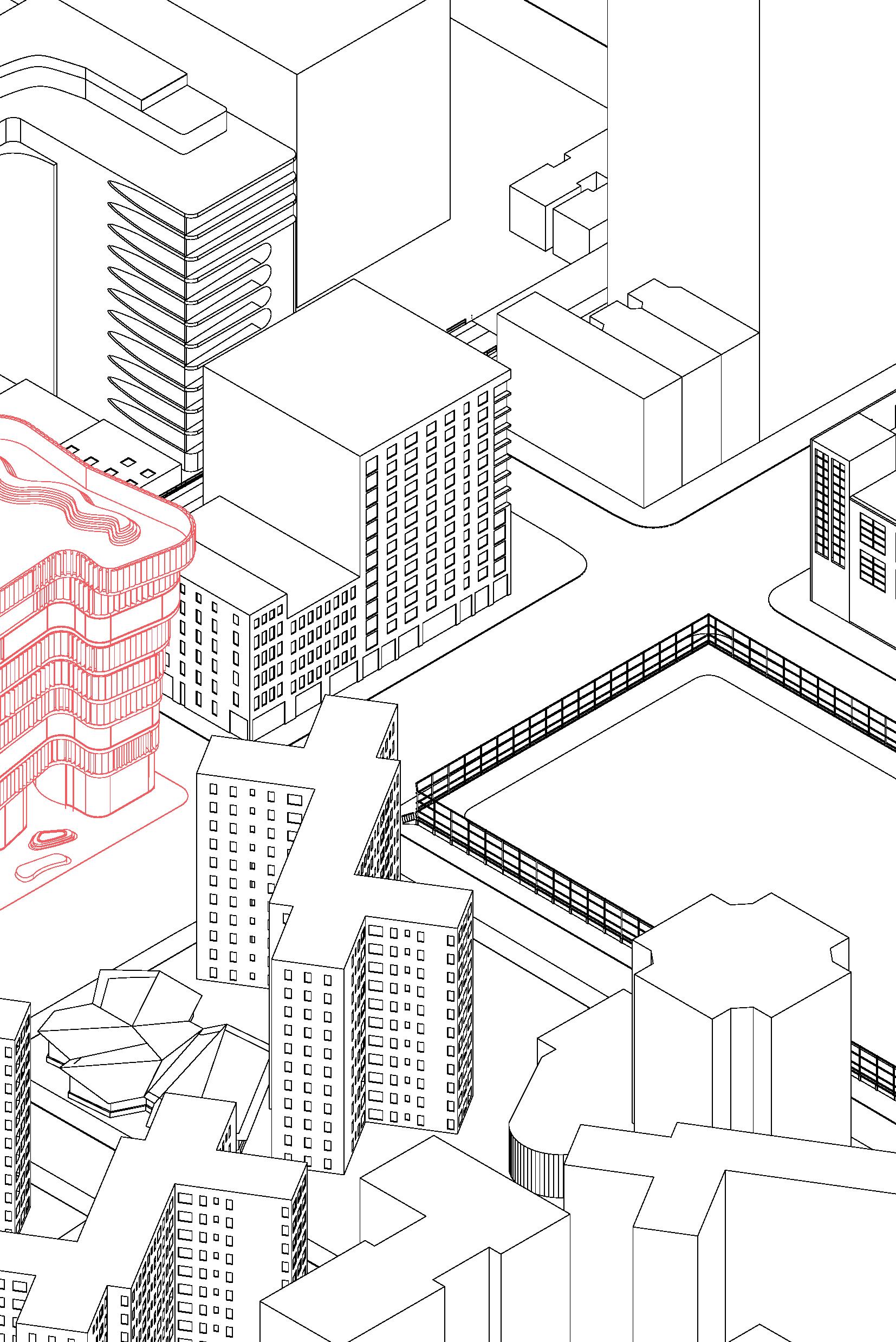
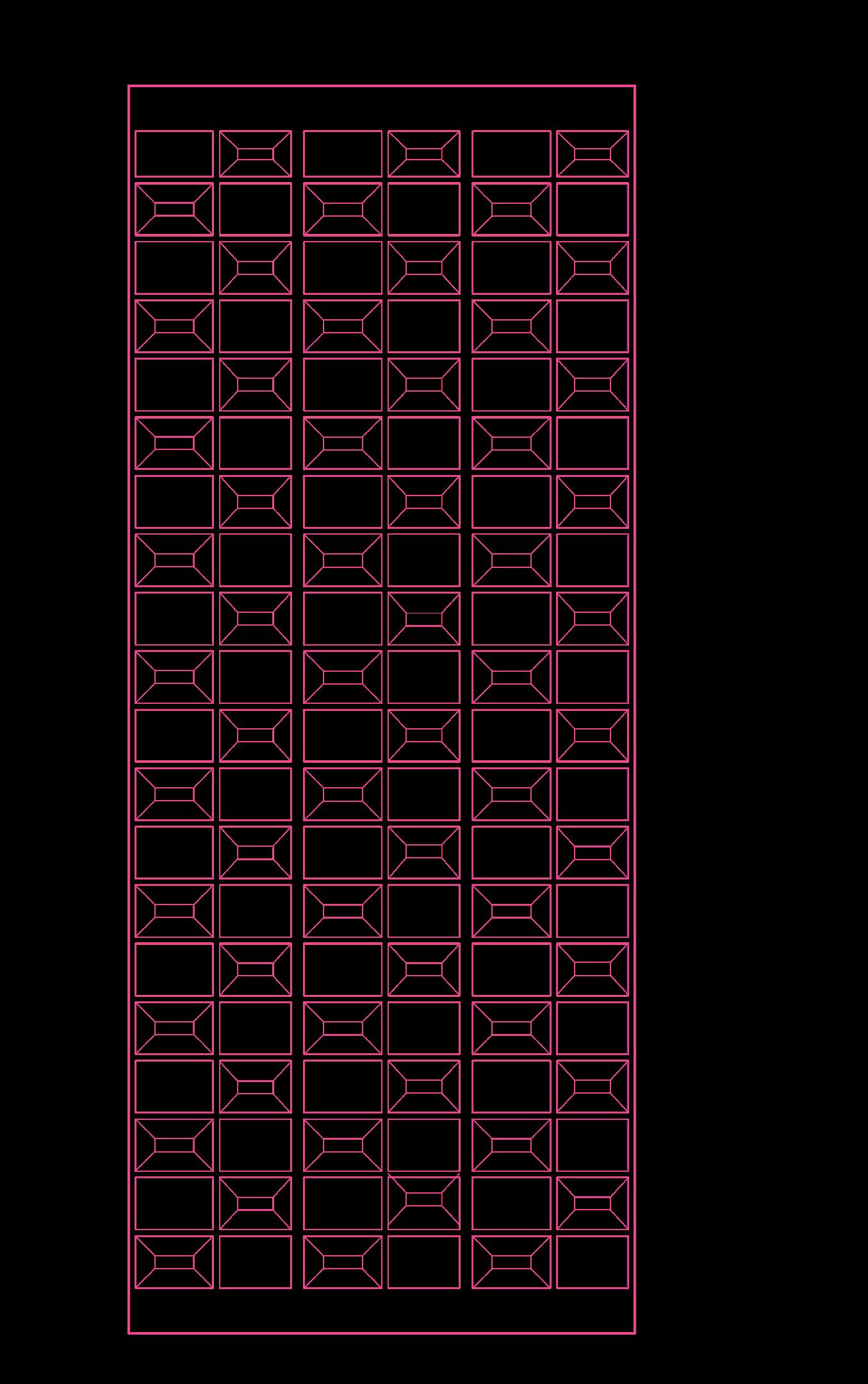
Image: SE Axonometric Site Plan Overlay: Initial Individual Panel Design

26
In the first project regarding urban design fundamentals, building egress codes, and zoning we designed an open floor multi-use building in New York City. The nearby High-line and immediate mid-sized buildings informed how views were views were established per floor. An open floor plan encouraged large co-working spaces that are able to be navigated easily for both workers and visitors. The louver system allows the individual to control and condense light with authority, like a light dimmer. With the control of an app, the movable facade can change for a certain condition, a view or used to create a movable facade.


29
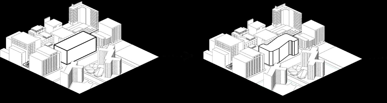
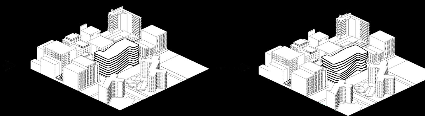
Image (TOP): Front Elevation Image (BOTTOM): Process Diagram


28
Image (LEFT): Exploded Floor Plan
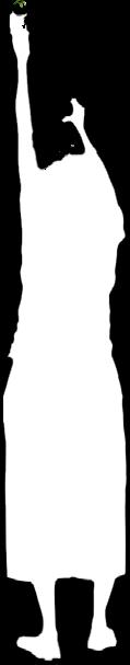
Image (RIGHT TOP): Top View Panel Design
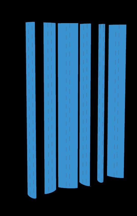
Image (RIGHT BOTTOM): Wall Panel Perspective

29
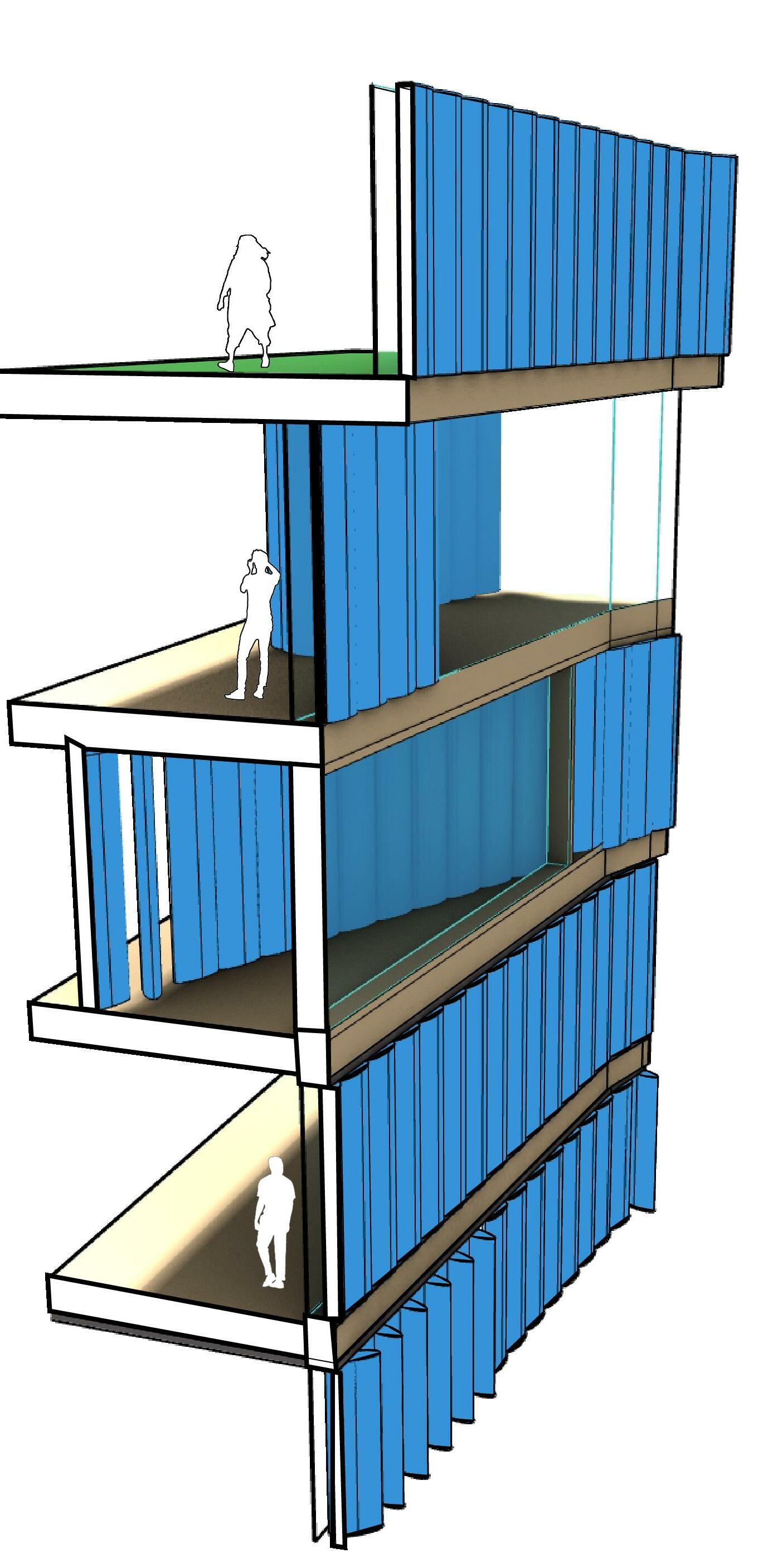
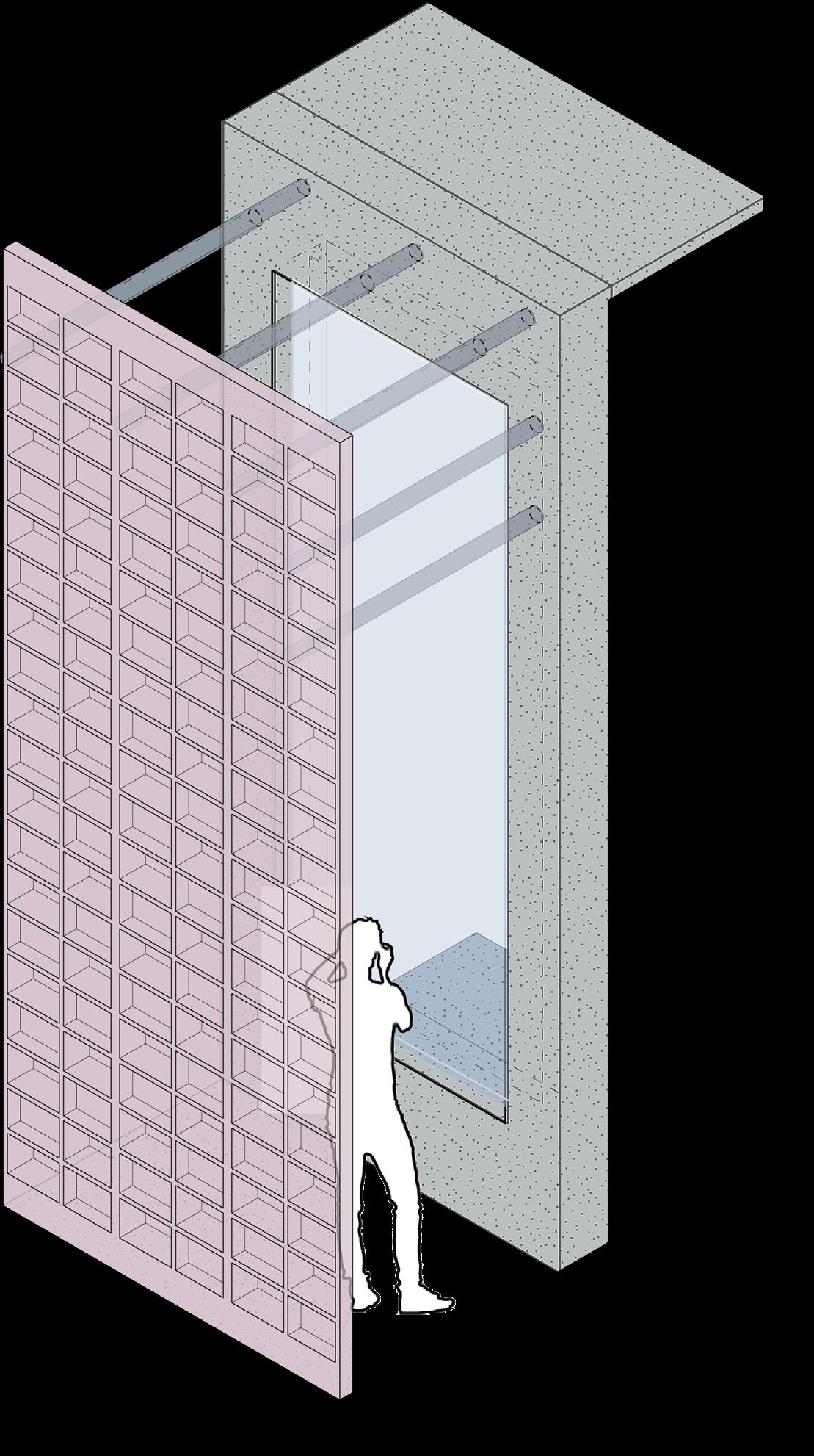
The louver system is created by individual 2’ x 11’ louver panels fixed on a 13’ rod .This allows for the panels to rotate around the pin. Each rod and panel is attached to a rail system. Every floor has a unique rail system. The initial idea was to have each louver individually moved by hand, but after discovering the projected weight of each panel, having panels rotated by automation by app was more believable. Additionally adding that louvers can be moved in groups of 5 or more and individually was also suggested.
30
Image: Tectonic Section
transparency
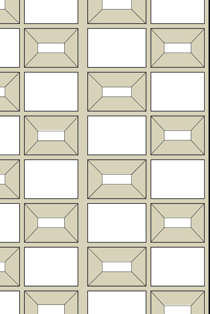 Image: Initial Panel Design Overlay
ARCH 4010: Diplomacy Studio
Professor Dr. Carlos Barrios Kleiss
Fall 2022
Transparency
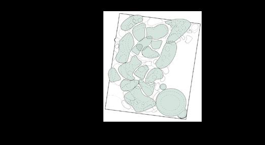
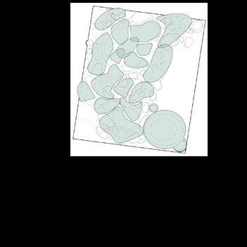
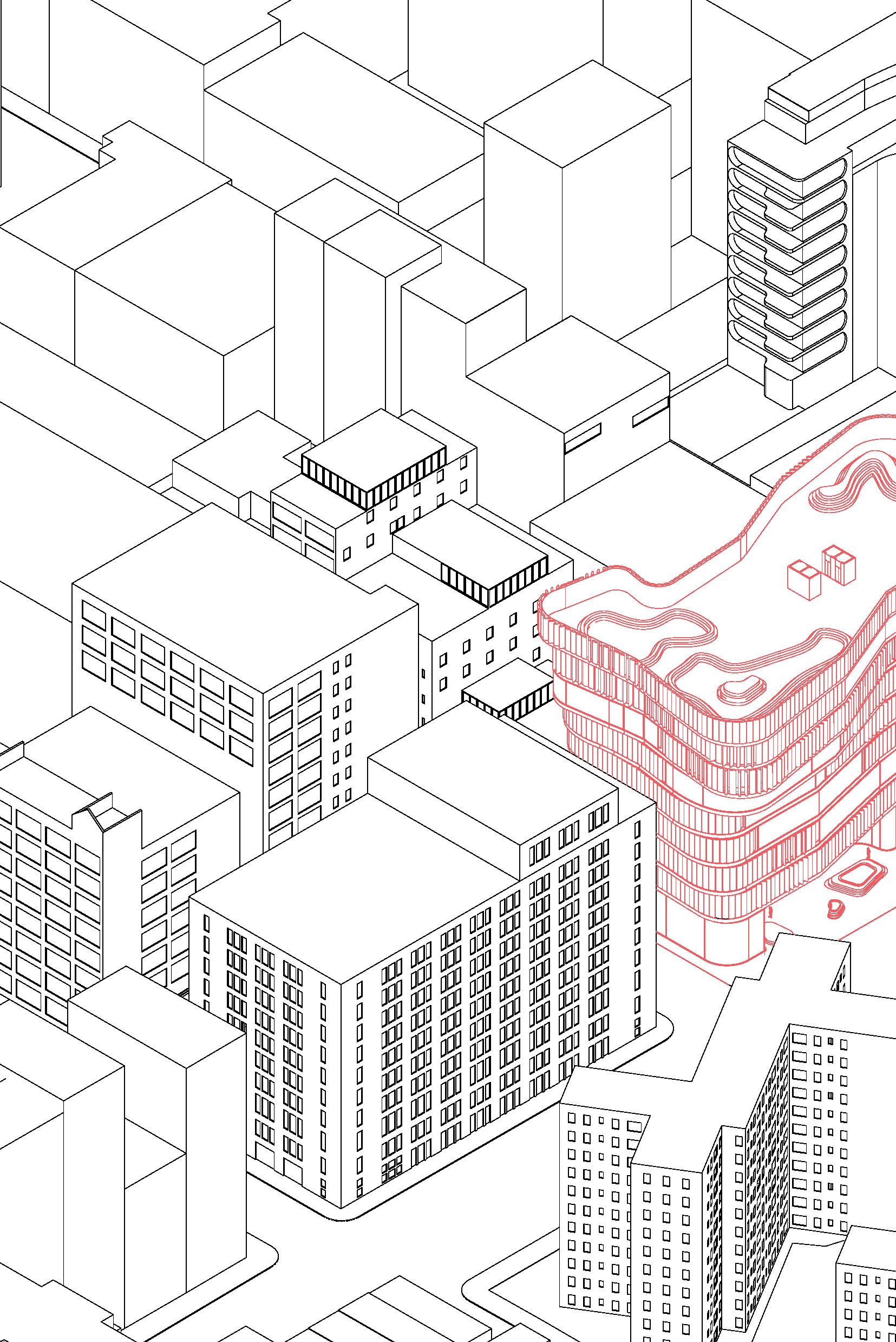
Image: Axonometric Site Plan with Immediate Site Outline
35
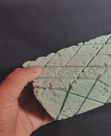
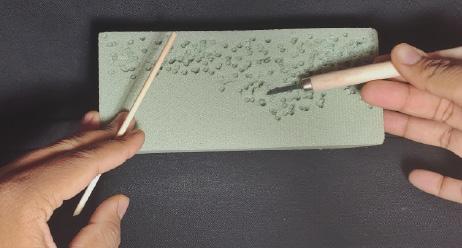
For this project, we were tasked with designing a United States embassy in Santiago, Chile in conjuncture with KCCT Architects in Washington, D.C. We had the pleasure of meeting with them many times throughout the semester. Though we were asked to create renovation plans for the already established embassy, The decision to remodel the entire site. The concept of “transparency” came from many conversations with professors and students about how to design in a foreign country with American history in mind. By making the design more transparent,thissymbolizes a desire for more open American outreach in regards to diplomacy. We also mentored by our local Precast Concrete Institute (PCI) chapter to study precast concretes contribution to architecture industry worldwide and its properties.
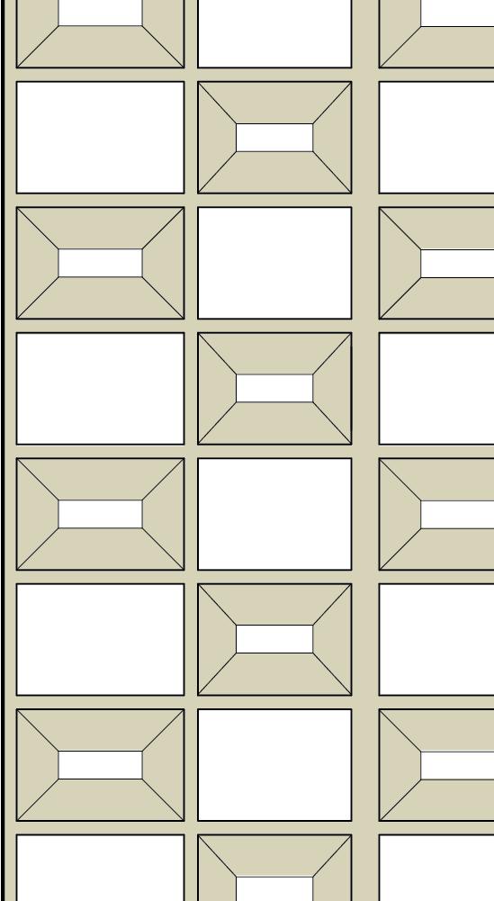
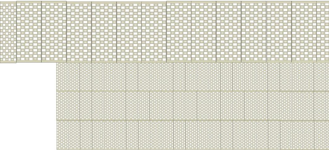
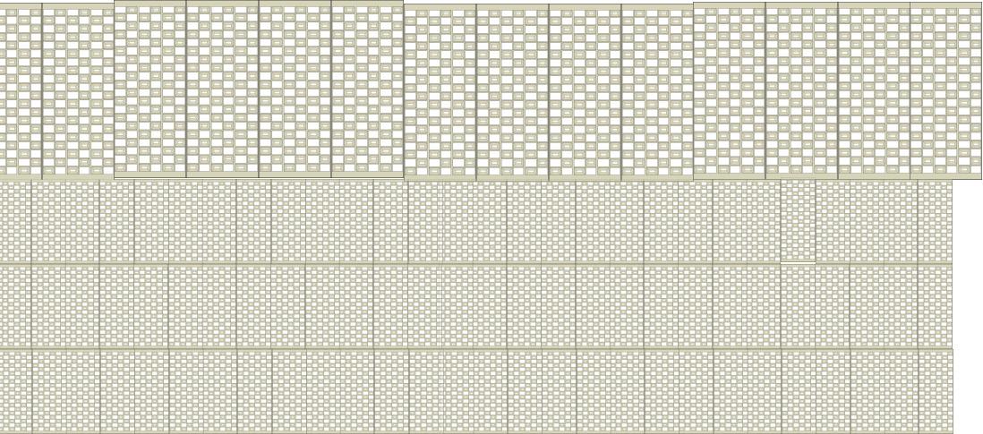
Image (LEFT): Tectonic Wall Section Image (RIGHT): Initial Wall Panel Diagram
36
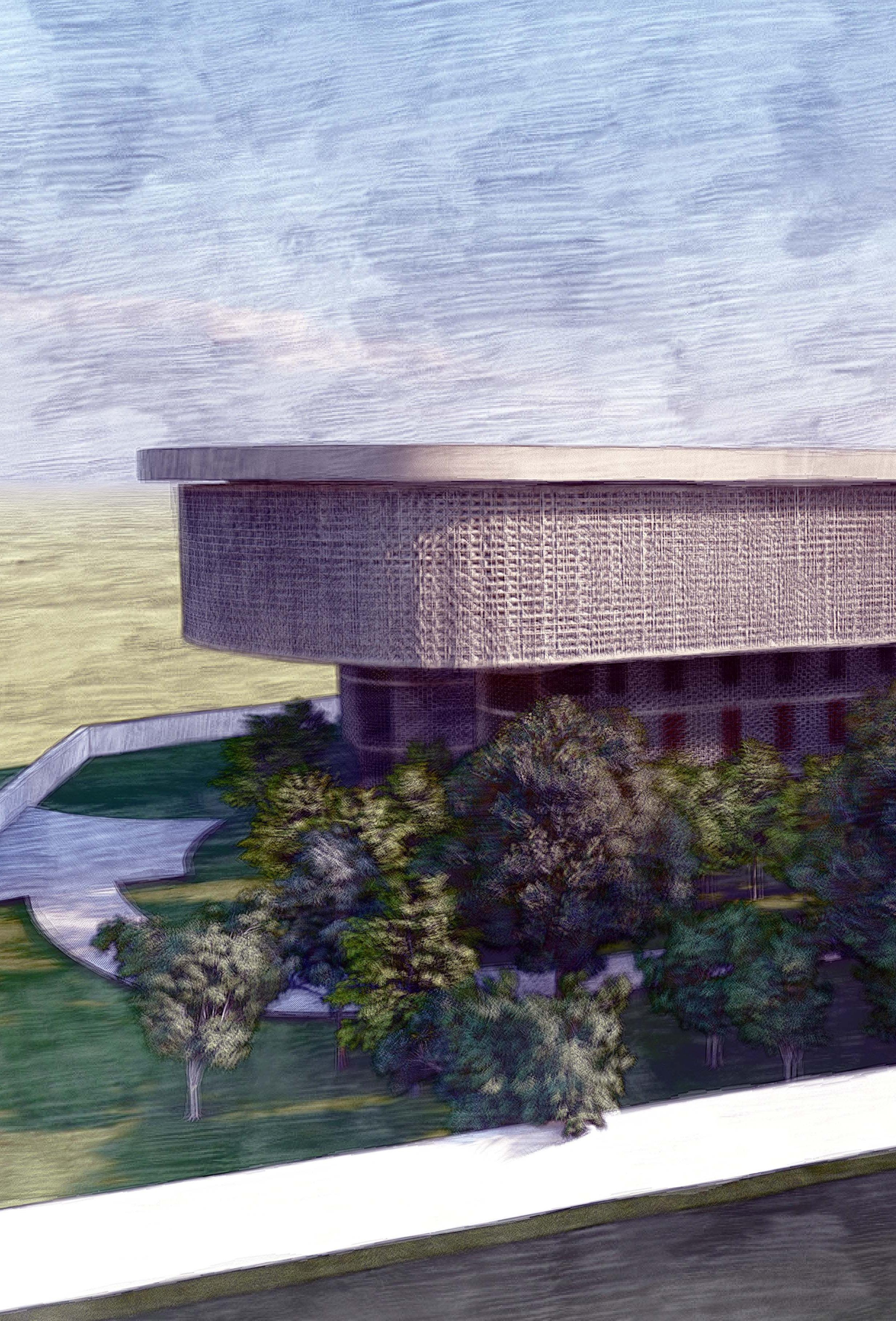
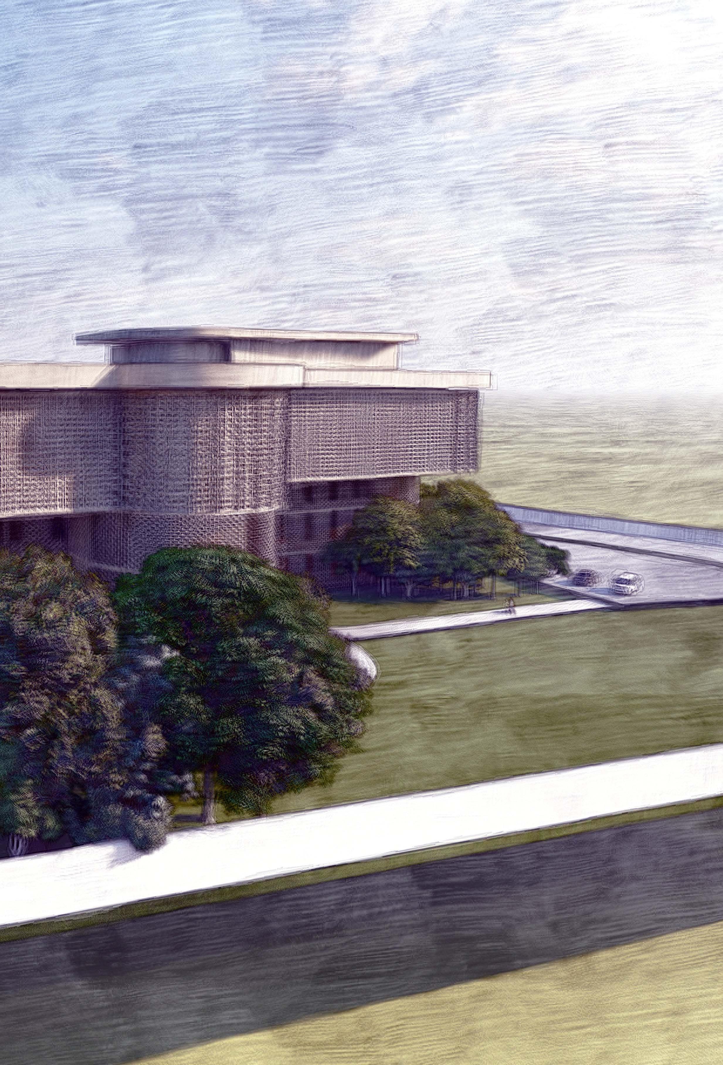 Image: Bird’s Eye Exterior Rendering

39
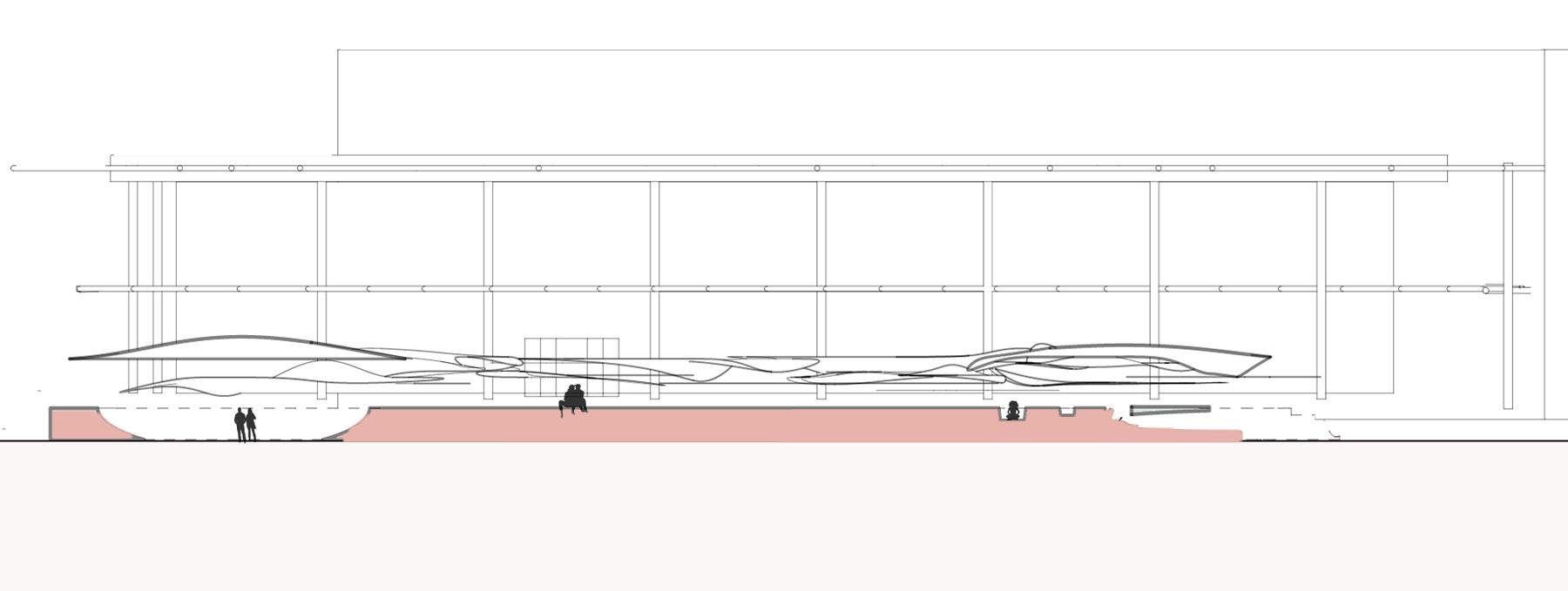
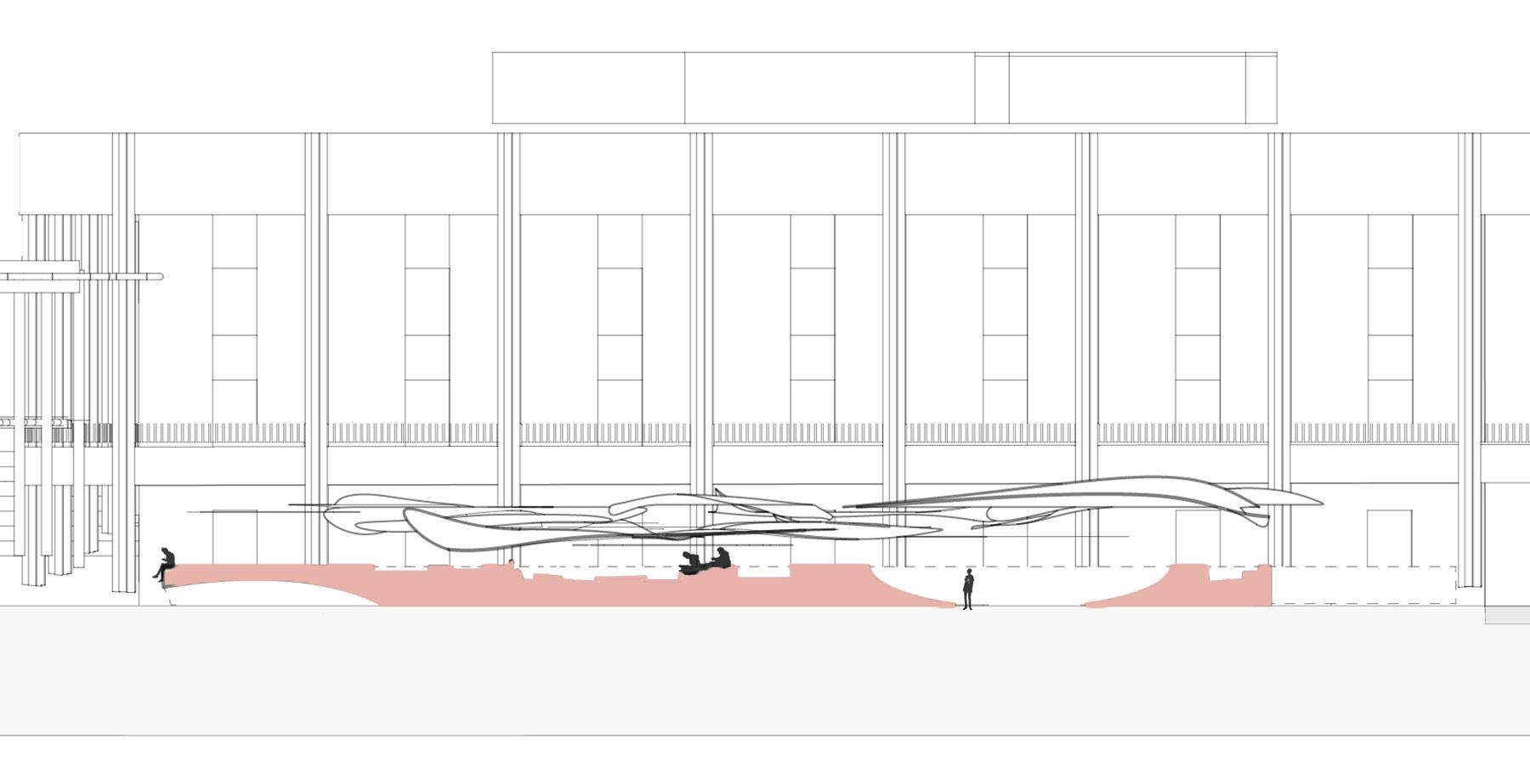
Image (TOP): Front Elevation Images (BOTTOM FROM LEFT TO RIGHT): Left, Back and Right Elevations


40
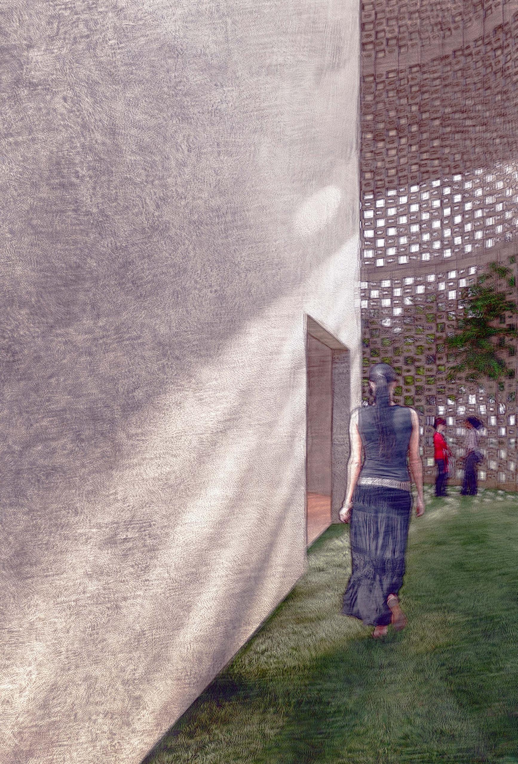
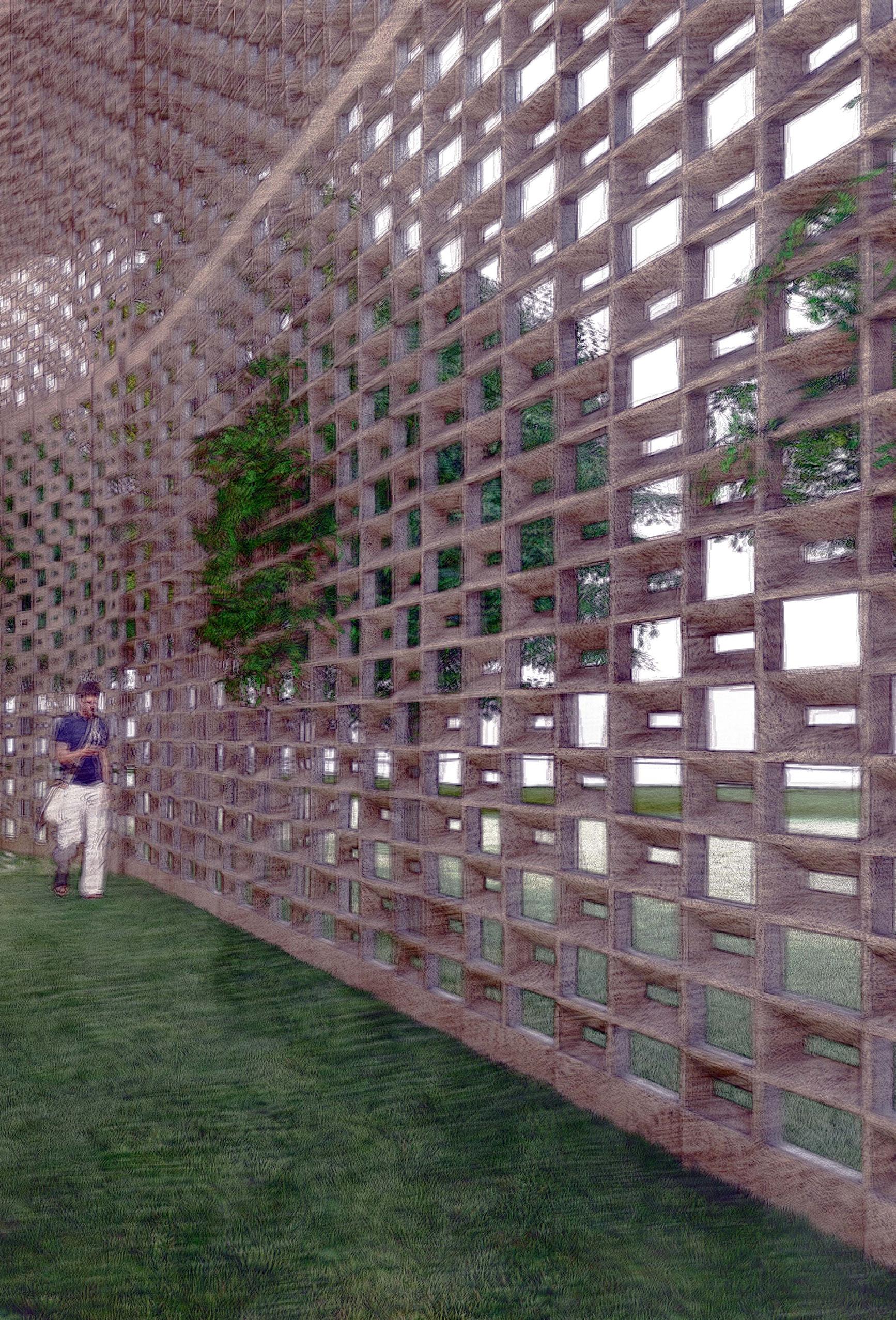 Image: Interior Rendering