Shigleys Mechanical Engineering Design 10th Edition Budynas Solutions Manual
To download the complete and accurate content document, go to: https://testbankbell.com/download/shigleys-mechanical-engineering-design-10th-editi on-budynas-solutions-manual/
Shigleys Mechanical Engineering Design 10th Edition Budynas Solutions Manual Visit TestBankBell.com to get complete for all chapters
Chapter 8
Notes to the Instructor.
1. For Problems 8-33 through 8-44 and 8-51 through 8-58. There is a statement preceding Prob. 8-33 which covers a change which will be corrected in the second printing of the 10th edition.
2. For Probs. 8-41 to 8-44. These problems, as well as many others in this chapter are best implemented using a spreadsheet
8-1
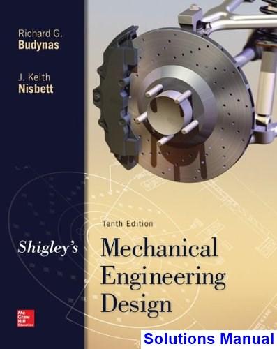
(a) Thread depth= 2.5 mm Ans.
Width = 2 5 mm Ans.
dm = 25 - 1 25 - 1 25 = 22 5 mm
dr = 25 - 5 = 20 mm
l = p = 5 mm Ans.
(b) Thread depth = 2.5 mm Ans.
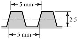
Width at pitch line = 2.5 mm Ans.
dm = 22.5 mm
dr = 20 mm
l = p = 5 mm Ans.
Shigley’s MED, 10th edition Chap. 8 Solutions, Page 1/70
1.226 869 0.649519 1.226 8690.649519 0.938194 2 r m ddp ddp dpdp ddp =− =− −+− ==− 2 2(0.938194) . 44 t d AdpAns ==− 8-3
(c)
8-2, tan 1tan R f PF f + =
8-2 From Table 8-1,
From Eq.
of Sec.
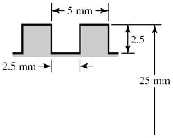
Using f = 0 08, form a table and plot the efficiency curve.
8-4 Given F = 5 kN, l = 5 mm, and dm = d p/2 = 25 5/2 = 22.5 mm, the torque required to raise the load is found using Eqs. (8-1) and (8-6)
The torque required to lower the load, from Eqs. (8-2) and (8-6) is
Since TL is positive, the thread is self-locking. From Eq.(8-4) the efficiency is
8-5 Collar (thrust) bearings, at the bottom of the screws, must bear on the collars. The bottom segment of the screws must be in compression. Whereas, tension specimens and their grips must be in tension. Both screws must be of the same-hand threads.
Shigley’s MED, 10th edition Chap. 8 Solutions, Page 2/70 tan 221tan Rmm R PdFdf T f + == 0 /(2)1tan1tan tan . /2tantan Rm TFlff eAns TFdff === ++
, deg. e 0 0 0 0.678 20 0.796 30 0.838 40 0.8517 45 0.8519
( ) ( ) ( ) ( ) ( ) 522.550.0922.550.0645 15.85Nm. 222.50.0952 R TAns + =+=
( ) ( ) ( ) ( ) ( ) 522.50.0922.5550.0645 7.83Nm. 222.50.0952 L TAns =+= +
( ) ( ) 55 0.251. 215.85 eAns ==
8-6 Screws rotate at an angular rate of
(a) The lead is 0.25 in, so the linear speed of the press head is
Shigley’s MED, 10th edition Chap. 8 Solutions, Page 3/70
60 n ==
172028.67rev/min
V = 28.67(0
o 20.25/21.875in sec 1/cos(29/2)1.033 m d =−= == Eq. (8-5): 2500(1.875)0.25(0.05)(1.875)(1.033) 221.0 lbf ·in 2(1.875)0.05(0.25)(1.033) RT + == Eq. (8-6): 2500(0.08)(3.5/2)350lbf
350221.0571lbf
in/screw 571(2)20.04lbf ·in 60(0.95) 6320.04(1720)0.547hp. 02563025 c total motor T T T Tn HAns == =+= == === 8-7 L = 3.5 in, T = 3.5 F, M = (L 3/8) F = (3.5 0.375) F = 3.125 F, Sy = 41 kpsi. 33 3232(3.125) 41000 (0.1875) y MF S d ==== F = 8.49 lbf T = 3.5(8.49) = 29.7 lbf ∙ in Ans. (b) Eq. (8-5), 2= 60 , l = 1/10 = 0 1 in, f = 0 15, sec = 1 155, p = 0.1 in ( ) clamp clamp clamp 3 0.6495190.10.6850in 4 (0.6850) 0.1(0.15)(0.6850)(1.155) 2(0.6850)0.15(0.1)(1.155) 0.07586 29.7 392lbf . 0.075860.07586 m R R R d F T TF T FAns =−= + = = ===
25) = 7.17 in/min Ans. (b) F = 2500 lbf/screw
·in
·
(c) The column has one end fixed and the other end pivoted. Base the decision on the mean diameter column. Input: C =
(d) This is a subject for class discussion.
Shigley’s MED, 10th edition Chap. 8 Solutions, Page 4/70
1.2, D
0.685
A = (0.6852)/4 = 0.369in2 , Sy = 41 kpsi, E = 30(106) psi, L = 6 in, k = D/4 =0.171 25 in, L/k = 35.04. From Eq. (4-45), ( ) ( ) 1/2 1/2 26 2 1 21.23010 2 131.7 41000 y lCE kS ===
Eq.
( ) ( ) ( ) ( ) 2 clampcr 2 3 33 6 1 2 41101 0.369411035.0414.610lbf 21.23010 y y S l FPAS kCE Ans ==− =−=
=
in,
From
(4-46), the limiting clamping force for buckling is
8-8 T = 8(3.5) = 28 lbf in 310.6667in 412 m d =−= l = 1 6 = 0.1667 in, = 029 2 = 14.50, sec 14.50 = 1.033 From Eqs. (8-5) and (8-6) ( )( )( ) ( ) ( )( ) ( ) total 0.16670.150.66671.0330.151 0.6667 0.1542 20.66670.150.16671.0332 F F TF + =+= 28182lbf. 0.1542 FAns == 8-9 dm = 1.5 0.25/2 = 1.375 in, l = 2(0.25) = 0.5 in From Eq. (8-1) and Eq. (8-6),
Shigley’s MED, 10th edition Chap. 8 Solutions, Page 5/70 ( ) ( )33 2.210(1.375)2.210(0.15)(2.25) 0.5(0.10)(1.375) 2(1.375)0.10(0.5)2 330371701lbf ·in RT + =+ =+=
0.5
rev/s
240 rev/min so the power is ( )701240 2.67hp. 6302563025 Tn HAns === 8-10 dm = 40 4
36 mm, l = p = 8 mm
Eqs. (8-1) and (8-6) 368(0.14)(36)0.09(100) 2(36)0.14(8)2 (3.8314.5)8.33 N·m( inkN) 22(1)2 rad/s 3000 477N·m 2 477 57.3kN . 8.33 FF T FFF n HT H T FAns + =+ =+= === = === == 57.3(8) 0.153 . 22(477) Fl eAns T === 8-11 (a) Table A-31, nut height H = 12.8 mm. L ≥ l + H = 2(15) + 12.8 = 42.8 mm. Rounding up, L = 45 mm Ans. (b) From Eq. (8-14), LT = 2d + 6 = 2(14) +6 = 34 mm From Table 8-7, ld = L LT = 45 34 = 11 mm, lt = l ld = 2(15) 11 = 19 mm, Ad = (142) / 4 = 153.9 mm2. From Table 8-1, At = 115 mm2. From Eq. (8-17) ( ) ( ) ( ) 153.9115207 874.6MN/m. 153.91911511 dt b dttd AAE kAns AlAl === ++ (c) From Eq. (8-22), with l = 2(15) = 30 mm
Since n = V/l = 2/
= 4
=
=
From
(a) Table A-31, nut height
Shigley’s MED, 10th edition Chap. 8 Solutions, Page 6/70 ( ) ( ) ( ) ( ) ( ) 0.577420714 0.5774 3116.5MN/m. 0.57740.5 0.5774300.514 2ln5 2ln5 0.57742.5 0.5774302.514 m Ed kAns ld ld === + + + + 8-12
H
12.8
A-33,
2(15)
3.5 = 33.5 mm. L ≥ l + H = 33.5 + 12.8 = 46.3 mm.
L = 50 mm Ans. (b) From Eq. (8-14), LT = 2d + 6 = 2(14) +6 = 34 mm From Table 8-7, ld = L LT = 50 34 = 16 mm, lt = l ld = 33.5 16 = 17.5 mm, Ad = (142) / 4 = 153.9 mm2. From Table 8-1, At = 115 mm2. From Eq. (8-17) ( ) ( ) ( ) 153.9115207 808.2MN/m. 153.917.511516 dt b dttd AAE kAns AlAl === ++ (c) From Eq. (8-22) ( ) ( ) ( ) ( ) ( ) 0.577420714 0.5774 2969MN/m. 0.57740.5 0.577433.50.514 2ln5 2ln5 0.57742.5 0.577433.52.514 m Ed kAns ld ld === + + + + 8-13
+ d
= 15 + 14/2 = 22 mm. L ≥ h + 1.5d = 36 mm. Rounding
L = 40
b
2d + 6 = 2(14)
=
=
mm. Table
washer thickness t = 3.5 mm. Thus, the grip is l =
+
Rounding up
(a) Table 8-7, l = h
/2
up
mm Ans. (
) From Eq. (8-14), LT =
+6
34 mm
(
8-14 (a) From Table A-31, the nut height is H = 7/16 in. L ≥ l +
(
Shigley’s MED, 10th edition Chap. 8 Solutions, Page 7/70
d
d
(14
A
115 mm2.
( ) ( ) ( ) 153.9115207 1162.2MN/m. 153.9161156 dt b dttd AAE kAns AlAl === ++
From Table 8-7, ld = L LT = 40 34 = 6 mm, lt = l l
= 22 6 = 16 mm A
=
2) / 4 = 153.9 mm2. From Table 8-1,
t =
From Eq. (8-17)
c
( ) ( ) ( ) ( ) ( ) 0.577420714 0.5774 3624.4MN/m. 0.57740.5 0.5774220.514 2ln5 2ln5 0.57742.5 0.5774222.514 m Ed kAns ld ld === + + + +
) From Eq. (8-22), with l = 22 mm
H = 2 + 1 + 7/16 = 3 7/16 in. Rounding up, L = 3.5 in Ans.
b
1/4
2(0.5)
0.25
1.25 in From Table 8-7, ld = L LT = 3.5 1.25 = 2.25 in, lt = l ld = 3 2.25 = 0.75 in Ad = (0.52)/4 = 0.1963
2
8-2, At = 0.1419 in2.
Eq. (8-17) ( ) ( ) ( ) 0.19630.141930 1.79Mlbf/in. 0.19630.750.14192.25 dt b dttd AAE kAns AlAl === ++
) From Eq. (8-13), LT = 2d +
=
+
=
in
. From Table
From
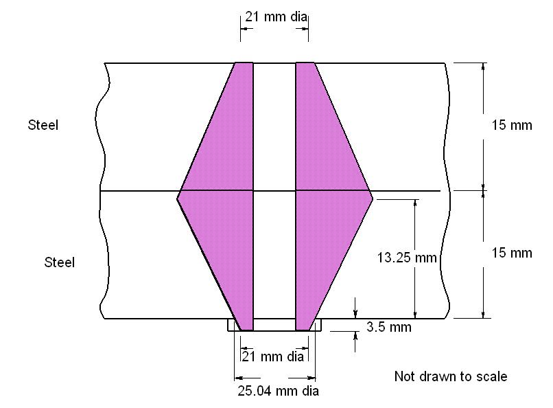
Top steel frustum: t = 1.5 in, d = 0.5 in, D = 0.75 in, E = 30 Mpsi. From Eq. (8-20)
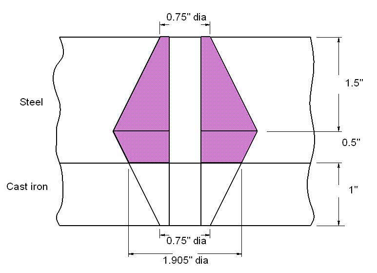
1 0.5774300.5 22.65Mlbf/in
1.1551.50.750.50.750.5
1.1551.50.750.50.750.5
Lower steel frustum: t = 0.5 in, d = 0.5 in, D = 0.75 + 2(1) tan 30 = 1.905 in, E = 30 Mpsi. Eq. (8-20) k2 = 210.7 Mlbf/in
Cast iron: t = 1 in, d = 0.5 in, D = 0.75 in, E = 14.5 Mpsi (Table 8-8). Eq. (8-20)
k3 = 12.27 Mlbf/in
From Eq. (8-18)
km = (1/k1 + 1/k2 +1/k3) 1 = (1/22.65 + 1/210.7 + 1/12.27) 1 = 7.67 Mlbf/in Ans.
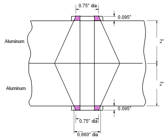
8-15 (a) From Table A-32, the washer thickness is 0.095 in. Thus, l = 2 + 1 + 2(0.095) = 3.19 in. From Table A-31, the nut height is H = 7/16 in. L ≥ l + H = 3.19 + 7/16 = 3.63 in.
Rounding up, L = 3.75 in Ans.
(b) From Eq. (8-13), LT = 2d + 1/4 = 2(0.5) + 0.25 = 1.25 in
From Table 8-7, ld = L LT = 3.75 1.25 = 2.5 in, lt = l ld = 3.19 2.5 = 0.69 in
Ad = (0.52)/4 = 0.1963 in2. From Table 8-2, At = 0.1419 in2. From Eq. (8-17)
Shigley’s MED, 10th edition Chap.
Solutions,
(c)
8
Page 8/70
( ) ( ) ( ) ( ) ( )
ln
k == +−+ ++−
(8-18) km = (2/k1 + 1/k2 +1/k3+1/k
= (2/89.20 + 1/28.99 + 1/234.08 + 1/15.99) 1 = 8.08 Mlbf/in Ans.
)
Shigley’s MED, 10th edition Chap. 8 Solutions, Page 9/70 ( ) ( ) ( ) 0.19630.141930 1.705Mlbf/in. 0.19630.690.14192.5 dt b dttd AAE kAns AlAl === ++ (c)
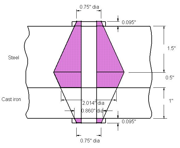
steel washer frustum: t = 0.095 in, d = 0.531 in (Table A-32), D = 0.75 in, E = 30 Mpsi. From Eq. (8-20) ( ) ( ) ( ) ( ) ( ) 1 0.5774300.531 89.20Mlbf/in 1.1550.0950.750.5310.750.531 ln 1.1550.0950.750.5310.750.531 k == +−+ ++− Top plate, top steel frustum: t = 1.5 in, d = 0.5 in, D = 0.75 + 2(0.095) tan 30 = 0.860 in, E = 30 Mpsi. Eq. (8-20) k2 = 28.99 Mlbf/in Top plate, lower steel frustum: t = 0.5 in, d = 0.5 in, D = 0.860 + 2(1) tan 30 = 2.015 in, E = 30 Mpsi. Eq. (8-20) k3 = 234.08 Mlbf/in Cast iron: t = 1 in, d = 0.5 in, D = 0.75 + 2(0.095) tan 30 = 0.860 in, E = 14.5 Mpsi (Table 8-8). Eq. (8-20) k4 = 15.99 Mlbf/in From Eq.
4
8-16 (a) From Table 8-7, l = h + d /2 = 2 + 0.5/2 = 2.25 in. L ≥ h + 1.5 d = 2 + 1.5(0.5) = 2.75 in Ans. (b)
LT = 2d + 1/4
2(0.5) + 0.25
1.25 in ld = L LT = 2.75 1.25 = 1.5 in, lt = l ld = 2.25 1.5 = 0.75 in
Each
1
From Table 8-7,
=
=
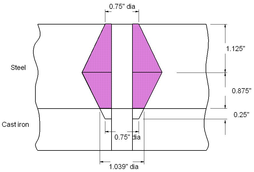
Shigley’s MED, 10th edition Chap. 8 Solutions, Page 10/70 Ad = (0.52)/4 = 0.1963 in2. From Table 8-2, At = 0.1419 in2. From Eq. (8-17) ( ) ( ) ( ) 0.19630.141930 2.321Mlbf/in. 0.19630.750.14191.5 dt b dttd AAE kAns AlAl === ++ (c) Top steel frustum: t = 1.125 in, d = 0.5 in, D = 0.75 in, E = 30 Mpsi. From Eq. (8-20) ( ) ( ) ( ) ( ) ( ) 1 0.5774300.5 24.48Mlbf/in 1.1551.1250.750.50.750.5 ln 1.1551.1250.750.50.750.5 k == +−+ ++− Lower steel frustum: t = 0.875 in, d = 0.5 in, D = 0.75 + 2(0.25) tan 30 = 1.039 in, E = 30 Mpsi. Eq. (8-20) k2 = 49.36
From
km
k1
1/k2 +1/k3) 1 = (1/24.48
1/49.36
8-17 a) Grip, l = 2(2
0.095)
4.19 in. L ≥ 4.19
7/16
4.628 in. Rounding up, L
4.75 in Ans. (b) From Eq. (8-13), LT = 2d + 1/4 = 2(0.5)
0.25
1.25 in
Mlbf/in Cast iron: t = 0.25 in, d = 0.5 in, D = 0.75 in, E = 14.5 Mpsi (Table 8-8). Eq. (8-20) k3 = 23.49 Mlbf/in
Eq. (8-18)
= (1/
+
+
+ 1/23.49) 1 = 9.645 Mlbf/in Ans.
+
=
+
=
=
+
=
Upper and lower halves are the same. For the upper half, Steel frustum: t = 0.095 in, d = 0.531 in, D = 0.75 in, and E = 30 Mpsi. From Eq. (8-20)
2 in, d = 0.5 in, D =0.75 + 2(0.095) tan 30 = 0.860 in, and E = 10.3 Mpsi. Eq. (8-20) k2 = 9.24 Mlbf/in
For the top half, m k = (1/k1 + 1/k2) 1 = (1/89.20 + 1/9.24) 1 = 8.373 Mlbf/in
Since the bottom half is the same, the overall stiffness is given by
8.373/2 = 4.19 Mlbf/in Ans
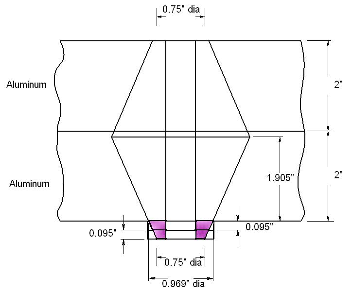
8-18 (a) Grip, l = 2(2 + 0.095) = 4.19 in. L ≥ 4.19 + 7/16 = 4.628 in. Rounding up, L = 4.75 in Ans.
(b) From Eq. (8-13), LT = 2d + 1/4 = 2(0.5) + 0.25 = 1.25 in
Shigley’s MED, 10th edition Chap. 8 Solutions, Page 11/70
d = L LT = 4.75 1.25 = 3.5 in, lt = l ld = 4.19 3.5 = 0.69 in Ad = (0.52)/4 = 0.1963 in2. From Table 8-2, At = 0.1419 in2. From Eq. (8-17) ( ) ( ) ( ) 0.19630.141930 1.322Mlbf/in. 0.19630.690.14193.5 dt b dttd AAE kAns AlAl === ++ (c)
From Table 8-7, l
( ) ( ) ( ) ( ) ( ) 1 0.5774300.531 89.20Mlbf/in 1.1550.0950.750.5310.750.531 ln 1.1550.0950.750.5310.750.531 k == +−+ ++− Aluminum: t =
km
(1/ m k
1/ m k
1
m k
=
+
)
=
/2 =
= 4 2.095 = 1.905 in, d = 0.5 in, D = 0.75 +4(0.095) tan 30 = 0.969 in, and E = 10.3 Mpsi. Eq. (8-20) k2 = 11.34 Mlbf/in
Steel washers frustum: t = 2(0.095) = 0.190 in, d = 0.531 in, D = 0.75 in, and E = 30 Mpsi. Eq. (8-20) k3 = 53.91 Mlbf/in
Eq. (8-18)
+ 1/53.91) 1 = 4.08 Mlbf/in Ans. 8-19 (a) From Table A-31, the nut height is H = 8.4 mm. L > l + H = 50 + 8.4 = 58.4 mm.
Rounding up, L = 60 mm Ans.
Shigley’s MED, 10th edition Chap. 8 Solutions, Page 12/70 From Table 8-7, ld = L LT = 4.75 1.25 = 3.5 in, lt = l ld = 4.19 3.5 = 0.69 in Ad = (0.52)/4 = 0.1963 in2. From Table 8-2, At = 0.1419 in2. From Eq. (8-17) ( ) ( ) ( ) 0.19630.141930 1.322Mlbf/in. 0.19630.690.14193.5 dt b dttd AAE kAns AlAl === ++ (c) Upper aluminum frustum: t = [4 + 2(0.095)] /2 = 2.095 in, d = 0.5 in, D = 0.75 in, and E = 10.3 Mpsi. From Eq. (8-20) ( ) ( ) ( ) ( ) ( ) 1 0.577410.30.5 7.23Mlbf/in 1.1552.0950.750.50.750.5 ln 1.1552.0950.750.50.750.5 k == +−+ ++− Lower aluminum frustum: t
From
km
k1
1/k2 +1/k3) 1 = (1/7.23
1/11.34
= (1/
+
+
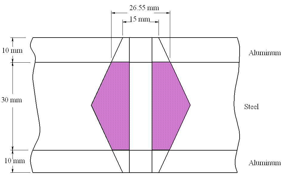
(b) From Eq. (8-14), LT = 2d + 6 = 2(10) + 6 = 26 mm, ld = L LT = 60 26 = 34 mm, lt = l l = 50 34 = 16 mm. Ad = (102) / 4 = 78.54 mm2. From Table 8-1, At = 58 mm2. From Eq. (8-17)
Upper and lower frustums are the same. For the upper half, Aluminum: t = 10 mm, d = 10 mm, D = 15 mm, and from Table 8-8, E = 71 GPa. From Eq. (8-20)
Steel: t = 15 mm, d = 10 mm, D = 15 + 2(10) tan 30 = 26.55 mm, and E = 207 GPa. From Eq. (8-20)
Since the bottom half is the same, the overall stiffness is given by
Shigley’s MED, 10th edition Chap. 8 Solutions, Page 13/70
( ) ( ) ( ) 78.5458.0207 292.1MN/m. 78.541658.034 dt b dttd AAE kAns AlAl === ++ (c)
( ) ( ) ( ) ( ) ( ) 1 0.57747110 1576MN/m 1.1551015101510 ln 1.1551015101510 k == +−+ ++−
( ) ( ) ( ) ( ) ( ) 2 0.577420710 11440MN/m 1.1551526.551026.5510 ln 1.1551526.551026.5510 k == +−+ ++−
m k = (1/k1 + 1/k2) 1 = (1/1576 + 1/11 440) 1 = 1385 MN/m
For the top half,
km = (1/ m k + 1/ m k ) 1 = m k /2 = 1385/2 = 692.5 MN/m Ans.
8-20 (a) From Table A-31, the nut height is
Shigley’s MED, 10th edition Chap. 8 Solutions, Page 14/70
8.4 mm. L > l + H = 60 + 8.4
68.4
b
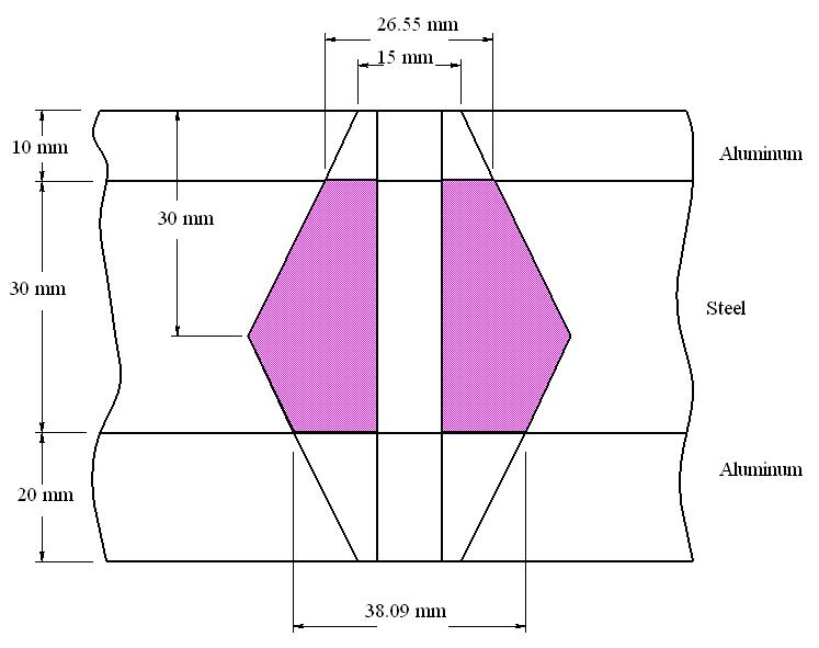
LT = 2d + 6 = 2(10) + 6 = 26 mm, ld = L LT = 70 26 = 44 mm, lt = l ld = 60 44 = 16 mm. Ad = (102) / 4 = 78.54 mm2. From Table 8-1, At =
mm2
Eq. (8-17) ( ) ( ) ( ) 78.5458.0207 247.6MN/m. 78.541658.044 dt b dttd AAE kAns AlAl === ++ (c)
( ) ( ) ( ) ( ) ( ) 1 0.577410.371 1576MN/m 1.1552.09515101510 ln 1.1552.09515101510 k == +−+ ++−
MN/m
frustum:
20 mm, d = 10 mm, D = 15 + 2(10) tan 30 = 26.55 mm, and E = 207 GPa. Eq.
k3 = 9 781 MN/m
H =
=
mm. Rounding up, L = 70 mm Ans. (
) From Eq. (8-14),
58
. From
Upper aluminum frustum: t = 10 mm, d = 10 mm, D = 15 mm, and E = 71 GPa. From Eq. (8-20)
Lower aluminum frustum: t = 20 mm, d = 10 mm, D = 15 mm, and E = 71 GPa Eq. (8-20) k2 = 1 201
Top steel
t =
(8-20)
Lower steel frustum: t = 10 mm, d = 10 mm, D = 15 + 2(20) tan 30 = 38.09 mm, and E = 207 GPa. Eq. (8-20) k4 = 29 070 MN/m
= 623.5 MN/m Ans.
(a) From Table 8-7, l = h + d /2 = 10 + 30 + 10/2 = 45 mm. L ≥ h + 1.5 d = 10 + 30 + 1.5(10) = 55 mm Ans. (b) From Eq. (8-14), LT =
Shigley’s
edition Chap. 8
15/70
MED, 10th
Solutions, Page
From
m
k
2
k3+1/k4) 1 = (1/1 576 + 1/1 201
1/9
1
2(10)
= 16 mm. Ad = (102) / 4 = 78.54 mm2.
t
(8-17) ( ) ( ) ( ) 78.5458.0207 320.9MN/m. 78.541658.029 dt b dttd AAE kAns AlAl === ++ (c) Upper aluminum frustum: t = 10 mm, d = 10 mm, D = 15 mm, and E = 71 GPa. From Eq. (8-20) ( ) ( ) ( ) ( ) ( ) 1 0.577410.371 1576MN/m 1.1552.09515101510 ln 1.1552.09515101510 k == +−+ ++− Lower aluminum frustum: t
5 mm, d = 10 mm, D = 15 mm, and E = 71 GPa. Eq. (8-20) k2
2 300 MN/m Top steel frustum: t = 12.5 mm, d = 10 mm, D = 15 + 2(10) tan 30 = 26.55 mm, and E = 207 GPa. Eq. (8-20) k3 = 12 759 MN/m
Eq. (8-18) k
= (1/
1 + 1/k
+1/
+
781 +1/29 070)
8-21
2d + 6 =
+ 6 = 26 mm, ld = L LT = 55 26 = 29 mm, lt = l ld = 45 29
From Table 8-1, A
= 58 mm2. From Eq.
=
=
Lower steel frustum: t = 17.5 mm, d = 10 mm, D = 15 + 2(5) tan 30 = 20.77 mm, and E = 207 GPa. Eq. (8-20) k4 = 6 806 MN/m
See Table 8-7 for other terms used. Using a spreadsheet, with coarse-pitch bolts (units are mm,
Use a M14 2 bolt, with length 55 mm. Ans.
8-23 Equation (f ), p. 428:
C
=
Shigley’s
edition Chap. 8
16/70
MED, 10th
Solutions, Page
From Eq. (8-18) km = (1/k1 + 1/k2 +1/k3+1/k4) 1 = (1/1 576 + 1/2 300 + 1/12 759 +1/6 806) 1
772.4 MN/m Ans. 8-22
b bm k C kk = + Eq.
dt b dttd AAE k AlAl = + Eq. (8-22): ( ) ( ) ( ) 0.5774207 0.5774400.5 2ln5 0.5774402.5 m d k d d = + +
=
Equation (f ), p. 428:
(8-17):
d At Ad H L > L LT 10 58 78.53982 8.4 48.4 50 26 12 84.3 113.0973 10.8 50.8 55 30 14 115 153.938 12.8 52.8 55 34 16 157 201.0619 14.8 54.8 55 38 20 245 314.1593 18 58 60 46 24 353 452.3893 21.5 61.5 65 54 30 561 706.8583 25.6 65.6 70 66 d l ld lt kb km C 10 40 24 16 356.0129 1751.566 0.16892 12 40 25 15 518.8172 2235.192 0.188386 14 40 21 19 686.2578 2761.721 0.199032 16 40 17 23 895.9182 3330.796 0.211966 20 40 14 26 1373.719 4595.515 0.230133 24 40 11 29 1944.24 6027.684 0.243886 30 40 4 36 2964.343 8487.533 0.258852
mm2, MN/m):
b bm k
kk
+
For upper frustum, Eq. (8-20), with D = 1.5 d and t = 1.5 in:
Lower steel frustum, with D = 1.5d + 2(1) tan 30 = 1.5d + 1.155, and t = 0.5 in:
For cast iron frustum, let E = 14. 5 Mpsi, and D = 1.5 d, and t = 1 in:
Overall, km = (1/k1 +1/k2 +1/k3) 1
See Table 8-7 for other terms used. Using a spreadsheet, with coarse-pitch bolts (units are in, in2, Mlbf/in):
Shigley’s MED, 10th edition Chap. 8 Solutions, Page 17/70 Eq. (8-17): dt b dttd AAE k AlAl = +
( ) ( ) ( ) ( ) ( ) ( ) ( ) ( ) 1 0.5774300.577430 1.1551.50.52.51.7330.5 lnln5 1.1551.52.50.51.7332.5 dd k d dd d dd == + + + +
( ) ( )( ) ( )( ) 2 0.577430 1.7330.52.51.155 ln 1.7332.50.51.155 d k dd dd = ++ ++
( ) ( ) ( ) 3 0.577414.5 1.1550.5 ln5 1.1552.5 d k d d = + +
Shigley’s MED, 10th edition Chap. 8 Solutions, Page 18/70 d At Ad H L > L LT l 0.375 0.0775 0.110447 0.328125 3.328125 3.5 1 3 0.4375 0.1063 0.15033 0.375 3.375 3.5 1.125 3 0.5 0.1419 0.19635 0.4375 3.4375 3.5 1.25 3 0.5625 0.182 0.248505 0.484375 3.484375 3.5 1.375 3 0.625 0.226 0.306796 0.546875 3.546875 3.75 1.5 3 0.75 0.334 0.441786 0.640625 3.640625 3.75 1.75 3 0.875 0.462 0.60132 0.75 3.75 3.75 2 3 d ld lt kb k1 k2 k3 km C 0.375 2.5 0.5 1.031389 15.94599 178.7801 8.461979 5.362481 0.161309 0.4375 2.375 0.625 1.383882 19.21506 194.465 10.30557 6.484256 0.175884 0.5 2.25 0.75 1.791626 22.65332 210.6084 12.26874 7.668728 0.189383 0.5625 2.125 0.875 2.245705 26.25931 227.2109 14.35052 8.915294 0.20121 0.625 2.25 0.75 2.816255 30.03179 244.2728 16.55009 10.22344 0.215976 0.75 2 1 3.988786 38.07191 279.7762 21.29991 13.02271 0.234476 0.875 1.75 1.25 5.341985 46.7663 317.1203 26.51374 16.06359 0.24956 Use a 9 16 12 UNC 3.5 in long bolt Ans. 8-24 Equation (f ), p. 428: b bm k C kk = + Eq. (8-17): dt b dttd AAE k AlAl = +
Shigley’s MED, 10th edition Chap. 8 Solutions, Page 19/70 Top frustum, Eq. (8-20), with E = 10.3Mpsi, D = 1.5 d, and t = l /2: ( ) 1 0.577410.3 ln51.155/20.5 1.155/22.5 d k ld ld = + + Middle frustum, with E = 10.3 Mpsi, D = 1.5d + 2(l 0.5) tan 30, and t = 0.5 l /2 ( ) ( ) ( ) ( ) ( ) ( ) ( ) 2 00 00 0.577410.3 1.1550.50.50.520.5tan302.520.5tan30 ln 1.1550.50.52.520.5tan300.520.5tan30 d k ldldl ldldl = −++−+− −++−+− Lower frustum, with E = 30Mpsi, D = 1.5 d, t = l 0.5 ( ) ( ) ( ) 3 0.577430 1.1550.50.5 ln5 1.1550.52.5 d k ld ld = −+ −+
Table 8-7 for other terms used. Using a spreadsheet, with coarse-pitch bolts (units are in, in2, Mlbf/in) Size d At Ad L > L LT l ld 1 0.073 0.00263 0.004185 0.6095 0.75 0.396 0.5365 0.354 2 0.086 0.0037 0.005809 0.629 0.75 0.422 0.543 0.328 3 0.099 0.00487 0.007698 0.6485 0.75 0.448 0.5495 0.302 4 0.112 0.00604 0.009852 0.668 0.75 0.474 0.556 0.276 5 0.125 0.00796 0.012272 0.6875 0.75 0.5 0.5625 0.25 6 0.138 0.00909 0.014957 0.707 0.75 0.526 0.569 0.224 8 0.164 0.014 0.021124 0.746 0.75 0.578 0.582 0.172 10 0.19 0.0175 0.028353 0.785 1 0.63 0.595 0.37 Size d lt kb k1 k2 k3 km C 1 0.073 0.1825 0.194841 1.084468 1.954599 7.09432 0.635049 0.23478 2 0.086 0.215 0.261839 1.321595 2.449694 8.357692 0.778497 0.251687 3 0.099 0.2475 0.333134 1.570439 2.993366 9.621064 0.930427 0.263647 4 0.112 0.28 0.403377 1.830494 3.587564 10.88444 1.090613 0.27 5 0.125 0.3125 0.503097 2.101297 4.234381 12.14781 1.258846 0.285535 6 0.138 0.345 0.566787 2.382414 4.936066 13.41118 1.434931 0.28315 8 0.164 0.41 0.801537 2.974009 6.513824 15.93792 1.809923 0.306931 10 0.19 0.225 1.15799 3.602349 8.342138 18.46467 2.214214 0.343393 Use a 2 56 UNC 0.75 in long bolt. Ans.
See
8-25 For half of joint, Eq. (8-20): t = 20 mm, d = 14 mm, D = 21 mm, and E = 207 GPa
km = (1/k1 + 1/k1) 1 = k1/2 = 5523/2 = 2762 MN/m Ans.
From Eq. (8-22) with l = 40 mm
which agrees with the earlier calculation.
For Eq. (8-23), from Table 8-8, A = 0.787 15, B = 0.628 73 km = 207(14)(0.78 715) exp [0.628 73(14)/40] = 2843 MN/m Ans.
This is 2.9% higher than the earlier calculations.
Shigley’s MED, 10th edition Chap. 8 Solutions, Page 20/70
( ) ( ) ( ) ( ) ( ) 1 0.577420714 5523MN/m 1.1552021142114 ln 1.1552021142114 k == +−+ ++−
( ) ( ) ( ) ( ) ( ) 0.577420714 2762MN/m. 0.5774400.514 2ln5 0.5774402.514 m kAns == + +
8-26
a)
L ≥ l + H = 10
41/64
10.641 in. Let L = 10.75 in. Table 8-7, LT = 2d + 0.5 = 2(0.75) + 0.5 = 2 in, ld = L LT = 10.75 2 = 8.75 in, lt = l ld = 10 8.75 = 1.25 in Ad = (0.752)/4 = 0.4418 in2 , At = 0.373 in2 (Table 8-2) Eq. (8-17), ( ) ( ) ( ) 0.44180.37330 1.296Mlbf/in. 0.44181.250.3738.75 dt b dttd AAE kAns AlAl === ++ Eq. (4-4), p. 163, ( )( ) 22 /41.1250.7530 1.657Mlbf/in. 10 mm m AE kAns l === Eq. (f), p. 428, C = kb/(kb + km) = 1.296/(1.296 + 1.657) = 0.439 Ans.
(
Grip, l = 10 in. Nut height, H = 41/64 in (Table A-31).
+
=
Let: Nt = no. of turns, p = pitch of thread (in), N = no. of threads per in = 1/p. Then,
But,
b = Fi / kb, and,
m = Fi / km. Substituting these into Eq. (1) and solving for Fi gives
8-27 Proof for the turn-of-nut equation is given in the solution of Prob. 8-26, Eq. (2), where Nt = / 360
The relationship between the turn-of-nut method and the torque-wrench method is as follows.
Shigley’s MED, 10th edition Chap. 8 Solutions, Page 21/70 (b)
= b + m = Nt p = Nt / N (1)
( ) ( ) 6 2 1.2961.65710 1/3 15150lbf. 1.2961.65716 bmt i bm kkN F kkN Ans = + == +
(turn-of-nut) (torque-wrench) bm ti bm i kk NFN kk TKFd + = = Eliminate Fi . 360 bm t bm kkNT NAns kkKd + == 8-28 (a) From Ex. 8-4, Fi = 14.4 kip, kb = 5.21(106) lbf/in, km = 8.95(106) lbf/in Eq. (8-27): T = kFid = 0 2(14 4)(103)(5/8) = 1800 lbf · in Ans. From Prob. 8-27,
Bolt group is (1 5) / (5/8) = 2 4 diameters. Answer is much lower than RB&W recommendations.
8-29 C = kb / (kb + km) = 3/(3+12) = 0.2, P = Ptotal/ N = 80/6 = 13.33 kips/bolt
Table 8-2, At = 0.141 9 in2; Table 8-9, Sp = 120 kpsi; Eqs. (8-31) and (8-32),
Fi = 0.75 At Sp = 0.75(0.141 9)(120) = 12.77 kips
(
a) From Eq. (8-28), the factor of safety for yielding is
(
b) From Eq. (8-29), the overload factor is
(
c) From Eq. (803), the joint separation factor of safety is
8-30 1/2 13 UNC Grade 8 bolt, K = 0.20
(
a) Proof strength, Table 8-9, Sp = 120 kpsi
Table 8-2, At = 0.141 9 in2
Maximum, Fi =
(
) iF = (17.0 + 10.66)/2 = 13.8 kips
Eq. (8-27), T = KFi d = 0.2(13.8)103(0.5)/12 = 115 lbf ft Ans.
Shigley’s MED, 10th edition Chap. 8 Solutions, Page 22/70 ( ) 3 6 5.218.95 (14.4)(10)11 5.218.9510 0.0481turns17.3 . bm ti bm kk NFN kk Ans ++ == ==
( ) ( ) 1200.1419 1.10. 0.213.3312.77 pt p i SA nAns CPF === ++
( ) ( ) 1200.141912.77 1.60. 0.213.33 pti L SAF nAns CP ===
( ) ( ) 0
113.3310.2 iF nAns PC ===
12.77 1.20.
Sp At = 120(0.141 9) = 17.0 kips Ans.
0.2)
(b) From Prob. 8-29, C = 0.2, P = 13.33 kips Joint separation, Eq. (8-30) with n0 = 1 Minimum Fi = P (1 C) = 13.33(1
= 10.66 kips Ans.
c
8-31
a
2
8-11,
Eq.
0.75 At Sp = 0.75(20.1)380(10 3
kN
1 0.278 12.6 b bm k
kk === ++
(
) Table 8-1, At = 20.1 mm
. Table
Sp = 380 MPa.
(8-31), Fi = 0.75 Fp =
) = 5.73
Eq. (f ), p. 428,
C
Shigley’s MED, 10th edition Chap. 8 Solutions, Page 23/70 Eq. (8-28) with np = 1, ( ) ( ) 3 0.2520.138010 0.25 6.869kN 0.278 ptipt SAFSA P CC ==== Ptotal = NP = 8(6.869) = 55.0 kN Ans. (b) Eq. (8-30) with n0 = 1, 5.737.94kN 110.278 iF P C === Ptotal = NP = 8(7.94) = 63.5 kN Ans. Bolt stress would exceed proof strength 8-32 (a) Table 8-2, At = 0.141 9 in2. Table 8-9, Sp = 120 kpsi. Eq. (8-31), Fi = 0.75 Fp = 0.75 At Sp = 0.75(0.141 9)120 = 12.77 kips Eq. (f ), p. 428, 4 0.25 412 b bm k C kk === ++ Eq. (8-28) with np = 1, ( ) ( ) total total 0.25 800.25 4.70 0.250.251200.1419 ptipt pt SAFNSA PN CC PC N SA == === Round to N = 5 bolts Ans. (b) Eq. (8-30) with n0 = 1, ( ) ( ) total total 1 18010.25 4.70 12.77 i i F PN C PC N F = === Round to N = 5 bolts Ans.
Problems 8-33 through 8-44 and 8-51 through 8-58. Note to the instructor: In previous editions of this solutions manual, in Probs. 8-33 through 8-36 the cylinder diameter was mistakenly used, instead of the effective gasket diameter, in determining the external force from the cylinder pressure. To correct this, the second printing of the 10th edition changes the problem statement so that the old value of the cylinder diameter is used for the effective gasket diameter. Consequently, the solutions to these problems, as well as several others that reference these problems remain numerically the same as before, with the diameter being redefined in the problem statements.
8-33 Bolts: From Table A-31, the nut height is H = 10.8 mm. L ≥ l +H = 40 + 10.8 = 50.8 mm.
Round up to L = 55 mm Ans.
Eq.
Members: Steel cyl. head: t = 20 mm, d = 12 mm, D = 18 mm, E = 207 GPa. Eq. (8-20),
Cast iron: t = 20 mm, d = 12 mm, D = 18 mm, E = 100 GPa (from Table 8-8). The only difference from k1 is the material
k2 = (100/207)(4470) = 2159 MN/m
Eq. (8-18): km = (1/4470 + 1/2159) 1 = 1456 MN/m
C = kb / (kb + km) = 518.8/(518.8+1456) = 0.263
Table 8-11: Sp = 650 MPa
Shigley’s MED, 10th edition Chap. 8 Solutions, Page 24/70
(8-14): LT = 2d + 6 = 2(12) + 6 = 30 mm
d
L LT = 55 30 =
mm, lt = l ld = 40 25 =
mm
d =(122)/4 = 113.1 mm2, Table 8-1: At = 84.3 mm2
(8-17): ( ) ( ) ( ) 113.184.3207 518.8MN/m 113.11584.325 dt b dttd AAE k AlAl === ++
Table 8-7: l
=
25
15
A
Eq.
( ) ( ) ( ) ( ) ( ) 1
1.1552018121812 ln 1.1552018121812 k == +−+ ++−
0.577420712 4470MN/m
For a non-permanent connection, using Eqs. (8-31) and (8-32)
is the effective area of the cylinder, based on the effective sealing diameter of
Instructors: See note preceding
Shigley’s MED, 10th edition Chap. 8 Solutions, Page 25/70
Fi = 0.75 At Sp = 0.75(84.3)(650)10 3 = 41.1 kN
Ptotal = pg Ag,
Ag
P = Ptotal /N. Thus P = [6(1002)/4](10 3)/10 = 4.712 kN/bolt
factor of safety, Eq. (8-28): ( ) ( ) 3 65084.310 1.29. 0.2634.71241.10 pt p i SA nAns CPF === ++ Overload factor of safety, Eq. (8-29): ( ) ( ) 3 65084.31041.10 11.1. 0.2634.712 pti L SAF nAns CP === Separation factor of safety, Eq. (8-30): ( ) ( ) 0 41.10 11.8. 14.71210.263 iF nAns PC ===
Prob. 8-33. Bolts: Grip, l = 1/2 + 5/8 = 1.125 in. From Table A-31,
nut height
H = 7/16 in. L ≥ l + H = 1.125
7/16 = 1.563 in. Round up to L = 1.75 in Ans. Eq. (8-13): LT = 2d + 0.25 = 2(0.5) + 0.25 = 1.25 in Table 8-7: ld = L LT = 1.75 1.25 = 0.5 in, lt = l ld = 1.125 0.5 = 0.625 in Ad = (0.52)/4 = 0.196 3 in2, Table 8-2: At = 0.141 9 in2 Eq. (8-17): ( ) ( ) ( ) 0.19630.141930 4.316Mlbf/in 0.19630.6250.14190.5 dt b dttd AAE k AlAl === ++ Members: Steel cyl. head: t = 0.5 in, d = 0.5 in, D = 0.75 in, E = 30 Mpsi. Eq. (8-20),
The total external load is
where
100 mm. The external load per bolt is
Yielding
8-34
the
is
+
Cast iron: Has two frusta. Midpoint of complete joint is at (1/2 + 5/8)/2 = 0.5625 in.
Upper frustum, t = 0.5625 0.5 = 0.0625 in, d = 0.5 in,
D = 0.75 + 2(0.5) tan 30 = 1.327 in, E = 14.5 Mpsi (from Table 8-8)
Eq. (8-20) k2 = 292.7 Mlbf/in
Lower frustum, t = 0.5625 in, d = 0.5 in, D = 0.75 in, E = 14.5 Mpsi
Eq. (8-20) k3 = 15.26 Mlbf/in
Eq. (8-18): km = (1/33.30 + 1/292.7 + 1/15.26) 1 = 10.10
Table 8-9: Sp = 85 kpsi
For a non-permanent connection, using Eqs. (8-31) and (8-32)
The total external load is Ptotal = pg Ag, where Ag is the effective area of the cylinder, based on the effective sealing diameter of 3.5 in. The external load per bolt is P = Ptotal /N. Thus,
Shigley’s MED, 10th edition Chap. 8 Solutions, Page 26/70 ( ) ( ) ( ) ( ) ( ) 1 0.5774300.5 33.30Mlbf/in 1.1550.50.750.50.750.5 ln 1.1550.50.750.50.750.5 k == +−+ ++−
= kb
(kb
k
)
4.316/(4.316+10.10)
Mlbf/in C
/
+
m
=
= 0.299
Fi = 0.75 At Sp = 0.75(0.141 9)(85) = 9.05 kips
P = [1 500(3.52)/4](10 3)/10 = 1.443 kips/bolt
factor of safety, Eq. (8-28): ( ) ( ) 850.1419 1.27. 0.2991.4439.05 pt p i SA nAns CPF === ++ Overload factor of safety, Eq. (8-29): ( ) ( ) 850.14199.05 6.98. 0.2991.443 pti L SAF nAns CP === Separation factor of safety, Eq. (8-30): ( ) ( ) 0 9.05 8.95. 11.44310.299 iF nAns PC ===
Yielding
8-35 Instructors: See note preceding Prob. 8-33.
Bolts: Grip: l = 20 + 25 = 45 mm. From Table A-31, the nut height is H = 8.4 mm.
L
l +H = 45 + 8.4 = 53.4 mm.
Round up to L = 55 mm Ans.
Eq.
Members: Steel cyl. head: t = 20 mm, d = 10 mm, D = 15 mm, E = 207 GPa. Eq. (8-20),
Cast iron: Has two frusta. Midpoint of complete joint is at (20 + 25)/2 = 22.5 mm
Upper frustum, t = 22.5 20 = 2.5 mm, d = 10 mm,
D = 15 + 2(20) tan 30 = 38.09 mm, E = 100 GPa (from Table 8-8),
Eq. (8-20) k2 = 45 880 MN/m
Lower frustum, t = 22.5 mm, d = 10 mm, D = 15 mm, E = 100 GPa
Eq. (8-20) k3 = 1632 MN/m
Eq. (8-18): km = (1/3503 + 1/45 880 + 1/1632) 1 = 1087 MN/m
C = kb / (kb + km) = 320.8/(320.8+1087) = 0.228
Table 8-11: Sp = 830 MPa
For a non-permanent connection, using Eqs. (8-31) and (8-32)
Fi = 0.75 At Sp = 0.75(58.0)(830)10 3 = 36.1 kN
The total external load is Ptotal = pg Ag, where Ag is the effective area of the cylinder, based on the effective sealing diameter of 0.8 m. The external load per bolt is P = Ptotal /N. Thus,
P = [550(0.82)/4]/36 = 7.679 kN/bolt
Shigley’s MED, 10th edition Chap. 8 Solutions, Page 27/70
≥
(8-14):
T = 2d + 6 = 2(10) + 6 = 26 mm
8-7: ld = L LT = 55 26 = 29 mm, lt = l ld = 45 29 = 16 mm Ad =(102
2, Table
At = 58.0 mm2
( ) ( ) ( ) 78.558.0207 320.8MN/m 78.51658.029 dt b dttd AAE k AlAl === ++
L
Table
)/4 = 78.5 mm
8-1:
Eq. (8-17):
( ) ( ) ( ) ( ) ( ) 1 0.577420710 3503MN/m 1.1552015101510 ln 1.1552015101510 k == +−+ ++−
8-36 Instructors: See note preceding Prob. 8-33.
Shigley’s MED, 10th edition Chap. 8 Solutions, Page 28/70
of
Eq. (8-28): ( ) ( ) 3 83058.010 1.27. 0.2287.67936.1 pt p i SA nAns CPF === ++ Overload factor of safety, Eq. (8-29): ( ) ( ) 3 83058.01036.1 6.88. 0.2287.679 pti L SAF nAns CP === Separation factor of safety, Eq. (8-30): ( ) ( ) 0 36.1 6.09. 17.67910.228 iF nAns PC ===
Yielding factor
safety,
Bolts: Grip, l = 3/8 + 1/2 = 0.875 in. From Table A-31, the nut height is H = 3/8 in L ≥ l + H = 0.875 + 3/8 = 1.25 in. Let L = 1.25 in Ans. Eq. (8-13): LT = 2d + 0.25 = 2(7/16) + 0.25 = 1.125 in Table 8-7: ld = L LT = 1.25 1.125 = 0.125 in, lt = l ld = 0.875 0.125 = 0.75 in Ad = (7/16)2/4 = 0.150 3 in2, Table 8-2: At = 0.106 3 in2 Eq. (8-17), ( ) ( ) ( ) 0.15030.106330 3.804Mlbf/in 0.15030.750.10630.125 dt b dttd AAE k AlAl === ++
Steel cyl. head: t = 0.375 in, d = 0.4375 in, D = 0.65625 in, E = 30 Mpsi. Eq. (8-20), ( ) ( ) ( ) ( ) ( ) 1 0.5774300.4375 31.40Mlbf/in 1.1550.3750.656250.43750.656250.4375 ln 1.1550.3750.656250.43750.656250.4375 k == +−+ ++−
iron: Has two frusta. Midpoint of complete joint is at (3/8 + 1/2)/2 = 0.4375 in.
Members:
Cast
Upper frustum, t = 0.4375 0.375 = 0.0625 in, d = 0.4375 in, D = 0.65625 + 2(0.375) tan 30 = 1.089 in, E = 14.5 Mpsi (from Table 8-8)
Eq. (8-20) k2 = 195.5 Mlbf/in
Lower frustum, t = 0.4375 in, d = 0.4375 in, D = 0.65625 in, E = 14.5 Mpsi
Eq. (8-20) k3 = 14.08 Mlbf/in
Eq. (8-18): km = (1/31.40 + 1/195.5 + 1/14.08) 1 = 9.261 Mlbf/in
C = kb / (kb + km) = 3.804/(3.804 + 9.261) = 0.291
Table 8-9: Sp = 120 kpsi
For a non-permanent connection, using Eqs. (8-31) and (8-32)
Fi = 0.75 At Sp = 0.75(0.106 3)(120) = 9.57 kips
The total external load is Ptotal = pg Ag, where Ag is the effective area of the cylinder, based on the effective sealing diameter of 3.25 in. The external load per bolt is P = Ptotal /N Thus,
8-37 Instructors: See note preceding Prob. 8-33.
From Table 8-7, h = t1 = 20 mm
Shigley’s MED, 10th edition Chap. 8
Page 29/70
Solutions,
P = [1 200(3.252)/4](10 3)/8 = 1.244 kips/bolt Yielding factor of safety, Eq. (8-28): ( ) ( ) 1200.1063 1.28. 0.2911.2449.57 pt p i SA nAns CPF === ++ Overload factor of safety, Eq. (8-29): ( ) ( ) 1200.10639.57 8.80. 0.2911.244 pti L SAF nAns CP === Separation factor of safety, Eq. (8-30): ( ) ( ) 0 9.57 10.9. 11.24410.291 iF nAns PC ===
t2 > d, l = h
d
= 20 + 12/2 = 26
L ≥ h + 1.5 d = 20 + 1.5(12) = 38 mm. Round up to L = 40 mm
2(12)
For
+
/2
mm
LT = 2d + 6 =
+ 6 = 30 mm
ld = L LT = 40 20 = 10 mm
lt = l ld = 26 10 = 16 mm
From Table 8-1, At = 84.3 mm2 Ad = (122)/4 = 113.1 mm2 Eq. (8-17),
Similar to Fig. 8-21, we have three frusta. Top frusta, steel: t = l / 2 = 13 mm, d = 12 mm, D = 18 mm, E = 207 GPa. Eq. (8-20)
5316MN/m 1.1551318121812
Middle frusta, steel: t = 20 13 = 7 mm, d = 12 mm, D = 18 + 2(13 7) tan 30 = 24.93 mm, E = 207 GPa. Eq. (8-20) k2 = 15 660 MN/m
Lower frusta, cast iron: t = 26 20 = 6 mm, d = 12 mm, D = 18 mm, E = 100 GPa (see Table 8-8). Eq. (8-20) k3 = 3 887 MN/m
Eq. (8-18), km = (1/5 316 + 1/15 660 + 1/3 887) 1 = 1 964 MN/m
C = kb / (kb + km) = 744.0/(744.0 + 1 964) = 0.275
Table 8-11: Sp = 650 MPa. For a non-permanent connection, using Eqs. (8-31) and (8-32)
Fi = 0.75 At Sp = 0.75(84.3)(650)10 3 = 41.1 kN
The total external load is Ptotal = pg Ag, where Ag is the effective area of the cylinder, based on the effective sealing diameter of 100 mm. The external load per bolt is P = Ptotal /N. Thus
Shigley’s
Chap.
MED, 10th edition
8 Solutions, Page 30/70
( ) ( ) ( )
dt b dttd AAE k AlAl === ++
113.184.3207 744.0MN/m 113.11684.310
( ) ( ) ( ) ( ) ( ) 1
ln 1.1551318121812 k == +−+ ++−
0.577420712
P = [6(1002)/4](10 3)/10 = 4.712 kN/bolt
(8-28) ( ) ( ) 3 65084.310 1.29. 0.2754.71241.1 pt p i SA nAns CPF === ++ Overload factor of safety, Eq. (8-29) ( ) ( ) 3 65084.31041.1 10.7. 0.2754.712 pti L SAF nAns CP ===
Yielding factor of safety, Eq.
Separation factor of safety, Eq. (8-30)
8-38 Instructors: See note preceding Prob. 8-33.
From Table 8-7, h = t1 = 0.5 in
For t2 > d, l = h + d /2 = 0.5 + 0.5/2 = 0.75 in
L ≥ h + 1.5 d = 0.5 + 1.5(0.5) = 1.25 in. Let L = 1.25 in
LT = 2d + 0.25 = 2(0.5) + 0.25 = 1.25 in. All threaded.
From Table 8-1, At = 0.141 9 in2. The bolt stiffness is kb = At E / l = 0.141 9(30)/0.75 =
5.676 Mlbf/in
Similar to Fig. 8-21, we have three frusta.
Top frusta, steel: t = l / 2 = 0.375 in, d = 0.5 in, D = 0.75 in, E = 30 Mpsi
0.5774300.5 38.45Mlbf/in 1.1550.3750.750.50.750.5 ln 1.1550.3750.750.50.750.5
Middle frusta, steel: t = 0.5 0.375 = 0.125 in, d = 0.5 in,
D = 0.75 + 2(0.75 0.5) tan 30 = 1.039 in, E = 30 Mpsi.
Eq. (8-20) k2 = 184.3 Mlbf/in
Lower frusta, cast iron: t = 0.75 0.5 = 0.25 in, d = 0.5 in, D = 0.75 in, E = 14.5 Mpsi
Eq. (8-20) k3 = 23.49 Mlbf/in
Eq. (8-18), km = (1/38.45 + 1/184.3 + 1/23.49) 1 = 13.51 Mlbf/in
C = kb / (kb + km) = 5.676 / (5.676 + 13.51) = 0.296
Table 8-9, Sp = 85 kpsi. For a non-permanent connection, using Eqs. (8-31) and (8-32)
Fi = 0.75 At Sp = 0.75(0.141 9)(85) = 9.05 kips
The total external load is Ptotal = pg Ag, where Ag is the effective area of the cylinder, based on the effective sealing diameter of 3.5 in. The external load per bolt is P = Ptotal /N. Thus
Shigley’s MED, 10th edition Chap. 8 Solutions, Page 31/70
( ) ( ) 0 41.1 12.0. 14.71210.275 iF nAns PC ===
( ) ( ) ( ) ( ) ( ) 1
k == +−+ ++−
P = [1 500(3.52)/4](10 3)/10
factor of safety, Eq. (8-28) ( ) ( ) 850.1419 1.27. 0.2961.4439.05 pt p i SA nAns CPF === ++
factor of safety, Eq. (8-29)
= 1.443 kips/bolt Yielding
Overload
See note preceding
lt = l ld = 25 9 = 16 mm
= 530.1/(530.1 + 1 562) = 0.253
Table 8-11: Sp = 830 MPa. For a non-permanent connection, using Eqs. (8-31) and (8-32)
Fi = 0.75 At Sp = 0.75(58.0)(830)10 3 = 36.1 kN
The total external load is Ptotal = pg Ag, where Ag is the effective area of the cylinder, based on the effective sealing diameter of 0.8 m. The external load per bolt is P = Ptotal /N. Thus
Shigley’s MED, 10th edition Chap. 8 Solutions, Page 32/70 ( ) ( ) 850.14199.05 7.05. 0.2961.443 pti L SAF nAns CP ===
factor of safety, Eq. (8-30) ( ) ( ) 0 9.05 8.91. 11.44310.296 iF nAns PC ===
Separation
t
h + d /2 = 20 + 10/2 = 25 mm
+ 1.5(10) = 35
Let L = 35 mm
+
= 26 mm
8-39 Instructors:
Prob. 8-33. From Table 8-7, h = t1 = 20 mm For
2 > d, l =
L ≥ h + 1.5 d = 20
mm.
LT = 2d + 6 = 2(10)
6
ld = L LT = 35 26 = 9 mm
From Table 8-1, At = 58.0 mm2 Ad = (102)/4 = 78.5 mm2 Eq. (8-17), ( ) ( ) ( ) 78.558.0207 530.1MN/m 78.51658.09 dt b dttd AAE k AlAl === ++
to Fig. 8-21, we
three frusta. Top frusta, steel: t = l / 2 = 12.5 mm, d = 10 mm, D = 15 mm, E = 207 GPa. Eq. (8-20) ( ) ( ) ( ) ( ) ( ) 1 0.577420710 4163MN/m 1.15512.515101510 ln 1.15512.515101510 k == +−+ ++− Middle frusta, steel: t = 20 12.5 = 7.5 mm, d = 10 mm, D = 15 + 2(12.5 7.5)
d
Eq.
m
(1/4 163
1/10 975 + 1/3 239) 1
km
Similar
have
tan 30 = 20.77 mm, E = 207 GPa. Eq. (8-20)
k2 = 10 975 MN/m Lower frusta, cast iron: t = 25 20 = 5 mm,
= 10 mm, D = 15 mm, E = 100 GPa (see Table 8-8). Eq. (8-20) k3 = 3 239 MN/m
(8-18), k
=
+
= 1 562 MN/m C = kb / (kb +
)
8-40 Instructors: See note preceding Prob. 8-33.
Shigley’s MED, 10th edition Chap. 8 Solutions, Page 33/70 P = [550(0.82)/4]/36 = 7.679 kN/bolt Yielding factor of safety, Eq. (8-28) ( ) ( ) 3 83058.010 1.27. 0.2537.67936.1 pt p i SA nAns CPF === ++ Overload factor of safety, Eq. (8-29) ( ) ( ) 3 83058.01036.1 6.20. 0.2537.679 pti L SAF nAns CP === Separation factor of safety, Eq. (8-30) ( ) ( ) 0 36.1 6.29. 17.67910.253 iF nAns PC ===
From Table 8-7, h = t1
0.375 in For t2 > d, l = h + d /2 = 0.375 + 0.4375/2
0.59375 in L ≥ h + 1.5 d = 0.375 + 1.5(0.4375) = 1.031 in. Round up to L = 1.25 in LT = 2d + 0.25 = 2(0.4375) + 0.25 = 1.125 in ld = L LT = 1.25 1.125 = 0.125 lt = l ld = 0.59375 0.125 = 0.46875 in Ad = (7/16)2/4 = 0.150 3 in2, Table 8-2: At = 0.106 3 in2 Eq. (8-17), ( ) ( ) ( ) 0.15030.106330 5.724Mlbf/in 0.15030.468750.10630.125 dt b dttd AAE k AlAl === ++
to Fig. 8-21, we have three frusta. Top frusta, steel:
0.296875
Mpsi ( ) ( ) ( ) ( ) ( ) 1 0.5774300.4375 35.52Mlbf/in 1.1550.2968750.6562550.43750.750.656255 ln 1.1550.2968750.750.6562550.750.656255 k == +−+ ++−
frusta,
0.375 0.296875
0.078125
0.4375
D
0.65625
0.375)
0.9088
Mpsi
0.59375 0.375
0.21875
0.4375
0.65625
E
14.5 Mpsi. Eq. (8-20)
Mlbf/in
=
=
Similar
t = l / 2 =
in, d = 0.4375 in, D = 0.65625 in, E = 30
Middle
steel: t =
=
in, d =
in,
=
+ 2(0.59375
tan 30
=
in, E = 30
Eq. (8-20) k2 = 215.8 Mlbf/in Lower frusta, cast iron: t =
=
in, d =
in, D =
in,
=
k3 = 20.55
Eq. (8-18), km = (1/35.52 + 1/215.8 + 1/20.55) 1 = 12.28 Mlbf/in
C = kb / (kb + km) = 5.724/(5.724 + 12.28) = 0.318
Table 8-9, Sp = 120 kpsi. For a non-permanent connection, using Eqs. (8-31) and (8-32)
The total external load is Ptotal = pg Ag, where Ag is the effective area of the cylinder, based on the effective sealing diameter of 3.25 in. The external load per bolt is P = Ptotal /N. Thus
8-41 Instructors: See note preceding Prob. 8-33. This is a design problem and there is no closed-form solution path or a unique solution. What is presented here is one possible iterative approach. We will demonstrate this with an example.
1. Select the diameter, d. For this example, let d = 10 mm. Using Eq. (8-20) on members, and combining using Eq. (8-18), yields km = 1 141 MN/m (see Prob. 8-33 for method of calculation.
2. Look up the nut height in Table A-31. For the example, H = 8.4 mm. From this, L is rounded up from the calculation of l + H = 40 + 8.4 = 48.4 mm to 50 mm. Next, calculations are made for LT = 2(10) + 6 = 26 mm, ld = 50 26 = 24 mm, lt = 40 24 = 16 mm. From step 1, Ad =(102)/4 = 78.54 mm2. Next, from Table 8-1, At = 78.54 mm2 . From Eq. (8-17), kb = 356 MN/m. Finally, from Eq. (f), p. 428, C = 0.238
Shigley’s MED, 10th edition Chap. 8 Solutions, Page 34/70
Fi = 0.75 At Sp = 0.75(0.106 3)(120) = 9.57 kips
P
[1 200(3.252)/4](10 3)/8
of safety, Eq. (8-28) ( ) ( ) 1200.1063 1.28. 0.3181.2449.57 pt p i SA nAns CPF === ++ Overload factor of safety, Eq. (8-29) ( ) ( ) 1200.10639.57 8.05. 0.3181.244 pti L SAF nAns CP === Separation factor of safety, Eq. (8-30) ( ) ( ) 0 9.57 11.3. 11.24410.318 iF nAns PC ===
=
= 1.244 kips/bolt Yielding factor
3. From Prob. 8-33, the bolt circle diameter is E = 200 mm. Substituting this for Db in Eq. (8-34), the number of bolts are
Rounding this up gives N = 16.
4. Next, select a grade bolt. Based on the solution to Prob. 8-33, the strength of ISO 9.8 was so high to give very large factors of safety for overload and separation. Try ISO 4.6 with Sp = 225 MPa. From Eqs. (8-31) and (8-32) for a non-permanent connection, Fi = 9.79 kN.
5. The external load requirement per bolt is P = 1.15 pg Ag/N, where from Prob 8-33, pg = 6 MPa, and Ag = (1002)/4. This gives P = 3.39 kN/bolt.
6. Using Eqs. (8-28) to (8-30) yield np = 1.23, nL = 4.05, and n0 = 3.79.
Steps 1 - 6 can be easily implemented on a spreadsheet with lookup tables for the tables used from the text. The results for four bolt sizes are shown below. The dimension of each term is consistent with the example given above.
*Rounded down from13.08997, so spacing is slightly greater than four diameters.
Any one of the solutions is acceptable. A decision-maker might be cost such as N cost/bolt, and/or N cost per hole, etc.
Shigley’s MED, 10th edition Chap. 8 Solutions, Page 35/70
( ) ( ) 200
4410 bD N d ===
15.7
d km H L LT ld lt Ad At kb 8 854 6.8 50 22 28 12 50.26 36.6 233.9 10 1141 8.4 50 26 24 16 78.54 58 356 12 1456 10.8 55 30 25 15 113.1 84.3 518.8 14 1950 12.8 55 34 21 19 153.9 115 686.3 d C N Sp Fi P np nL n0 8 0.215 20 225 6.18 2.71 1.22 3.53 2.90 10 0.238 16 225 9.79 3.39 1.23 4.05 3.79 12 0.263 13* 225 14.23 4.17 1.24 4.33 4.63 14 0.276 12 225 19.41 4.52 1.25 5.19 5.94
8-42 Instructors: See note preceding Prob. 8-33. This is a design problem and there is no closed-form solution path or a unique solution. What is presented here is one possible iterative approach. We will demonstrate this with an example.
1. Select the diameter, d. For this example, let d = 0.5 in Using Eq. (8-20) on three frusta (see Prob. 8-34 solution), and combining using Eq. (8-19), yields km = 10.10 Mlbf/in.
2. Look up the nut height in Table A-31. For the example, H = 0.4375 in. From this, L is rounded up from the calculation of l + H = 1.125 + 0.4375 = 1.5625 in to 1.75 in. Next, calculations are made for LT = 2(0.5) + 0.25 = 1.25 in, ld = 1.75 1.25 = 0.5 in, lt = 1.125 0.5 = 0.625 in. From step 1, Ad =(0.52)/4 = 0.1963 in2. Next, from Table 8-1, At = 0.141 9 in2. From Eq. (8-17), kb = 4.316 Mlbf/in. Finally, from Eq. (f), p. 428, C = 0.299.
3. From Prob. 8-34, the bolt circle diameter is E = 6 in. Substituting this for Db in Eq. (834), for the number of bolts
4. Next, select a grade bolt. Based on the solution to Prob. 8-34, the strength of SAE grade 5 was adequate Use this with Sp = 85 kpsi. From Eqs. (8-31) and (8-32) for a nonpermanent connection, Fi = 9.046 kips.
5. The external load requirement per bolt is P = 1.15 pg Ag/N, where from Prob 8-34, pg = 1 500 psi, and Ag = (3.52)/4 . This gives P = 1.660 kips/bolt. 6. Using Eqs. (8-28) to (8-30) yield
Any one of the solutions is acceptable. A decision-maker might be cost such as N cost/bolt, and/or N cost per hole, etc.
Shigley’s MED, 10th edition Chap. 8 Solutions, Page 36/70
( ) ( ) 6 9.425 440.5 bD N d === Rounding this up gives N = 10
p = 1.26, nL
6.07,
d km H L LT ld lt Ad At kb 0.375 6.75 0.3281 1.5 1 0.5 0.625 0.11040.0775 2.383 0.4375 9.17 0.375 1.5 1.125 0.375 0.75 0.15030.1063 3.141 0.5 10.10 0.4375 1.75 1.25 0.5 0.625 0.19630.1419 4.316 0.5625 11.98 0.4844 1.75 1.375 0.375 0.75 0.2485 0.182 5.329 d C N Sp Fi P np nL n0 0.375 0.261 13 85 4.941 1.277 1.25 4.95 5.24 0.4375 0.273 11 85 6.777 1.509 1.26 5.48 6.18 0.5 0.299 10 85 9.046 1.660 1.26 6.07 7.78 0.5625 0.308 9 85 11.6 1.844 1.27 6.81 9.09
n
=
and n0 = 7.78.
8-43 Instructors: See note preceding Prob. 8-33. This is a design problem and there is no closed-form solution path or a unique solution. What is presented here is one possible iterative approach. We will demonstrate this with an example.
1. Select the diameter, d. For this example, let d = 10 mm. Using Eq. (8-20) on three frusta (see Prob. 8-35 solution), and combining using Eq. (8-19), yields km = 1 087 MN/m.
2. Look up the nut height in Table A-31. For the example, H = 8.4 mm. From this, L is rounded up from the calculation of l + H = 45 + 8.4 = 53.4 mm to 55 mm. Next, calculations are made for LT = 2(10) + 6 = 26 mm, ld = 55 26 = 29 mm, lt = 45 29 = 16 mm. From step 1, Ad =(102)/4 = 78.54 mm2. Next, from Table 8-1, At = 58.0 mm2. From Eq. (8-17), kb = 320.9 MN/m. Finally, from Eq. (f), p. 428, C = 0.228.
3. From Prob. 8-35, the bolt circle diameter is E = 1000 mm. Substituting this for Db in Eq. (8-34), for the number of bolts
Rounding this up gives N = 79. A rather large number, since the bolt circle diameter, E is so large. Try larger bolts.
4. Next, select a grade bolt. Based on the solution to Prob. 8-35, the strength of ISO 9.8 was so high to give very large factors of safety for overload and separation. Try ISO 5.8 with Sp = 380 MPa. From Eqs. (8-31) and (8-32) for a non-permanent connection, Fi = 16.53 kN.
5. The external load requirement per bolt is P = 1.15 pg Ag/N, where from Prob 8-35, pg = 0.550 MPa, and Ag = (8002)/4 . This gives P = 4.024 kN/bolt.
6. Using Eqs. (8-28) to (8-30) yield np = 1.26, nL = 6.01, and n0 = 5.32.
Steps 1 - 6 can be easily implemented on a spreadsheet with lookup tables for the tables used from the text. The results for three bolt sizes are shown below. The dimension of each term is consistent with the example given above.
Shigley’s MED, 10th edition Chap. 8 Solutions, Page 37/70
( ) ( ) 1000 78.5 4410 bD N d ===
d km H L LT ld lt Ad At kb 10 1087 8.4 55 26 29 16 78.54 58 320.9 20 3055 18 65 46 19 26 314.2 245 1242 36 6725 31 80 78 2 43 1018 817 3791 d C N Sp Fi P np nL n0 10 0.228 79 380 16.53 4.024 1.26 6.01 5.32 20 0.308 40 380 69.83 7.948 1.29 9.5 12.7 36 0.361 22 380 232.8 14.45 1.3 14.9 25.2
A large range is presented here. Any one of the solutions is acceptable. A decision-maker might be cost such as N cost/bolt, and/or N cost per hole, etc.
8-44 Instructors: See note preceding Prob. 8-33. This is a design problem and there is no closed-form solution path or a unique solution. What is presented here is one possible iterative approach. We will demonstrate this with an example.
1. Select the diameter, d. For this example, let d = 0.375 in Using Eq. (8-20) on three frusta (see Prob. 8-36 solution), and combining using Eq. (8-19), yields km = 7.42 Mlbf/in.
2. Look up the nut height in Table A-31. For the example, H = 0.3281 in. From this, L ≥ l + H = 0.875 + 0.3281 = 1.2031 in. Rounding up, L = 1.25. Next, calculations are made for LT = 2(0.375) + 0.25 = 1 in, ld = 1.25 1 = 0.25 in, lt = 0.875 0.25 = 0.625 in. From step 1, Ad =(0.3752)/4 = 0.1104 in2. Next, from Table 8-1, At = 0.0775 in2. From Eq. (8-17), kb = 2.905 Mlbf/in. Finally, from Eq. (f), p. 428, C = 0.263
3. From Prob. 8-36, the bolt circle diameter is E = 6 in. Substituting this for Db in Eq. (834), for the number of bolts
Rounding this up gives N = 13.
4. Next, select a grade bolt. Based on the solution to Prob. 8-36, the strength of SAE grade 8 seemed high for overload and separation. Try SAE grade 5 with Sp = 85 kpsi. From Eqs. (8-31) and (8-32) for a non-permanent connection, Fi = 4.941 kips.
5. The external load requirement per bolt is P = 1.15 pg Ag/N, where from Prob 8-34, pg = 1 200 psi, and Ag = (3.252)/4. This gives P = 0.881 kips/bolt.
6. Using Eqs. (8-28) to (8-30) yield np = 1.27, nL = 6.65, and n0 = 7.81.
Steps 1 - 6 can be easily implemented on a spreadsheet with lookup tables for the tables used from the text. For this solution we only looked at one bolt size, 3 8 16, but evaluated changing the bolt grade. The results for four bolt grades are shown below. The dimension of each term is consistent with the example given above.
Shigley’s MED, 10th edition Chap. 8 Solutions, Page 38/70
( ) ( ) 6 12.6 440.375 bD N d ===
d km H L LT ld lt Ad At kb 0.375 7.42 0.3281 1.25 1 0.25 0.625 0.11040.0775 2.905
Note that changing the bolt grade only affects
. Any one of the solutions is acceptable, especially the lowest grade bolt.
Shigley’s MED, 10th edition Chap. 8 Solutions, Page 39/70
Sp
Fi
np
nL
n0
8-45 (a) ,max sin bb FRF = Half of the external moment is contributed by the line load in the interval 0 ≤ ≤ 222 ,max 00 2 ,max sin sin 2 22 bb b M FRdFRd M FR == = from which ,max 2 b M F R = 22 11 max12 2 sin sin (cos-cos) b MM FFRdRd RR === Noting 1 = 75 , 2 = 105 , max 12 000 (cos75-cos105)494lbf . (8/2) FAns == (b) max,max 2 22 () b MM FFRR RNRN === max 2(12 000) 500lbf . (8/2)(12) FAns == (c) F = Fmax sin M = 2 Fmax R [(1) sin2 90 + 2 sin2 60 + 2 sin2 30 + (1) sin2 (0)] = 6FmaxR from which, max 12 000 500lbf . 66(8/2) M FAns R === d C N SAE grade Sp Fi P np nL n0 0.375 0.281 13 1 33 1.918 0.881 1.18 2.58 3.03 0.375 0.281 13 2 55 3.197 0.881 1.24 4.30 5.05 0.375 0.281 13 4 65 3.778 0.881 1.25 5.08 5.97 0.375 0.281 13 5 85 4.941 0.881 1.27 6.65 7.81
,
,
,
, and
The simple general equation resulted from part (b)
Shigley’s MED, 10th edition Chap. 8 Solutions, Page 40/70
max 2M F RN = 8-46 (a
2 .
( )( )( ) 3 0.90.935360010190.6kNitp FAS===
m Ans. (b
1.5(24)
GPa. Eq. (8-20), ( ) ( ) ( ) ( ) ( ) 1 0.577420724 31990MN/m 1.1554.636243624 ln 1.1554.636243624 k == +−+ ++− Cast iron: t = 20 mm, d = 24 mm, D = 36 + 2(4.6) tan 30 = 41.31 mm, E = 135 GPa. Eq. (8-20) k2 = 10 785 MN/m Steel joist: t = 20 mm, d = 24 mm, D = 41.31 mm, E = 207 GPa. Eq. (8-20) k3 = 16 537 MN/m Eq. (8-18): km = (2 / 31 990 + 1 / 10 785 +1 / 16 537) 1 = 4 636 MN/m Bolt: l = 2(4.6) + 2(20) = 49.2 mm. Nut, Table A-31, H = 21.5
) From Table 8-11, Sp = 600 MPa. From Table 8-1, At = 353 mm
Eq. (8-31):
Table 8-15: K = 0.18 Eq. (8-27): T = K Fi d = 0.18(190.6)(24) = 823 N
) Washers: t = 4.6 mm, d = 24 mm, D =
= 36 mm, E = 207
mm. L > 49.2 + 21.5 = 70.7 mm. From Table A-17, use L = 80 mm. From Eq. (8-14)
l
54
26 mm, lt
49.2
mm2 , Ad = (242) / 4 = 452.4 mm2
( ) ( ) ( ) 452.4353207 1680MN/m 452.423.235326 dt b dttd AAE k AlAl === ++
kb + k
(1680 + 4636)
Sp =
MPa, F
P
P
LT = 2(24) + 6 = 54 mm,
d = 80
=
=
26 = 23.2 mm From Table (8-1), At = 353
Eq. (8-17):
C = kb / (
m) = 1680 /
= 0.266,
600
i = 190.6 kN,
=
total / N = 18/4 = 4.5 kN
Yield: From Eq. (8-28)
Load factor: From Eq. (8-29)
Separation: From Eq. (8-30)
As was stated in the text, bolts are typically preloaded such that the yielding factor of safety is not much greater than unity which is the case for this problem. However, the other load factors indicate that the bolts are oversized for the external load.
8-47 (a) ISO M 20 2.5 grade 8.8 coarse pitch bolts, lubricated.
Table 8-2, At = 245 mm2
Table 8-11, Sp = 600 MPa
Fi = 0.90 At Sp = 0.90(245)600(10 3) = 132.3 kN
Table 8-15, K = 0.18
Eq. (8-27), T = KFi d = 0.18(132.3)20 = 476 N m Ans.
(b) Table A-31, H = 18 mm, L ≥ LG + H = 48 + 18 = 66 mm. Round up to L = 80 mm per Table A-17. 262(20)646 mm
Members: Since all members are steel use Eq. (8-22) with E = 207 MPa, l = 48 mm, d = 20mm
Shigley’s MED, 10th edition Chap. 8 Solutions, Page 41/70
( ) ( ) 3 60035310 1.10. 0.2664.5190.6 pt p i SA nAns CPF === ++
( ) ( ) 3 60035310190.6 17.7. 0.2664.5 pti L SAF nAns CP ===
( ) ( ) 0 190.6 57.7. 14.510.266 iF nAns PC ===
-804634
-483414
T dT td Ld lLL lll =+=+= ==−= ==−=
2)
2 , 314.2(245)(207) 1251.9MN/m 314.2(14)245(34) dt b dttd AAE k AlAl === ++
mm
mm
Ad = (20
/4 = 314.2 mm
Shigley’s MED, 10th edition Chap. 8 Solutions, Page 42/70 ( ) ( ) ( ) ( ) ( ) 0.577420720 0.5774 4236MN/m 0.57740.5 0.5774480.520 2ln5 2ln5 0.57742.5 0.5774482.520 m Ed k ld ld === + + + + 1251.9 0.228 1251.94236 b bm k C kk === ++ P = Ptotal / N = 40/2 = 20 kN, Yield: From Eq. (8-28) ( ) ( ) 3 60024510 1.07. 0.22820132.3 pt p i SA nAns CPF === ++ Load factor: From Eq. (8-29) ( ) ( ) 3 60024510132.3 3.22. 0.22820 pti L SAF nAns CP === Separation: From Eq. (8-30) ( ) ( ) 0 132.3 8.57. 12010.228 iF nAns PC === 8-48 From Prob. 8-29 solution, Pmax =13.33 kips, C = 0.2, Fi = 12.77 kips, At = 0.141 9 in2 12.77 0.141990.0kpsi i i t F A === Eq. (8-39), ( ) ( ) 0.213.33 9.39kpsi 220.1419 a t CP A === Eq. (8-41), 9.3990.099.39kpsi mai =+=+= (a) Goodman Eq. (8-45) for grade 8 bolts, Se = 23.2 kpsi (Table 8-17), Sut = 150 kpsi (Table 8-9) ( ) ( ) ( ) ( ) 23.215090.0 0.856. 9.3915023.2 euti f aute SS nAns SS === ++ (b) Gerber Eq. (8-46) ( ) ( ) ( )( ) ( ) 22 22 1 42 2 1 150150423.223.290.0150290.023.21.32. 29.3923.2 fututeeiutie ae nSSSSSS S Ans =++−− =++−−=
(8-47)
Sp = 120 kpsi (Table 8-9)
(c) ASME-elliptic Eq.
with
8-49 Attention to the Instructor. Part (d) requires the determination of the endurance strength, Se, of a class 5.8 bolt. Table 8-17 does not provide this and the student will be required to estimate it by other means [see the solution of part (d)].
We have a problem for Se. Table 8-17 does not list Se for class 5.8 bolts. Here, we will estimate Se using the methods of Chapter 6. Estimate e S from the,
Eq.
p. 296, kb = 1
Eq. (6-26), p. 298, kc = 0.85
The fatigue stress-concentration factor, from Table 8-16, is Kf = 2.2. For simple axial loading and infinite-life it is acceptable to reduce the endurance limit by Kf and use the nominal stresses in the stress/strength/design factor equations. Thus,
(6-18), p. 295, Se = ka kb k
/ 2.2 = 86.4 MPa
Shigley’s MED, 10th edition Chap. 8 Solutions, Page 43/70 ( ) ( ) ( ) ( ) 222 22 222 22 23.2 12012023.2909023.21.30. 9.3912023.2 e fppeiie ape S nSSSS SS Ans =+−− + =+−−= +
Per bolt, Pbmax = 60/8 = 7.5 kN, Pbmin = 20/8 = 2.5 kN 1 0.278 12.6 b bm k C kk === ++ (a) Table 8-1, At = 20.1 mm2; Table 8-11, Sp = 380 MPa Eqs. (8-31) and (8-32), Fi = 0.75 At Sp = 0.75(20.1)380(10 3) = 5.73 kN Yield, Eq. (8-28), ( ) ( ) 3 38020.110 0.98. 0.2787.55.73 pt p i SA nAns CPF === ++ (b) Overload, Eq. (8-29), ( ) ( ) 3 38020.1105.73 0.915. 0.2787.5 pti L SAF nAns CP === (c) Separation, Eq. (8-30), ( ) ( ) 0 5.73 1.06. 17.510.278 iF nAns PC === (d) Goodman, Eq. (8-35), ( ) ( ) ( ) 3 maxmin 0.2787.52.510 34.6MPa 2220.1 bb a t CPP A === Eq. (8-36), ( ) ( ) ( ) ( ) 3 3 maxmin 5.7310 0.2787.52.510 354.2MPa 2220.120.1 bb i m tt CPP F AA ++ =+=+= Table 8-11, Sut = 520 MPa, i = Fi /At = 5.73(103)/20.1 = 285 MPa
Eq. (6-8),
) 0.50.5520260MPaeutSS === Table 6-2,
b = 0.265 Eq. (6-19),
( ) 0.265 4.515200.860 b autkaS===
p. 290, (
p. 296, a = 4.51,
p. 295,
(6-21),
Eq.
0.86(1)0.85(260)
c e S
/ Kf =
It is obvious from the various answers obtained, the bolted assembly is undersized. This can be rectified by a one or more of the following: more bolts, larger bolts, higher class bolts.
8-50 Per bolt, Pbmax = Pmax /N = 80/10 = 8 kips, Pbmin = Pmin /N = 20/10 = 2 kips
C = kb / (kb + km) = 4/(4 + 12) = 0.25
(a) Table 8-2, At = 0.141 9 in2, Table 8-9, Sp = 120 kpsi and Sut = 150 kpsi
Table 8-17, Se = 23.2 kpsi
Eqs. (8-31) and (8-32), Fi = 0.75
Shigley’s MED, 10th edition Chap. 8 Solutions, Page 44/70
( ) ( ) ( ) ( ) ( ) 86.4520285 0.847. 52034.686.4354.2285 euti f utaemi SS nAns SS === +−+−
Eq. (8-38),
At Sp i = Fi /At = 0.75 Sp
Eq. (8-35), ( ) ( ) ( ) maxmin 0.2582 5.29kpsi 220.1419 bb a t CPP A === Eq. (8-36), ( ) ( ) ( ) maxmin 0.2582 9098.81kpsi 220.1419 bb mi t CPP A ++ =+=+= Eq. (8-38), ( ) ( ) ( ) ( ) ( ) 23.215090 1.39. 1505.2923.298.8190 euti f utaemi SS nAns SS === +−+− 8-51 Instructors:
preceding Prob. 8-33. From Prob. 8-33, C = 0.263, Pmax = 4.712 kN / bolt, Fi = 41.1 kN, Sp = 650 MPa, and At = 84.3 mm2 i = 0.75 Sp = 0.75(650) = 487.5 MPa Eq. (8-39): ( ) ( ) 30.2634.71210 7.350MPa 2284.3 a t CP A === Eq. (8-40) 7.350487.5494.9MPa 2 i m tt F CP AA =+=+=
Sut = 900 MPa,
Se = 140 MPa Eq. (8-45): ( ) ( ) ( ) ( ) 140900487.5 7.55. 7.350900140 euti f aute SS nAns SS === ++
Eq. (8-46):
= 0.75(120) =90 kpsi
See note
(a) Goodman: From Table 8-11,
and from Table 8-17,
(b) Gerber:
