
PORTFOLIO

 2019 - 2023
FU, CHENG - WEN
2019 - 2023
FU, CHENG - WEN
SOFTWARE SKILLS
- 2D
| Indesign | Photoshop | Illustrate | Autocad |
- 3D
| Sketchup | Rhinoceros | Archicad |
- Render
| Twinmotion | Enscape |
- Coding
| Grasshopper | C# |
- Environmental Analysis
| Climate Studio | CFD | Ladybug |
WORK EXPIRIENCE
傅政文 FU, CHENG - WEN
2000.04.24,
National Cheng Kung University
Bachelor of Architecture design ( 2019 - 2023 )
e. cola42015@gmail.com
p. (+886) 915115007
Ins. james_baxter0424
FB. 傅政文 | Jackfu
OTHER EXPIRIENCE
- UrbanCarve Architects firm
| Offices Internship | Aug, 2020
- Fieldoffice Architects
| Offices Internship | July,2021 - Feb.2022
- National Taiwan University Civil Engineering CAE
| Developer of Revit API | July,2022 - Aug.2022
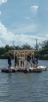
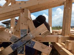
- Cooperative floating space construction | Full-scale tectonics | Jun, 2020

- 2022 Robot Aied Creation and Construction
| Digital frabrication | Jun, 2022 - july, 2022
- Student Association of Architecture Department
| Leader of speech department | 2019 - 2021
Taipei, Taiwan
For me, architecture is constantly switching between rationality and sensibility. Emotional associations create the poetry of space. Rational practice makes architecture real. The process of back and forth review makes architecture fascinating.

02 03 04 05 co-working space Design Architecture Department Design Residentail Space Design - DAILY RECORDING - INTERLACE FOREST - The Development of BIM | Revit API Sustainability Evaluation for Early Design The DIgital Forestation by Human Robot Collaboration Collaboration between 2D drawings and 3D models BETWEEN LAYES URBAN HOMORNY FLIMMAKER'S HOME INTERDISCIPLINARY 01 00 INTERWAVES PROTOTYPE Community Center Design Before the architectural design
FORWORDS
-Constitution
Architecture not only provides space, but also becomes a carrier of different things and conveys different information. I try to present the architecture think in the form of artwork / implementation.


00
Architectural
Meteria / Tectonic / Spirit / Realization / PROTOTYPE Plaster / Concret / Wax / Wooden Structure
Before
Design
- Meterial
The material most intuitively conveys the elements of the space, and breaks through the limit of the material itself, so that the building can create spirituality.
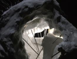

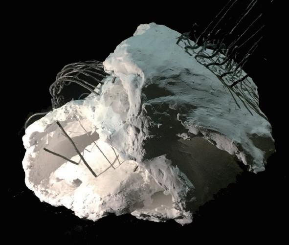
Plaster/Stripes SURMOUNT
- Tectonic
When different materials come into contact, the connected components becomes a framework that supports the whole, showingthe relationship between the materials.

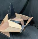

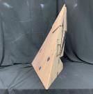
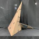
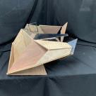
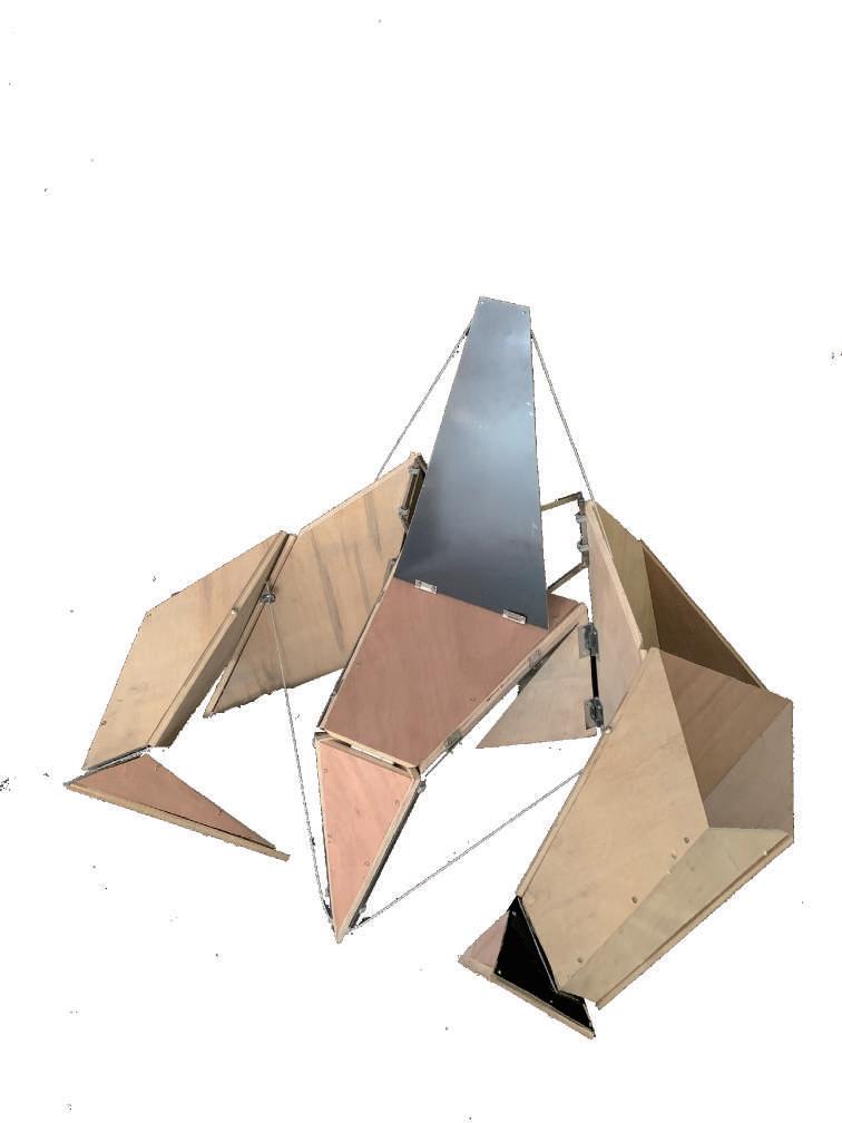
INTERACT WITH NATURE
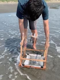
wooden construction / dropper / canvas
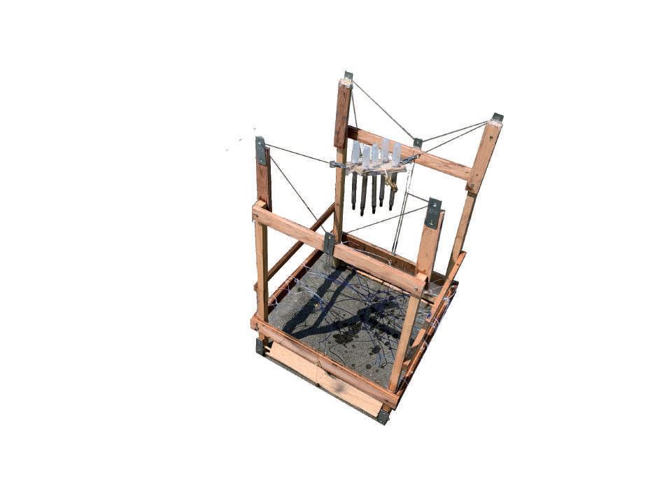
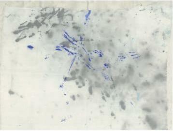
fig 1.1 When water hits the board, it would shock the dropper on the top, ink dropping on the canvas.
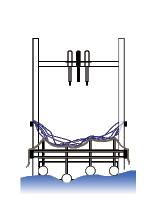
fig 1.2 When sea rised tide, buoyant force would make the canvas touch the paintstained thread.
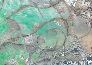
- Translation
Through the design of the installation and the interaction with nature, various traces are recorded on the canvas, and in random, charming patterns are found, formed the notation of architecture.
FIG 1.1 FIG 1.2 FIG 1.3 fig 1.3 the translation form the recordingAfter the abstract concept has been interpreted by study in space and the organizational system , we need to realize it. And the process become part of the life of architecture.
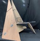
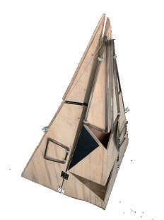
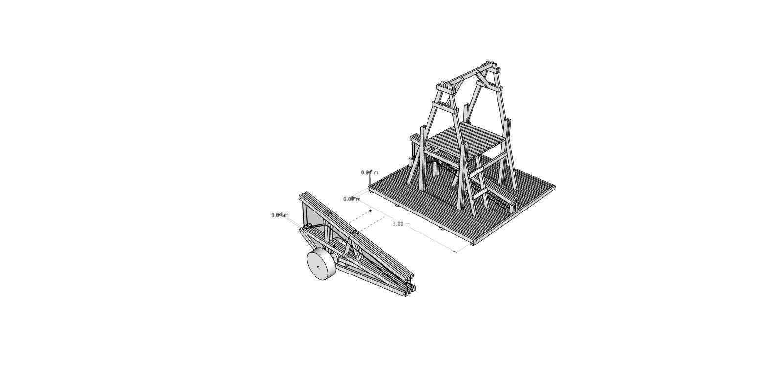
WATER SEESAW
Full - scale of wooden structure


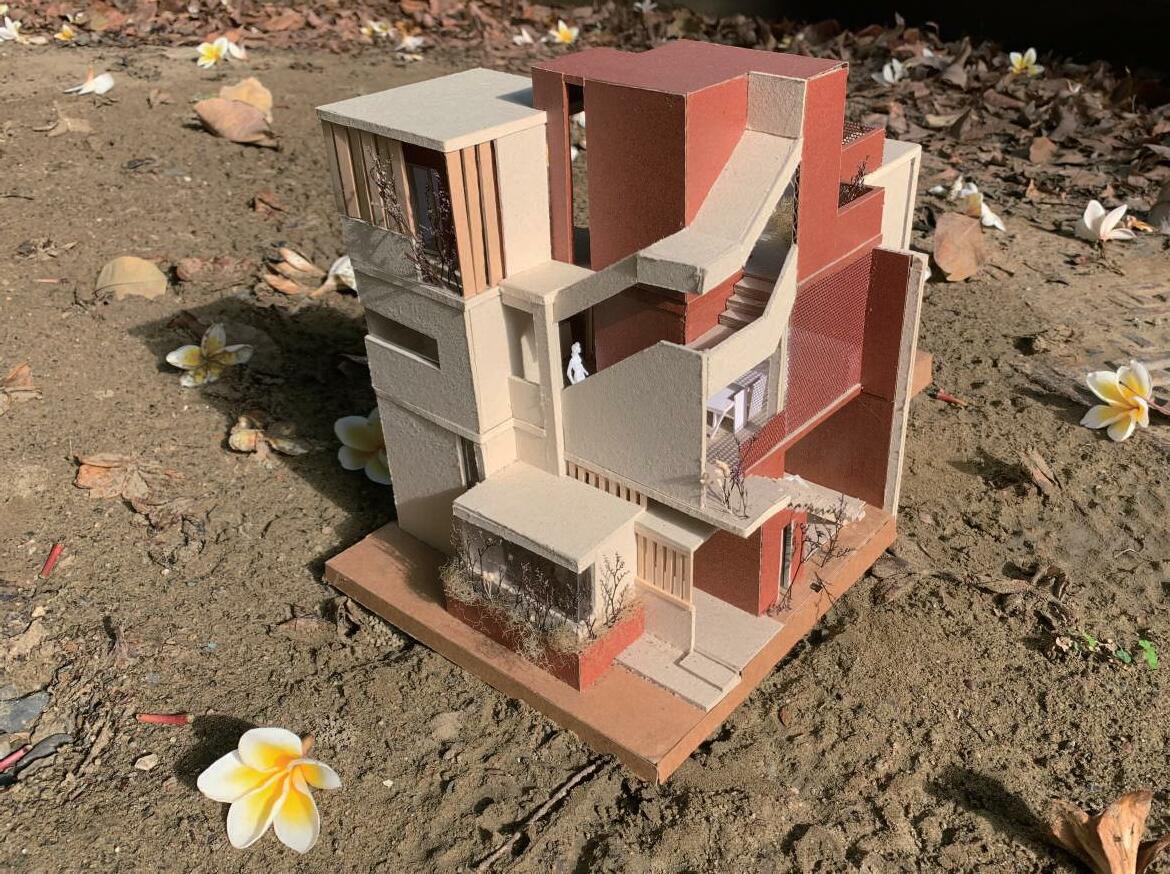
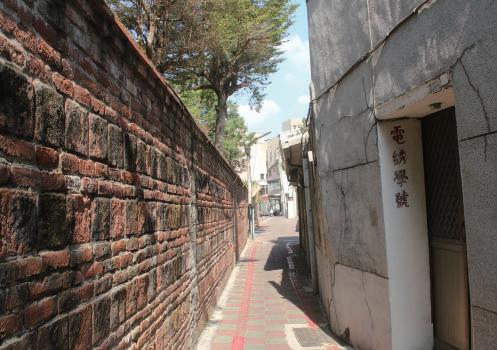
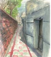
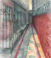
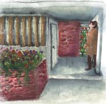
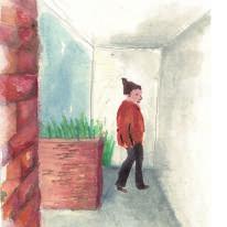
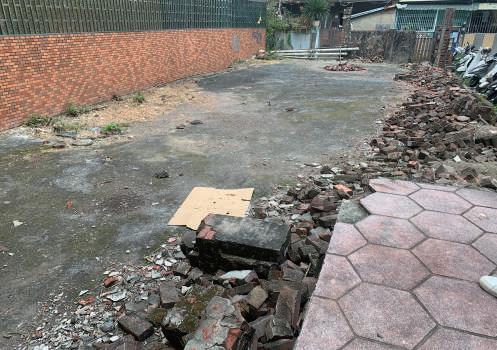
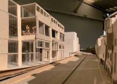
FILMMAKER'S HOME
- Extracted elements near the site
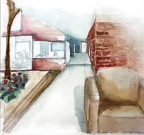
Wandering in the alleys near the site, the brick wall of Wu family garden provide a stable interface. I extracted this element in my residentail design. Taking the brick as cinestrip, it constantly intertwined with other meterias and recorded the life scene as movie.
01
Meteria / Rhythm in Spatial / Sense of place Residential Space Design
The Wu Family Garden, Tainan City
- Stable,Unstable

By capturing the elements on the site and transforming them into the rhythm of the house, the brick wall is used as a continuous and stable material in the house to bring out the surrounding environment.
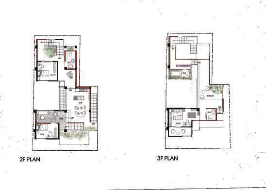
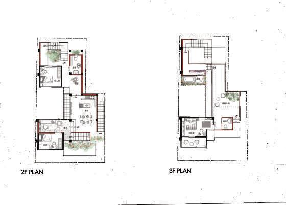
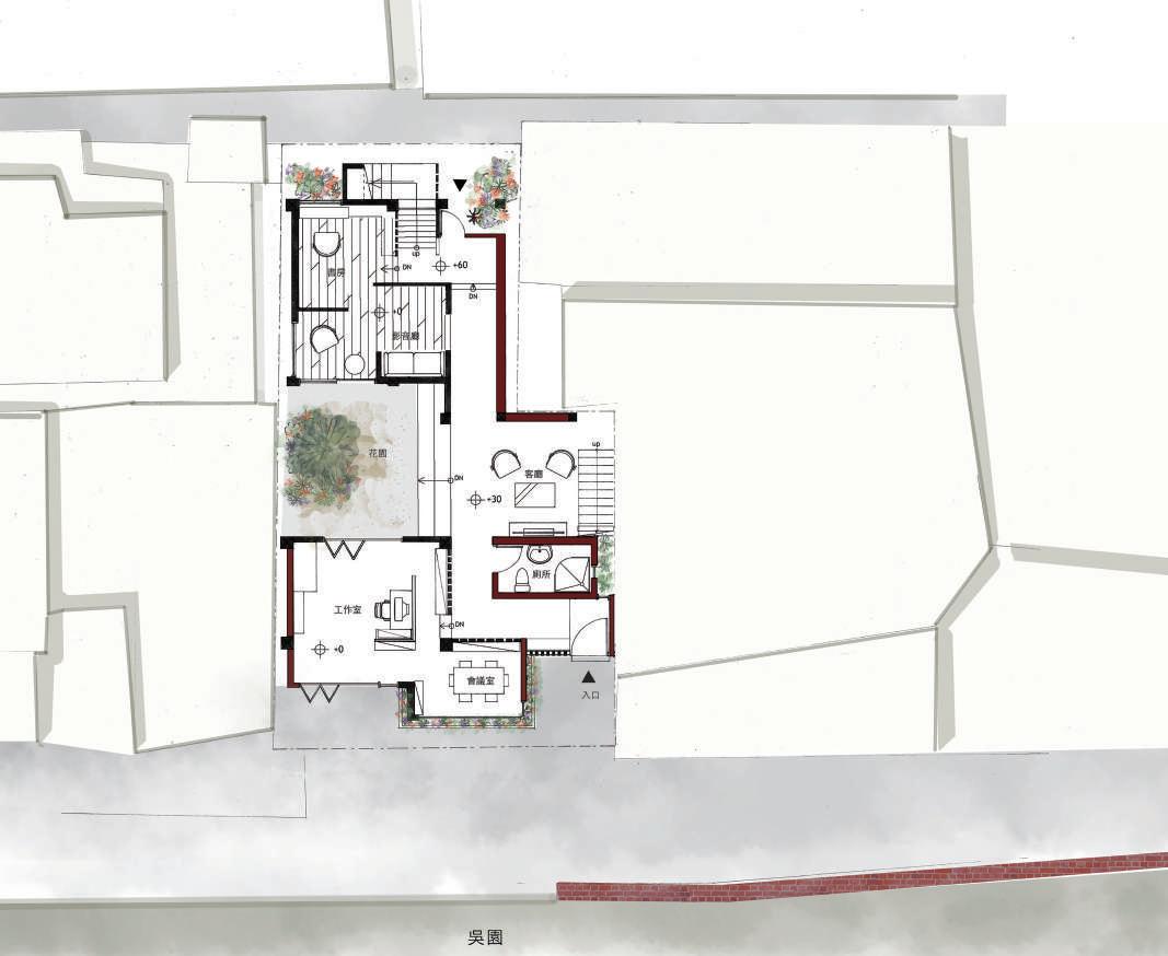
- Continuous interface, recording life
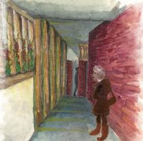
While bringing the material and sequence into the house, it also connects it with life. The studio interacting with the street, the plants enter the house, and the static open-air bath, recording life by space and material.
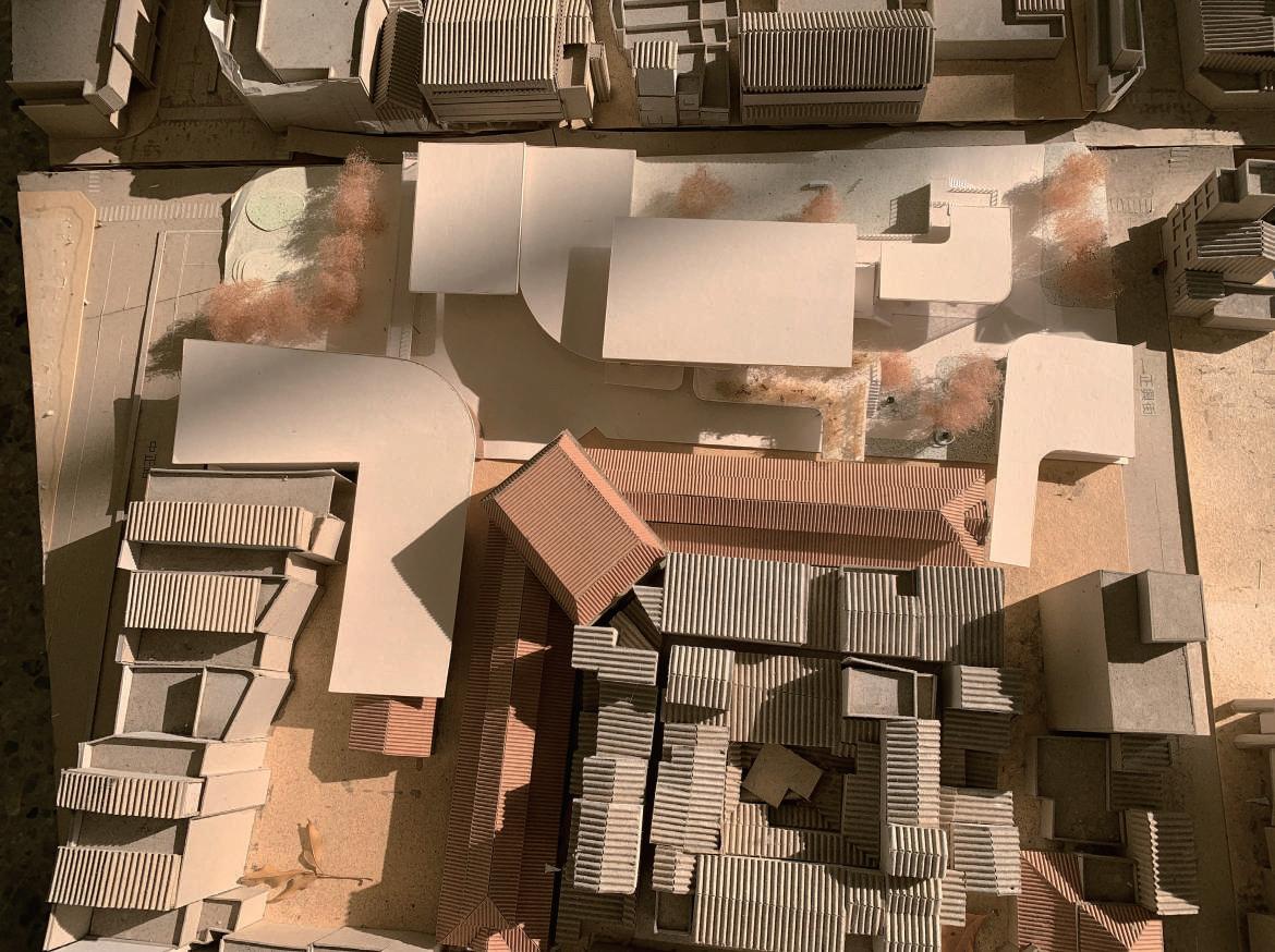
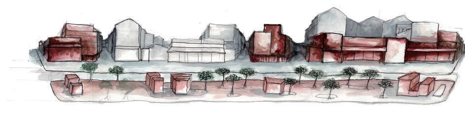
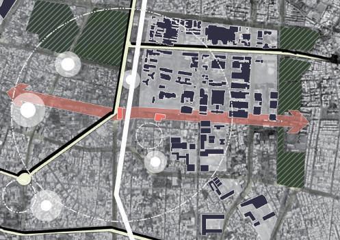
INTERWAVES
-Contradictions in the context of history
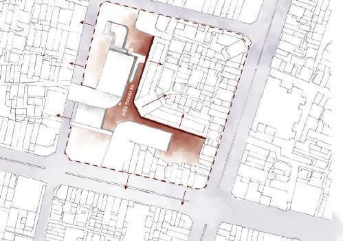
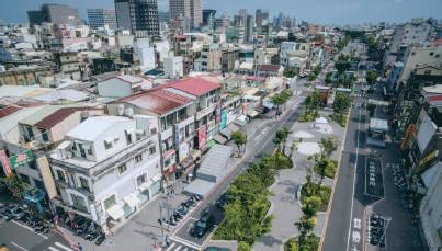
Due to the saturation of space use and the rezoning of the urban area, the commercial center shifted to other places. And neighborhood faced the site with the back side, making local Residents , Tourists and commercial spine cannot be integrated.
02
Community Center Design
Multiple Function/ Units of the Space / Urban context
Zhongzheng Rd. , Tainan City
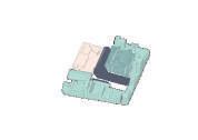
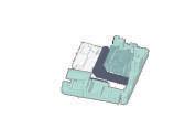
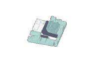
The Spatail Pattern of Fluid and Mixed Symbiosis
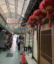
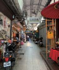
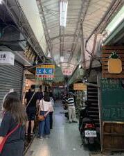
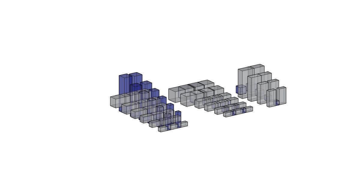
When I studied the old market in the site, I found the market has developed dynamic use of the space at different time. Due to the commercial prosperity and space saturation, the store owners overbuild to store their goods. Also, this space became their home when the market closed. I want to take this dynamic use of the space as the beginning of my design.
-
1.2
1.1
fig 1.1 photo in the west Market
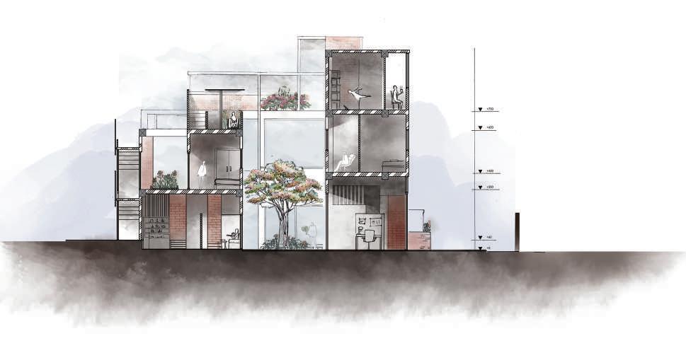
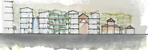
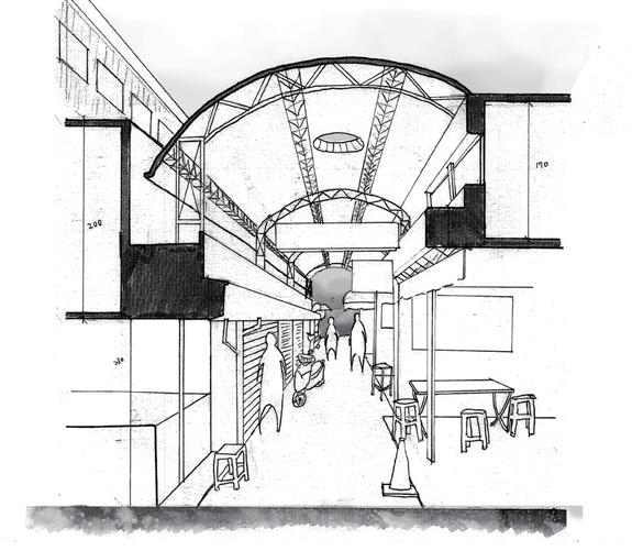
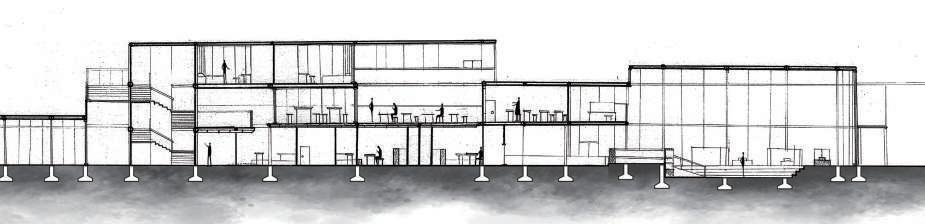
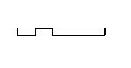
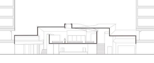
fig 1.2 section of aisle
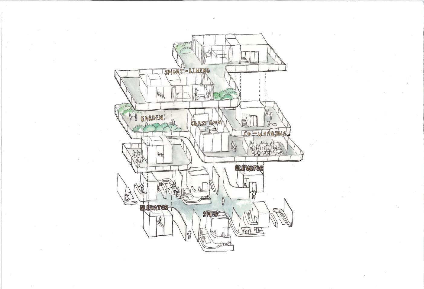
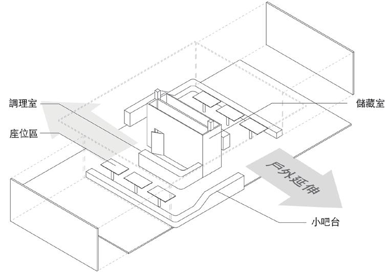
fig 1.3 diagram of function
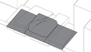
fig 1.4 vision of mixed symbiosis
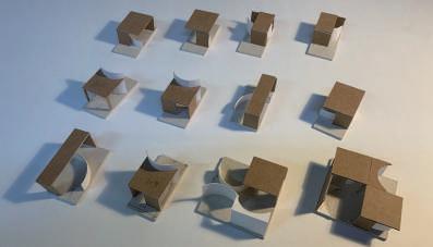
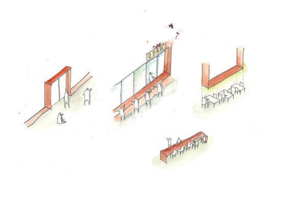
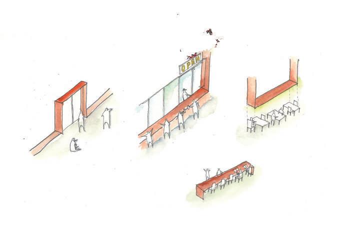
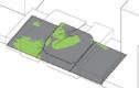
fig 1.5 units study
fig 1.6 Isometric perspective of units
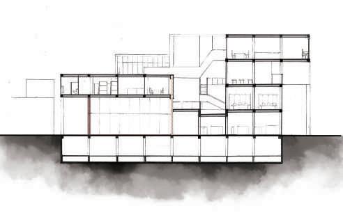
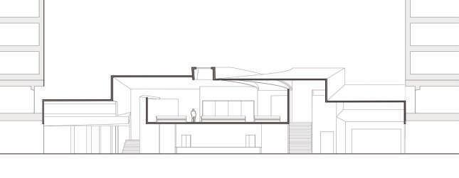
fig 1.7 C-C' section
1.4
Commercial Residentail Commercail (in history)
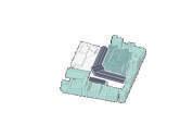
- Units Analysis
By converting the relationship of sections to small units, I analyzed the spacial feature of units. After study, I try to combine units with unique rhythm, which can be used in different functions. Moreover, the context of site can be translate into the new typology of the market space.
 1.5 1.7
1.6
Commercial space
Community classroom
Residential space Library
1.5 1.7
1.6
Commercial space
Community classroom
Residential space Library
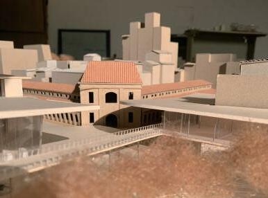
- Life, Humanities, Tourism
Through the analysis of units and combination of the flow space, the circulating space respond to the problems on the site. On a small scale, the commercial space can be integrated with the life of ordinary residents, that make the usage flexibly. On a large scale, through The banana factory covered as an exhibition and the strucrture that guide to enter the western market, the space originally belonging to the back side is transformed into a place for dialogue with history, so as to activate the whole field.
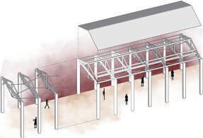
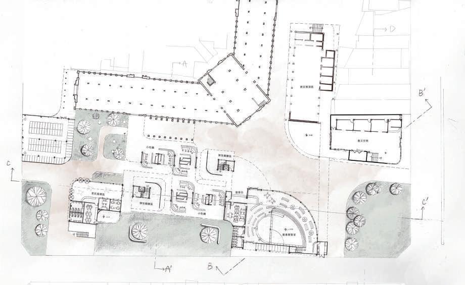
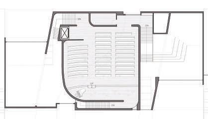
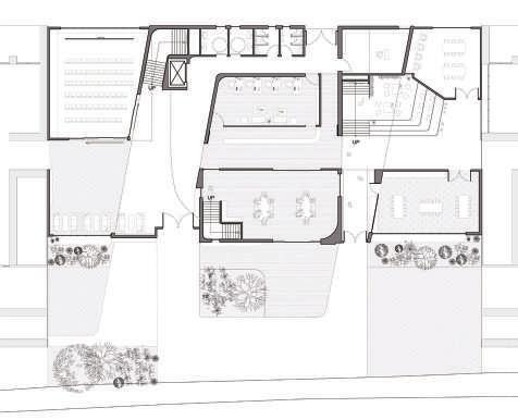
fig 1.8 GL plan fig 1.9 B-B'section fig 1.10 A-A'section fig 1.11 the guiding structure fig 1.12 commercial space perspective fig 1.13 intersection perspective 1.8 1.9 1.10 1.11
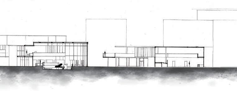
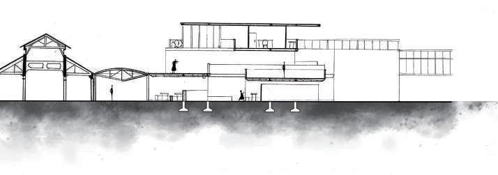
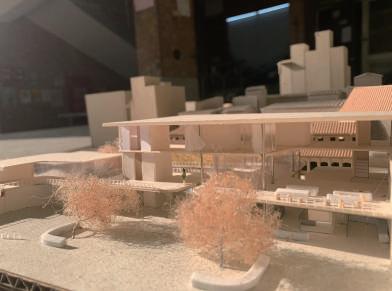


1.12 1.13 Library old market commercail space Residential space New structure between market and community center Historical museum
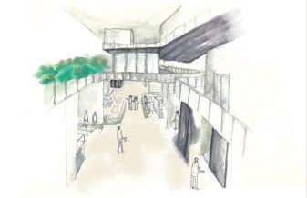
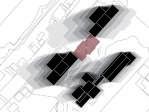
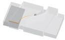
BETWEEN LAYERS
Co-working Space Design
Genius Loci / Contridition in Urban context / Design Methodology
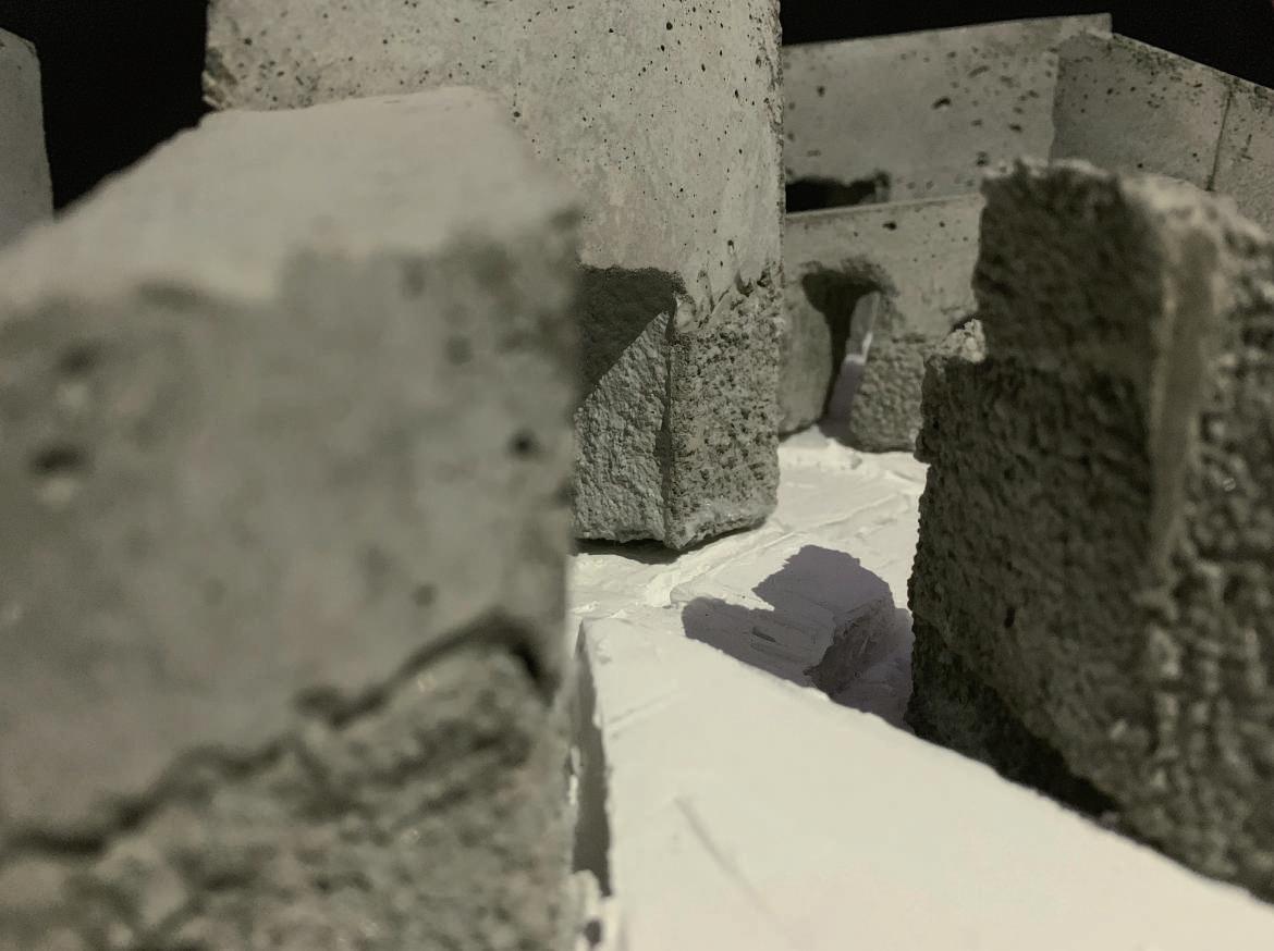
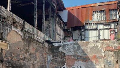
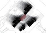
-Ruins under urban planning
The development of urban erased the history context on the site. The relics and ruins implied the ancestor's lifestyle. In my opinion, these "fourth place" still connect to the acitivity that happened before. In that case, I want to uncover these events by critical point of the view.
03
Sec.2, Hai'an Rd, Tainan City
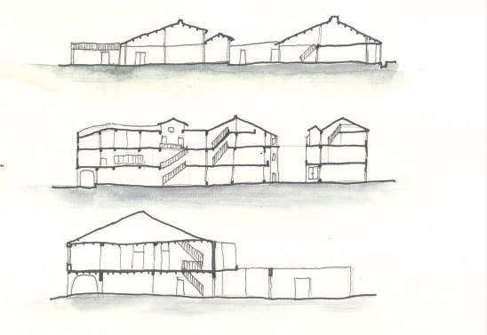
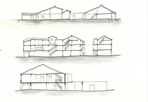
The flow of the five ports affects the direction of street houses. The spatial characteristics of Minnan style buildings have gradually evolved into the form of today's street houses with arcades. When the Hai'an road was widened, the street houses were cut open to form a deformed ground. The interior of the street house is re integrated with the urban space, as if the broken surface has been re-displayed after being covered with a layer.
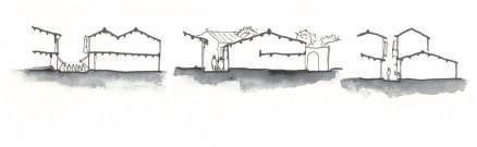

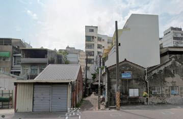
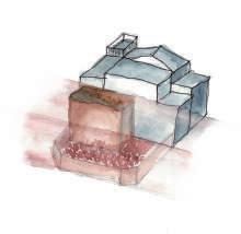
 - Fracture surface after reconstruction of Haian Road
fig 2.1 the transformation of Hai'an road
fig 2.2 Street house on Hai'an Road
fig 2.3 vision of Hai'an road
fig 2.4 the relationship between house and street .
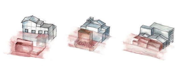
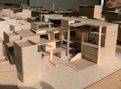
fig 2.5 study of volume overlap
fig 2.6 the volume is sperated by spatial logic
2.3
2.1
2.2
- Fracture surface after reconstruction of Haian Road
fig 2.1 the transformation of Hai'an road
fig 2.2 Street house on Hai'an Road
fig 2.3 vision of Hai'an road
fig 2.4 the relationship between house and street .
fig 2.5 study of volume overlap
fig 2.6 the volume is sperated by spatial logic
2.3
2.1
2.2
- Layers of textures are translated and reproduced.


However, the integrated space can still reflect the use of life in different eras; for the local residents, the material, size, and space configuration of the street house are used as a way to connect with the base, and it is translated into a combination of different spaces Relationship, and analyze the properties of the two spaces after the intersection, and try to combine them as the spatial logic of this design.
in 1890 Street House Type A in 1905 in 1949
2.4 2.6
MINUS X1.25
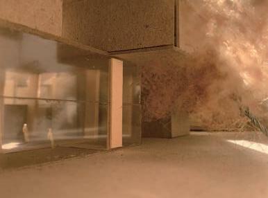
- Critical Space
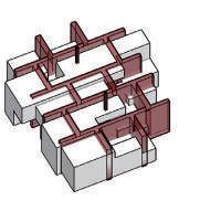
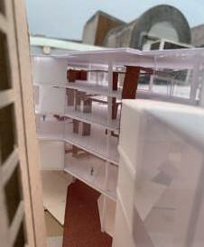
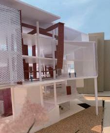
In the spatial logic,I try to respond to the historical space, and generate contradictory spatial experiences in a more radical way, such as the contrast between the facade and the internal space, not easily distinguishing the structure of columns and beams, and the use of materials implies the relationship between different levels in the site.
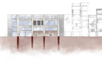
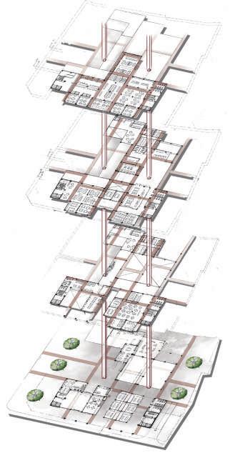
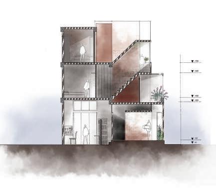
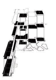
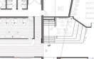
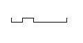
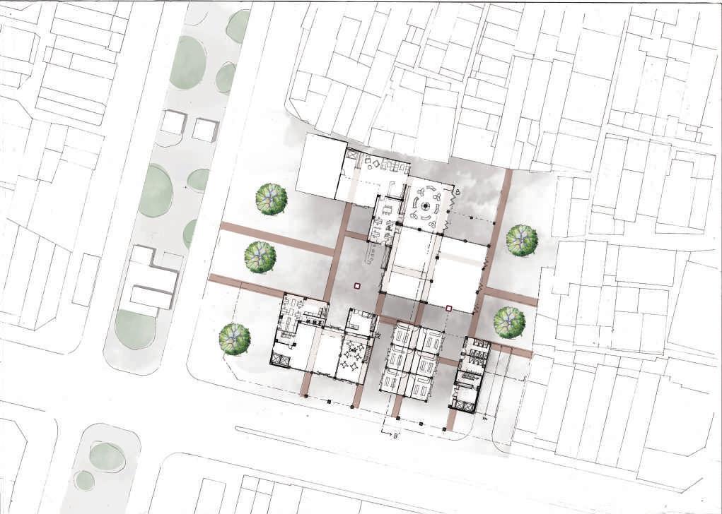 fig 2.7 the explosion fig 2.8 GL plan fig 2.9 A-A'section fig 2.10 B-B'section fig 2.11 the Elevation fig 2.12 different usage
2.7
2.8 2.11
fig 2.7 the explosion fig 2.8 GL plan fig 2.9 A-A'section fig 2.10 B-B'section fig 2.11 the Elevation fig 2.12 different usage
2.7
2.8 2.11

2.9 2.10 2.12
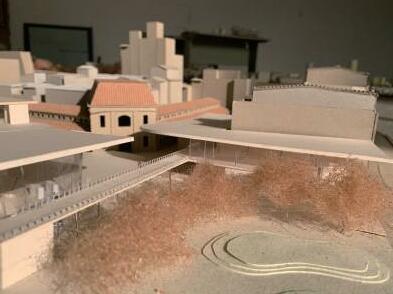
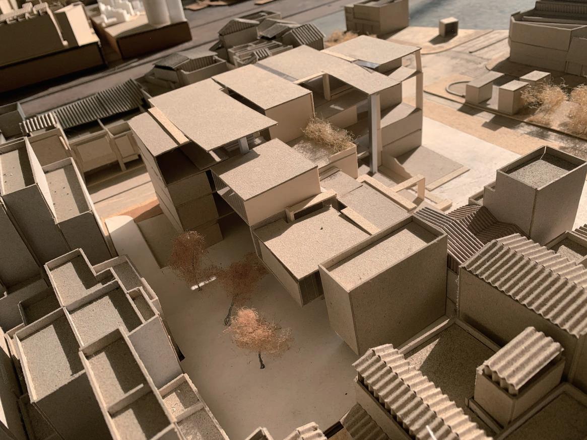
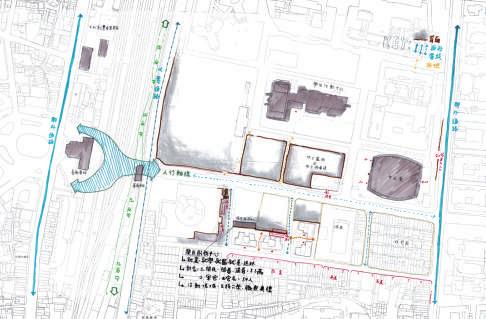
URBAN HOMONY
Architecture Department Design
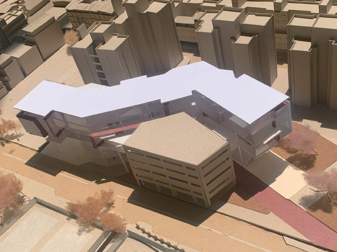
-The starting point of urban campus
The site is located in a parking lot near the campus boundary and Tainan station. Due to the urban renewal , Tainan was processing the railway Underground Project. The old railway tracks turned into a open space in urban. the land which divided by railway had opportunities to connect. " How to suture the city" is the issue that i want to discuss.
04
Blurred Campus Boundary / Figure Ground in Urban space /
University Rd., East District, Tainan City
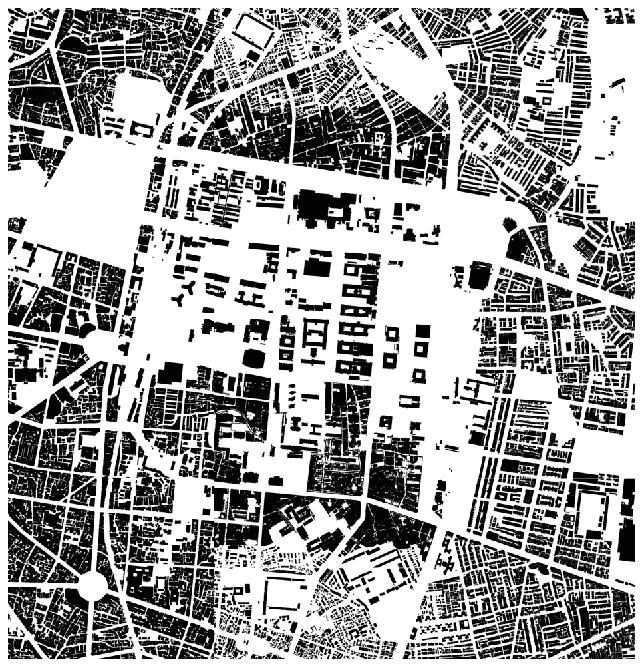
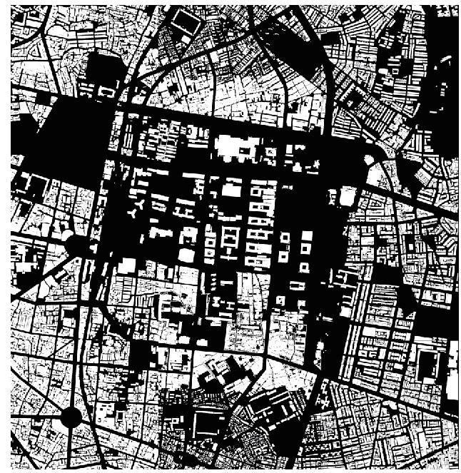
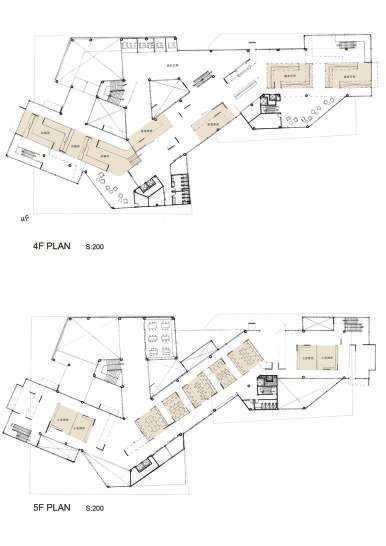
The relationship between the overall campus and the city is examined through the figure ground, and the open space on the campus is beginning to integrate with the green spaces and squares in the city, which also blurs the boundaries of the campus
- Space in architecture department

If we also look at the configuration and studio of the Department Library from the perspective of figure ground, the corridor and classroom are obviously divided, and there is no flexible space to provide students with communication and rest.
Therefore, I want to create an interface that can integrate the boundary, and at the same time adapt to different combinations of users to maximize flexibility.

GROUP GROUP GROUP GROUP GROUP STAIR GROUP
- Figure Ground
fig 3.1 Figure ground
fig 3.2 Urban planning sketch
fig 3.3 Figure ground in department
fig 3.4 Figure ground of the studio
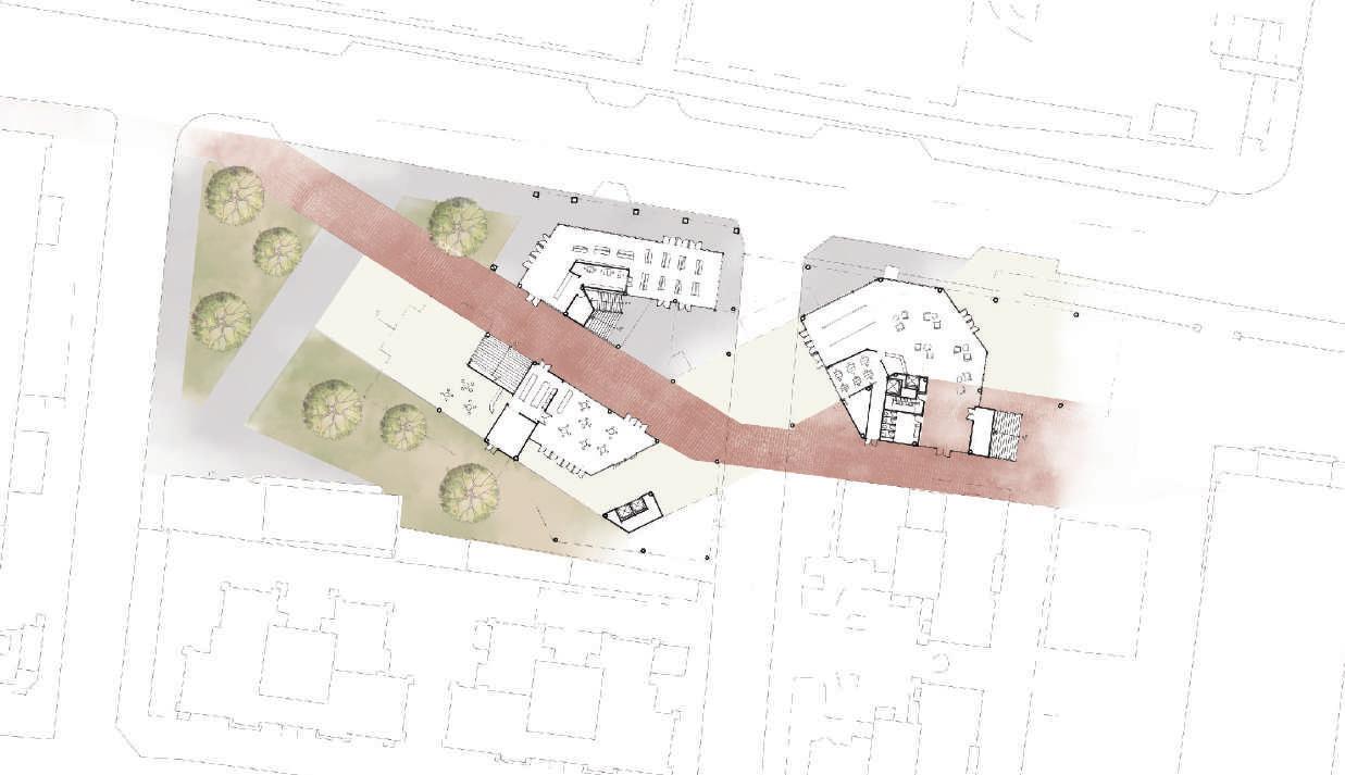
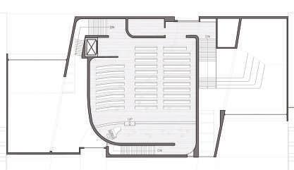
fig 3.5 Site plan
fig 3.6 Diagram of the function 3.4
3.1 3.3
3.2
- Introducing city into Department


Opening a road directly on the gl plan to organize different levels of open space, through the overall planning of the park, also attempts to introduce nature into the community space to connect different users
 3.5
3.6
3.5
3.6
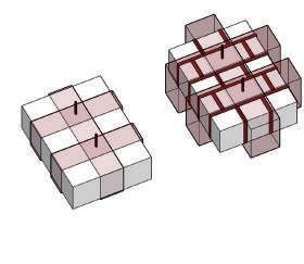
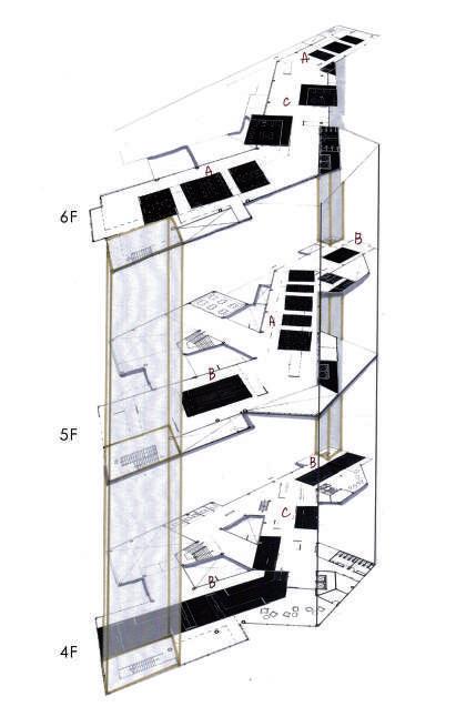
- Flexible Used Space
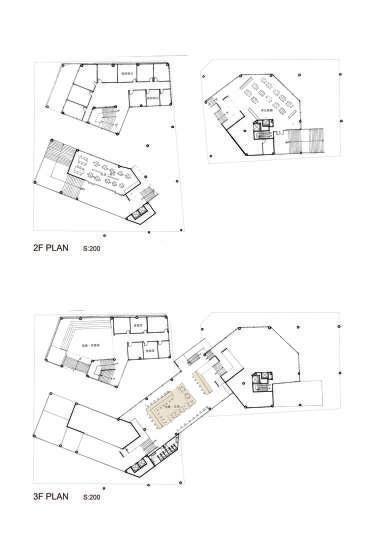
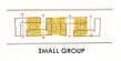
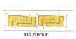
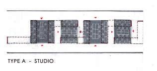
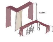
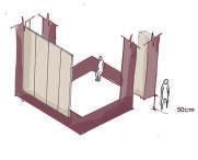

On the upper plane, three different types of combination patterns, A, B and C, are brought in, so that there can be unique rhythm in the transparent space, and units of different sizes can serve different uses.For different space, it should be adjusted according to the openness of each floor
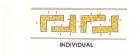
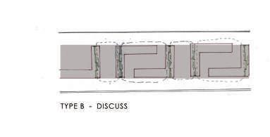
TYPE A TYPE B TYPE C
-
Blurring the Boundary Between Indoor and Outdoor
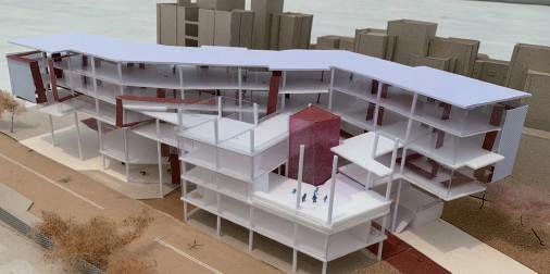
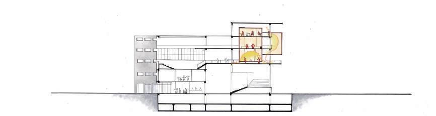
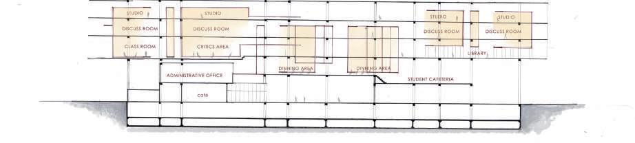
The configuration of the element makes the section produce more layers, the flow of the corridor is no longer to divide the floor horizontally, but the gap between the elements to define, to achieve the effect of fuzzy boundary.
Different Aspects of Architecture INTERDISCIPLINARYS

- Digital Fabrication
- Sustainability Evaluation for Early Design
- The Delvelopment of BIM | Revit API - Trying
For me , the way to understand architecture is to learn from many aspects and try different things. Learning the expirience form living, cooperation which is the best way to see things from a new perspective. The more open the vision is, the more I can experience different beauty.

88
05
Assembling the tree units
Robot Arm, Environment Analysis, Coding
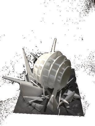
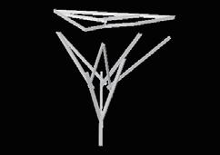
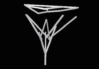
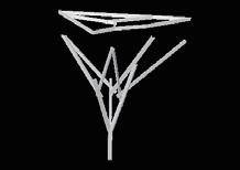
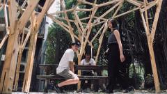
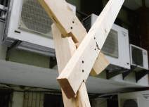
INTERLACE FOREST
The DIgital Forestation by Human Robot Collaboration
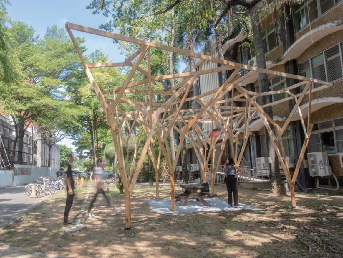
This design discusses and practices the digital real structure assisted by the robot arm, and integrates the links of design, manufacturing, and construction to form an integrated process.
The goal of this design is to build a fullscale wooden pavilion. The practical means are divided into two stages.The initial training is parametric thinking and design, and the later stage is the implementation of digital fabrication. Finally, a full-scale wooden structure is completed.
Under the framework of parametric design, information from design to manufacturing can be integrated through the use of BIM model software, and the integration process from design to robotic arm assembly can be realized.

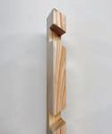
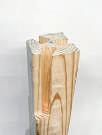
COMPOSITION
Roof 2x4 inch. lumber
The branching columns blend into the environment, and the fact they converge at the foundation also makes the pavilion easier to construct.
3rd Level 2x4 inch. lumber
2nd Level 2x4 inch. lumber
1st Level 4x4 inch. lumber
In this pavilion there are 4 layers of branches, and the 1st member section is the widest as trunk.
In this pavilion there are 4 layers of branches, and the 1st member section is the widest as trunk
62
1:1 Wood Pavilion STUDIO GOAL Parametric thinking & Design Practical verification of digital fabrication >> >> Construction Design >> Fabrication >> Construction Process integration
| Composition | | Volume & Tree-form | | Smart Digital Construction with Robot
50 51 FORM GENERATING Volume Tree-like form Branch growing direction 1 2 3 Tree Branch L - System Tree Crown Voronoi System Co umn Roof System makes the pavilion easier to construct. Area of Void 50 51 FORM GENERATING Volume Tree-like orm Branch growing direction 1 2 3 L - System Voronoi System Co umn Roof System The branching co umns blend into the environment, and the fact they converge at the oundation a so makes the pavilion easier to construct. Volume & Tree-form COMPUTATIONAL DESIGN 3D Model Vision >> Automation In Construction Contains a great deal of fabrication information BIM MODEL FABRICATION In the design process, we can use parameterization to intergrate the information.
|
process, we eliminate the members over the length range the robots linear axis also make sure they are enough to be holded by the
Constraints
parameter process, we eliminate the members over the length range the robots linear axis also make sure they are enough to be holded by the
In the parameter process, we need to eliminate the members that are over the length range decided by the robots linear axis area, and also make sure they are long enough to be holded by the fixture.
Milling cutter
Milling cutter
Roof
Milling cutter which is round shaped & flat end, makes we need to fillet the joint corner, and let the acute angle become more than 90°.
Milling cutter which is round shaped & flat end, makes we need to fillet the joint corner, and let the acute angle become more than 90°.
65 Working area Constraints 250cm > L > 60cm Member length Linear axis 420cm Fixture space 60cm parameter
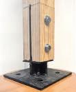
4X4 lumber
Ø12mm bolt
8mm steel plate
Ø15mm bolt hollow brick concrete
We connect the timber column and concrete foundation with steel plate, and correct the horizon by adjusting the bolts.
Milling cutter which is round shaped & flat end, makes we need to fillet the joint corner, and let the
become more than
Composition
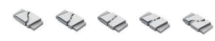
The roof unit is composed with a frame and inter connection. The frame contains multiangle and different numbers of members gathering at one joint. We have 5 types of joints including connection and extension.
The three members inside the frame are connected by three butt joints to keep them at same level.
5° 5° 5° 5° 5° 5° B C D E A 65 Working area
Bottom - Middle Middle - Top Tenon
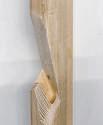
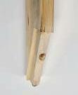
Generating rule
We shift the b-member by 20cm along the a-member direction, and then move 12cm upward with c-member. The three members are lapped.
In order to automate assembling with robotic arm, the tenon's bottom section is smaller than the top, so that it has the tolerance and it can auto-correct the position by sliding the member in.
https://issuu.com/yixuanlee/docs/rac-coon_rats_20220818
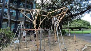
When assembling the lumbers, we need to put them one by one with the order to make sure that they are on the right positions.

65 FABRICATION CONSTRAINTS Working area
250cm > L > 60cm Member length Linear axis 420cm Fixture space 60cm 1
55mm 12mm Size Fillet No acute angle >12mm(13mm) R>6mm (7mm) >90° _ <55mm 2
angle
90°. 65 FABRICATION CONSTRAINTS Working area Constraints 250cm > L > 60cm Member length Linear axis 420cm Fixture space 60cm
acute
55mm 12mm Size Fillet No acute angle >12mm(13mm) R>6mm (7mm) >90° <55mm 2
Process
Foundation
Process
b b b c c c
First member
Process
74 5° 5° 5° 5° 5° 5° 5° 5° 5°
b b c Internal connection Frame
We rotate the three members 5° clockwise to stagger the connection between each member, thus we generate a triangular joint in result.
250cm > L > 60cm Member length Linear axis 420cm Fixture space 60cm 1
Generating rule
Constraints
Milling cutter 55mm 12mm Size Fillet No acute angle >12mm(13mm) R>6mm (7mm) >90° _ <55mm 2
In the parameter process, we need to eliminate the members that are over the length range decided by the robots linear axis area, and also make sure they are long enough to be holded by the fixture.
Milling cutter 55mm 12mm Size Fillet No acute angle >12mm(13mm) R>6mm (7mm) >90° _ <55mm 2
Milling cutter which is round shaped & flat end, makes we need to fillet the joint corner, and let the acute angle become more than 90°.
Read The Full Content !
DAILY RECORDING
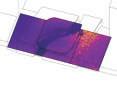
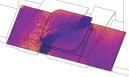
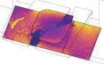
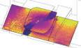
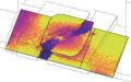
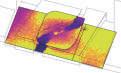
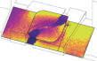
Sustainability Evaluation for Early Design

這次展出的是第一階段的設計操作,每位同學必須找到一位建築大師的設計作品,一方面運用科學分析工具對作品 進行分析,另一方面閱讀大師對於這個作品、甚至在那個時期的創作理念。同學在經過分析與評估之後,除了必須 試著在環境分析中找到改良大師作品的機會,改善的建築手法更必須符合大師的設計概念。
這個建築設計的操作,嘗試將室內環境品質(建築物理)、建築耗能(綠建築),以及近代建築史的課程結合在一起。過 程有別於同學過去以主觀性、感受性,以及案例分析式的學習,將同學帶到客觀性、理性,以及系統分析式的操作 手法。我認為建築設計的教學,無論是理性或是感性的論述,都該是腳踏實地、實事求是的。
The main purpose of the first stage is to learn the operation and application of software, and to combine analysis, evaluation and design concepts; while the second stage is to teach with the industry, try to apply the whole system to practical design, and find new possibilities in the process.

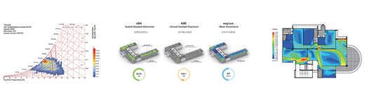
在分析與評估的操作當中,同學們對許多建築物理相關基礎理論的應用會更加理解。比方說將氣象資料運用Govini 的Bio-Climatic Chart使用了PMV model在空氣線圖上呈現,可以協助設計做出初步的判斷;在CFD的氣流分析中 ,了解RANS model分析平均風速的特性,因此必須慎選時間區段來進行分析。期盼未來同學將這些分析工具與理 論帶到業界,讓建築師們可以看得懂、實論述。過程中很開心看到同學努力閱讀大量的文獻、學習軟體操作的技巧 ,也要特別感謝過程中碩士班的王致堯同學擔任助教,你辛苦了 。
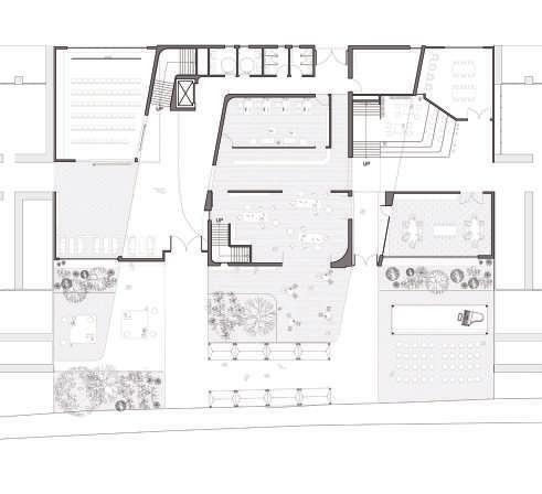
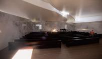
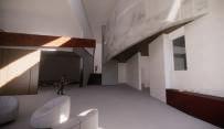
In the design of the combination of the nursing center and the church, we hope that the light can play different roles in the space. The light in the church, like time, enters through different openings, and also guides people's work and rest in the day. The appearance of light also constantly changes between daily and sacred. The preparation room with flexible function has a different atmosphere between the week and the weekend. We also hope that the identities of the elderly, believers and caregivers can continue to rotate.
指導教授 | 蔡耀賢 傅政文 Casa Barragan 黃子祐 馬賽公寓 楊詠琪 Church of the Three Crosses 張雅評 Salk Institute 權唯一 Darwin D. Martin House 展場簡介 展場作品配置
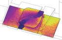
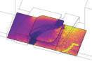
0 1 2 5 A 1F PLAN 2F Sanctuary Ancillary space, Nursing care space 1F Daily Sunlight Exposure 8 AM - 16 PM Direct Skylight Jan - Dec ) > 300 LUX AVG > 1000 LUX DIR 0 1 2 5 A-A’SECTION NURSING HOME CHURCH Residential Space Gathering Space THE CHURCH OF DAILY RECORDING LIGHT The morning light that spills over the dining table in the living room D A L Y B E L E F The character of Light in space ELDERS、BELIEVEIRS NURSE AIDE、CLERGY The character of user in space Rays of God and sublime |Weekdays| |ACTIVITY| |CONCEPT|
12:30 -16:30 PM CHURCH Youth Fellowship Lunch Break Prayer Meeting Sunday Worship Social Activities & & & & LEFT SIDE SKYLIGHT NURSING HOME Outdoor Activities Afternoon Tea Family Time Workout 9:30 AM 12:30 PM 16:30 PM 9 30 12:30 12 : 30 - 16:30 1F PLAN 左側天 將人從入口 Jan. 11 hrs 0 hrs Shadow covered Hours Jun. Daylight Accumulate d Hours N 40 cm 70 cm 100 cm Window Size Degrees of Rotation TYPE A TYPE B TYPE C A-45 B-45 A-15 B-15 C-15 A-0 B-0 C-0 A+15 B+15 C+15 A+45 B+45 C+45 C-45 0° Clockwise 15 ° Clockwise 45 ° Counterclockwise 15 ° Counterclockwise 45 °
|WEEKDAYS| |WEEKENDS|
Theater
Performance Venue
Viewers: Family members
Performer: Elders
Sanctuary Church RIGHT SIDE SKYLIGHT CENTRAL SKYLIGHT
Viewers: Elders believer
9 30 - 12:30 2F PLAN


中央天井 由祭壇引道 至 另 側樓梯
RIGHT SIDE SKYLIGHT CENTRAL SKYLIGHT RIGHT SIDE SKYLIGHT
6 30 8:30 將人從入口引導至樓梯 14 : 30 15 : 30
右側天窗
Proposal 4 –administrative 禮拜準備室 彈性活動空間 1F PLAN
6 : 30 AM 7 : 30 AM 8 : 30 AM
9 : 30 AM 10 : 30 AM 11 : 30 AM 13 : 30 PM 14 : 30 PM 15 : 30 PM 16 : 30 PM
9 : 30 AM 10 : 30 AM 11 : 30 AM 12 : 30 PM 800 Lux 0 Lux
9 : 30 AM 10 : 30 AM 11 : 30 AM 12 : 30 PM 800 Lux 0 Lux
9 : 30 AM 10 : 30 AM 11 : 30 AM 12 : 30 PM 800 Lux 0 Lux
9 : 30 AM 10 : 30 AM 11 : 30 AM 13 : 30 PM 14 : 30 PM 15 : 30 PM 16 : 30 PM
A’ 2F PLAN B B’ A 1 A-A’SECTION 0 A-A’SECTION 2 5 1F PLAN B B’ B B’ A A’ A’
’SECTION
1 2 5 B-B
Performer: Clergy |Weekends| 9:30 -12:30 AM 6:30 -12:30 AM
The Development of BIM | Revit API
Collaboration between 2D drawings and 3D models by Revit API

Research Purpose and Implementation Process
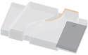
The construction industry mainly uses 3D models to assist in more accurate valuation and formwork calculations when estimating and planning formwork areas. In that case, the architect offices increases the need to transpose 3D models on 2D drawings during the communiation. However, due to the difference in data types between the two in software use, the conversion is time-consuming and inefficient; this research proposes the use of Revit API-based , to integrate the difference in data structure between the two to achieve high efficiency and high precision; the research results are divided into two stages to display, the first stage is the analysis and application of DWG file types; the second stage is the rapid production of 3D models; Finally, a workflow is proposed to achieve practical application.
PHASE 1 : DWG Document Type Analysis and Application
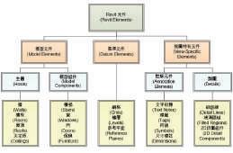
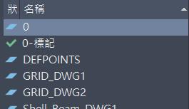
In Revit, AutoCAD files can be imported in two ways: import and link; since the AutoCAD database is set up for managing "lines", its main contents are points, line coordinates, styles, and display text. The Revit database is classified according to various types of objects, including the basic information, quantity and content of a certain type of objects, which can be customized according to needs. When analyzing through the API, due to the difference in data conversion, there are two methods; one is to read geometric information (points, lines, surfaces, volumes...), and the other is to read non-geometric information (text, label blocks...) reading; since the plain text information cannot be obtained in the API, it is necessary to use the DWG reading database provided by the Open Design Alliance platform for crawling.
 FIG 2. DWG file analysis platform
FIG 1. After the data is read, it will be presented in a table
FIG 2. DWG file analysis platform
FIG 1. After the data is read, it will be presented in a table
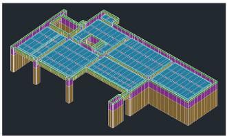
PHASE 2: Rapid Production of 3D Models
DWG 檔案內的檔案資料後,再將取得的資訊轉換為 BIM 軟體內的物件
模型,由於文字資訊是透過外部抓取,因此在建模的同時,對於”資料配對”的
方式變得格外重要,以下嘗試以種案例時,實踐 DWG 檔案到 3D 建模的實例;
第一段是透過抓取 DWG 檔案的線段轉換牆的元件,以應用到版本差異上變化模

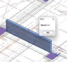
After successfully capturing the file data in the DWG file, the obtained information is converted into an object model in the BIM software. Since the text information is captured externally, the method of "data matching" becomes very important. When trying to use the following case, practice the example of DWG file to 3D modeling; The first section converts the wall components by grabbing the line segment of the DWG file to display the model difference; the second section reads the door and window opening labels, finds the corresponding opening information through the position search method, and displays them in the wall components.
型差異的顯示;第二段為讀取門窗開口標籤後,透過位置搜尋的方式找到相對應 的開口資訊並在牆的元件上新增開口。

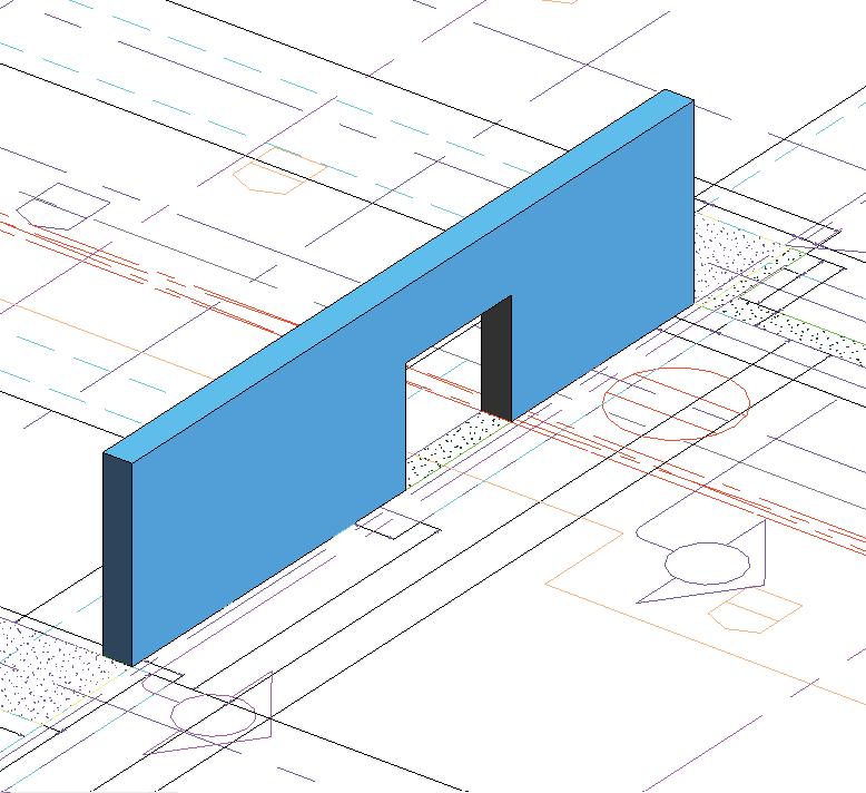
Redraw line
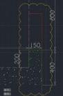
Select the line that creates the wall
Define the type of wall through geometric operations
read text information Create openings Change display color To easily identify version differences
Workflow for Practical Applications

綜合以上研究成果的應用,提出現階段半自動化的工作流
AutoCAD 圖面比較之功能,將有版本落差的 線級抓取出來,並連結進 BIM 軟體中,而後在 Revit 內抓 取比較的圖層結果並透過 API 快速產置 3D 模型,並將導 出的模型做進一步的應用,如計算出不同版本間模板數量
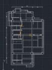

Based on the application of the above research results, a semiautomated workflow is proposed at this stage. First, through the function of AutoCAD drawing comparison, the line level with version gaps is captured, and linked into the BIM software, and then captured and compared in Revit 3D model can be quickly generated through the API, and the exported model can be further applied, such as calculating the difference in the number of templates between different versions and re-evaluating.
PART 2
現階段 WORK FLOW 預想(半自動化開發)
STEP 1
Through the function of AutoCAD drawing comparison, the line level with version difference is captured and linked into the BIM software.
STEP 2
STEP 3
Apply the exported model further, for example: calculate the difference of data between different versions, and make further valuation.
Check the Complete Process!
-Template estimation
- area calculation
- engineering valuation
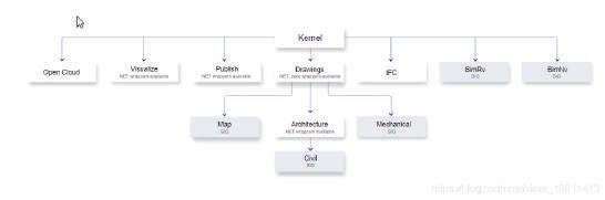
FIG 3. Version difference comparison FIG 4. programming logic1 - 現階段專案方向與目前已開發之軟體與應用
PART 0 PART
Grab the compared layer results in Revit and quickly generate 3D models through the API.
2: 3D模型快速產製
實務應用的工作流程
CODE看實作影片! 版本差異模型建置 掃描QR CODE看實作影片! 文字讀取後的開口應用
的差異與重新評估。Fig .7 實作工作流程 Fig 6. 模型建立 Fig .4 版本差異比較
寫邏輯
Fig 5.程式撰
Grab the line level inside the DWG file
https://youtu.be/YP4TVV38yMQ
FIG 5. Implementation Workflow
FU,CHENG-WEN
cola42015@gmail.com (+886)915115007