

PORTFOLIO

Select Projects 2019 - 2024
Fu, Cheng-Wen
Bachelor of Architecture, National Cheng Kung University

THE CONCEPT OF FOLDING
“ New Narratives for Complex Environments ”
At the intersection of technology and design, we are witnessing an unprecedented era of innovation. As a designer and researcher, I observe technology evolving beyond its traditional role as a tool, becoming an active co-creator. This shift represents not just technological advancement but a revolution in thinking and practice.
This portfolio documents my exploration of the dynamic relationship between technology and design. The works are categorized into two core dimensions: “Design Based on Technology” and “Technology Based on Design”. Each dimension examines how technology can transcend its function as a mere replicative mechanism to become a strategic force driving cultural and industrial development.
“The concept of folding” stems from my graduation design as a way of thinking about our complex contemporary environment. In this era of rapid technological development, perhaps we should adopt a method of extracting and folding to find connections between different fields. This will provide us with an open and flexible perspective to reexamine our environment.

Design Based on Technology
01 Interlace Forest
Human-Robot Collaboration in Digital Tectonics
02 Daily Recording
Light Simulation-Driven Church Design
Technology Based on Design
03 Building Embodied Carbon Calculator
Sustainability Evaluation Tool for the Early Design Phase
04 Streamlining Sensor Registration and Updating Process in BIM - Based Digital Twins
Data Visualization Platform for Digital Twin Integration
05 BBQ, Boundless Book Quill
AI - Assisted Collaborative Picture Book Platform
Other Works
06 The Place Where Water Leaves
Revealing the Land Texture of Urban Borders
07 Appendix
Revit API Development, Parametric Design

Interlace Forest 01
Digital Tectonics Forestation by Human Robot Collaboration

Parametric Design + Robotic Fabrication
This project emphasizes the concept of “Technology-Empowered Design”
Through this approach, we explore and practice the integration of digital real-structure design assisted by robotic arms. By connecting design, manufacturing, and construction, we aim to establish a seamless and integrated workflow.
Year | 2022, Team Projects
Category | Robots Tectonics, Real Construction
Location | NCKU, Tainan City
Task Division | Parametric Design, Robot Arm Operation
Instructor | Shen, Yang-Ting Yen, Chia-Ching
Implementation Process
The goal of this design is to build a full-scale wooden pavilion. The practical means are divided into two stages.The initial training is parametric thinking and design, and the later stage is the implementation of digital fabrication. Finally, a full-scale wooden structure is completed.
We use wood as the primary construction material, applying various processing techniques such as drilling, milling, and cutting to wooden lumber. This approach aims to transform the material’s inherent constraints into design and construction challenges, ultimately paving the way for practical and innovative application methods.


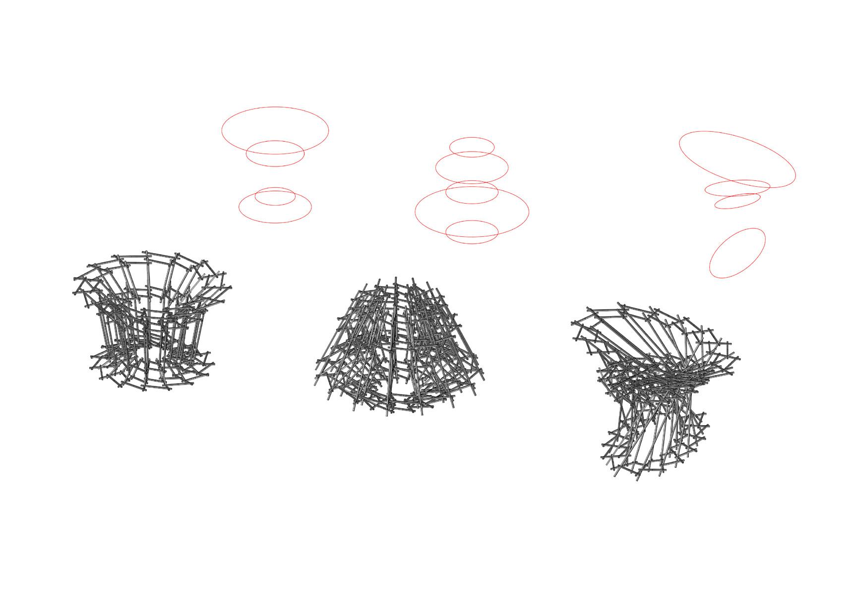
Form Generation & Parametric Design
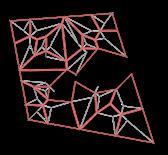
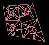
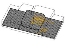
The path, trees, and historical building form the visual axes around the site. These axes define the pavilion’s shape and echo the volume of the banyan tree at the roundabout. The branching columns naturally blend into the environment, and their convergence at the foundation simplifies the construction process. The pavilion’s design consists of two parts: the supporting structure, generated using an L-system, and the roof structure, designed with a Voronoi system.
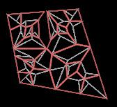
Roof Structure Optimization
The roof structure is designed using a Voronoi diagram, as it effectively distributes weight to the nearest columns. Member lengths are limited by the fabrication setup, requiring the roof frame to be carefully optimized to meet these constraints.

Shortest Member
Longest Member


Assembly System for Wooden Pavilion


Composition
Roof 2x4 inch. lumber
Top 2x4 inch. lumber
Middle 2x4 inch. lumber
Bottom 4x4 inch. lumber
In this pavilion there are 4 layers of branches, and the trunks, which are the members in the first level, have the largest cross-section area.
屋頂TYPE A
Roof, Internal Joint & External Frame
2X4 lumber 屋頂TYPE A
A 屋頂 TYPE B
屋頂 TYPE B
屋頂 TYPE B
屋頂 TYPE C
屋頂 TYPE C
TYPE
屋頂 TYPE D
屋頂 TYPE D
Outer Frame

Daily Recording
The Sustainability Evaluation for Early Design

Sacred Space Design + Environmental Simulation
This design combines a long-term care facility with a religious space. Using site-specific light simulations and parametric design, it controls light movement throughout the day, shaping the layout and enhancing comfort. Light harmonizes the care and religious functions, transitioning the sacred church into a communal living room for daily activities.
Year | 2023, Individual thesis
Category | Church, Environmental Simulation
Location | NCKU, Tainan City
Instructor | Yaw-Shyan Tsay
ElderlyCareCenter

The Character of Sunlight in Space
This design primarily serves as an elderly activity center and a place of worship for the elderly. It aims to connect the activities of the elderly and clergy through the interplay of light. Throughout the day, the role of light continuously shifts, acting as a medium to create a sense of sanctity while also fostering a sense of everyday life.
ActivityCenter&Church
ElderlyCareCenter


Parametric Simulation of Solar Trajectory
Through parametric design and the setting of three control points, simulations of different window forms and light trajectories are conducted. This process identifies design solutions that achieve appropriate lighting levels and further influences the spatial configuration.


Chapel 1F Elderly Activity Centers 3. Rotation Angle : 45° 1. Skylight : 50m x 50m 2. Height : 70 cm

2 Spatial Lighting Result


Connecting Different Users Through Sunlight
On the floor plan, spaces for the elderly and clergy are interwoven in their arrangement. Throughout the day, the trajectory of sunlight alternates, illuminating different activities, thereby enhancing opportunities for interaction between them.
From the perspective of light simulation and analysis, the design creates a comfortable indoor environment while further defining the role of light in different spaces, marking the occurrence of various activities within the space.
The Schedule of Clergy


Building Embodied Carbon Calculator
Sustainability Evaluation Tool for Low-Carbon Building Design


Sustainable Design Assessment + Integrated Workflow Proposal
The Paris Agreement’s 2050 net-zero targets prompted Taiwan to review construction emissions and introduce LEBR regulations, assessing embodied carbon in material production, construction, renovation, and demolition.
To address the lack of streamlined workflows for emissions compliance in architectural design, JJP Lab developed a carbon calculation tool tailored to Taiwanese regulations. It integrates workflows from basic to detailed design, supporting the transition to near-zero carbon sustainable architecture.

Year | 2024 , Individual Research
Category | Tool development, Python, Grasshopper, UI design
Company | JJP architects & planners
Structure

Main Structure Carbon Emission Calculation
Due to the complexity of the regulatory calculation formulas, the user interface is designed to allow project designers to simply select the design volume and input the span size, enabling automatic calculation of other necessary values. This approach provides users with real-time carbon emission feedback without requiring them to fully understand the detailed calculation formulas.


Step
1 : Select the Main Structure Material


2 : Input Default Design Parameters


Step
Design’s
Baseline’s
Building Component Carbon Emission Calculation
For building components, the calculation aligns with project designers’ modeling habits, enabling layered visualization charts for easy comparison of design schemes. It also categorizes regulatory parameters, streamlining green building certification applications.


Step 1 : Create Building Component for Calculation


Step 2 : Group the Components for Visualization


Step 3 : Using Model Layers as Visualization Groups


Classify Calculations Based on Model Layers


Classify Calculations Based on Regulations.


1. Connect to the Firm Database
2. Generate Material List
3. Create Component for Calculation
1. Group Components 2. Connect to Visualize the Result
1. Classify Layers Based on Personal Preferences
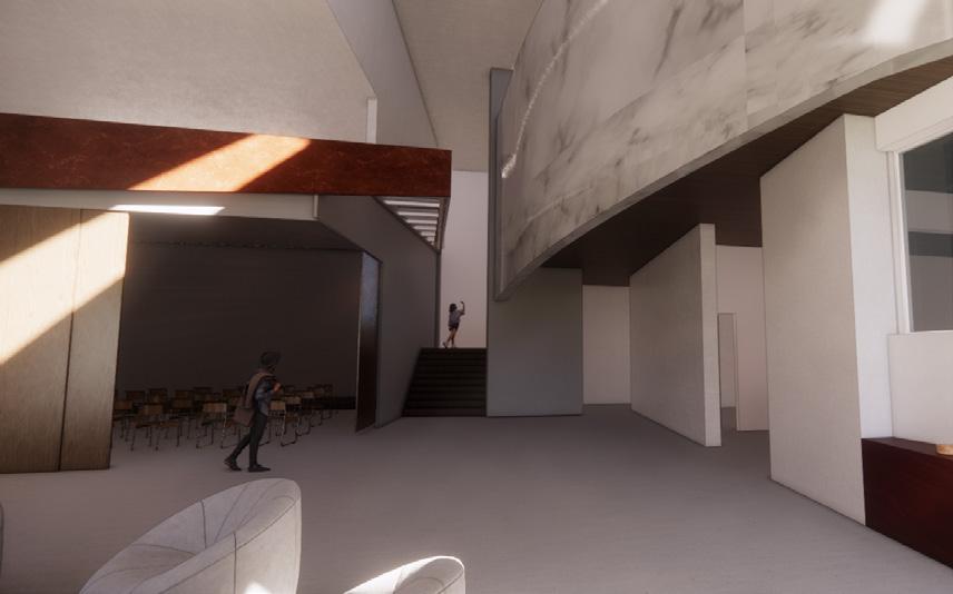
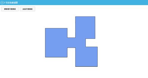
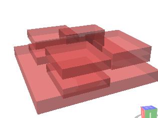
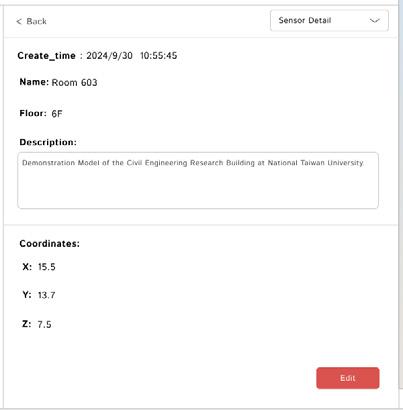
Streamlining Sensor Registration and Updating Process in BIM - Based Digital Twins
Data Visualization Platform for Digital Twin Integration

Integration Framework for DT + User-Centered Interface Design
Digital twin technology optimizes energy use, driving the transition to Net Zero Energy Buildings (NZEB). However, high costs and complexity make it challenging for facility managers to develop their own systems without skilled personnel.
Our research proposes a streamlined platform using Autodesk Platform Services (APS) and Building Information Modeling (BIM). It simplifies digital twin creation by integrating sensors, spatial management, energy data, and updates, with a user-friendly interface for efficient, expertise-free management.

Year | 2024 , Individual Research
Category | Digital Twin, IOT, Web Development
Instructor | Shang-Hsien Hsieh
- Proceedings of the International Conference on Civil and Building Engineering Informatics (ICCBEI), 2025.

User Interface in the Proposed Platform
three-tier Diagram


BBQ, Boundless Book Quill
Educational Platform for Collaborative Picture Book Creation

AI- Powered Refinement + Collaborative Picture Book Creation
This project introduces students to creative writing and imaginative thinking through picture book storytelling. Aimed at 4th to 6th-grade students, it encourages free creativity in the classroom.
In a 50-minute class, the teacher could hold an activity to guide students through a collaborative storytelling and sketching exercise. Students work together to create a story, deciding on its direction through class voting. Throughout the session, they sketch scenes to accompany the story, which are later refined and unified using AI, resulting in a cohesive and polished picture book. This approach fosters creativity, teamwork, and imaginative thinking in a short but impactful session.

Teacher


Activity Initiator )
Co-Creator )

User Login )


Creator - 1 )
Creator - 2 )


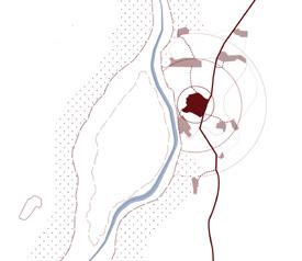
The Place Where Water Leaves
Revealing the Land Texture of Urban Borders

Redefining the Image of City : Urban and River
In the past, Nanzai Gou served as a cargo transportation waterway, while the establishment of the Lin Family Garden laid the foundation for the development of Banqiao and Fuzhou. However, with sediment accumulation and upstream river diversion, the once expansive river channel has deteriorated into an urban drainage ditch, leading to the gradual disappearance of water-related activities.

I aim to view contemporary urban development from a new perspective, redefining the relationship between cities and rivers through the establishment of four turning points. These human-scaled urban exploration routes connect existing activities within the site, revealing the land’s textures and enhancing the city’s identity.
Year | 2023
Category | Urban Design , Individual thesis
Location | Banqiao Dist., New Taipei City
Instructor | Chun-Kai Fang
- Thesis Design Award, NCKU Department of Architect
- Merit Award, New Taipei City Architects Association
- Select Award, Taipei City Architects Association


The function of transportation was replaced by trains.
Major transport route aiding Banqiao City's establishment
Major transport route aiding Banqiao City's establishment
Major transport route aiding Banqiao City's establishment
Banqiao
Fuzhou
Revealing Land Textures Through Folding
Confronting the four historical boundaries between the city and water, I have created four designs that span across them, each serving as a turning point to reconnect the city's and water's shared memories. This pathway also links various activities within the current site, transforming the area from an urban periphery into a place that gathers people, fosters activity, and reveals the textures of the land.


Guanyin Mountain


Crossing & Riverside Park
& Observation Deck
Community and Campus Boundary


DWG
檔案內的檔案資料後,再將取得的資訊轉換為 BIM 軟體內的物件
模型,由於文字資訊是透過外部抓取,因此在建模的同時,對於”資料配對”的
方式變得格外重要,以下嘗試以種案例時,實踐 DWG 檔案到 3D 建模的實例;
第一段是透過抓取 DWG 檔案的線段轉換牆的元件,以應用到版本差異上變化模
型差異的顯示;第二段為讀取門窗開口標籤後,透過位置搜尋的方式找到相對應
的開口資訊並在牆的元件上新增開口。
版本差異模型建置

CODE看實作影片!
實務應用的工作流程

版本差異比較

綜合以上研究成果的應用,提出現階段半自動化的工作流
AutoCAD 圖面比較之功能,將有版本落差的
線級抓取出來,並連結進 BIM 軟體中,而後在 Revit 內抓
取比較的圖層結果並透過 API 快速產置 3D 模型,並將導 出的模型做進一步的應用,如計算出不同版本間模板數量
的差異與重新評估。

文字讀取後的開口應用


Define the type of
through geometric operations
read text information Create openings
Change display color To easily identify version differences


Fig 6. 模型建立
Fig .4
Fig 5.程式撰
Grab the line level inside the DWG file
Redraw line Select the line that creates the wall
wall