Before installing, please ensure you have downloaded the latest version of this installation guide by scanning this code.
INSTALLATION GUIDE
VERSION 1.0 | 2023/06/06
1. Introduction
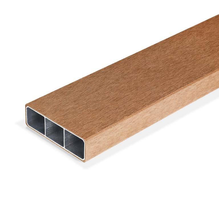
Thank you for choosing Lifespan products. This guide aims to provide information needed to successfully install the Lifespan product range. It is assumed, however, that the installer has a reasonable understanding of pergola (or similar) structures and the related building codes. Compliance with the requirements captured herein must be met for warranty coverage.
Please refer to the Lifespan Technical Data Sheet (TDS) for pertinent information for this product. The Lifespan products are available in the Eva-tech material technology cap, please also see the applicable TDS for information specific to this material.
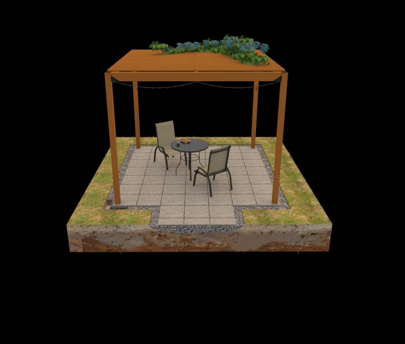


3. Critical installation points
3.1 Lifespan specific guidelines
3.1.1 Safety guideline
• Always wear appropriate Personal Protective Equipment (PPE) for the various activities involved in installing the Lifespan products.
• Take care when handling cut beams that may have burrs, sharp or rough edges.
• When storing beams, a pallet or flat surface should be used to support the beam’s full length. Do not position the product in an upright position.
• Avoid over-stacking and/or eccentric stacking.
• Ensure that the Lifespan beam is suitably clamped before cutting. Failure to do so may result in the Lifespan beam moving resulting in a poor cut, damage to equipment, or personal injury.
• Its best practice to use a sacrificial offcut or wood block between the clamp and Lifespan beam. This will distribute the clamping load which prevents collapsing of the aluminium skeleton, as well as marring of the composite cap.
3.1.2 Cutting
• Do not use grinders, chainsaws, or similar and avoid cutting with a hand saw.
• Use an appropriate aluminium cutting chip saw blade. (see Section 5.1 for more details)
• The using of incorrect blades or excessive pressure during cutting may result in cracking, delamination, or other deformation of the composite cap or aluminium skeleton.
• Do not allow the blade to exceed 60°C when cutting the Lifespan beams.
• Set the blade to cut through the beam in one pass. The blade should stick past the bottom edge by no more than 1 cm.
• Support the ends of the Lifespan beam so that it remains perpendicular to the cutting blade.
• It is advised not to rip the Lifespan beams.
3.1.3
Drilling
• It is recommended to use a drill press when drilling through both sides of the lifespan beam.
• Drilling through both sides of the Lifespan beam may result in burs in the hole on the opposite side.
• If a drill press is not available or burs do occur, mark the hole location on either side and then drill from either side of the Lifespan beam.
• Use a marking punch to create an indent into the aluminium skeleton before drilling.
• Adequately secure the Lifespan beam before drilling.
• Drill holes using incremental drill sizes appropriate to the thickness of the material been drilled into.
• Set the drill speed to a moderate speed.
• Avoid applying excessive pressure to the beam during drilling, as this may bend the aluminium skeleton or overheat the drill bit, which may cause damage to the composite cap.
3.1.4
Fastening
• Fasteners should be sized appropriately to match the strength requirements of the system, as specified by a suitably trained professional.
• Since the Lifespan beam makes use of an aluminium skeleton, particular care should be taken to specify the fastener’s material to avoid galvanic corrosion. For example, stainless steel fasteners.
• Additional strength and rigidity can be obtained by using longer fasteners such that they pierce two of the internal webs.
• Ensure that there is sufficient edge clearance to avoid tear-out of the fastener.
• Appropriate fasteners include Hulk Fasteners Z-point clip screws, blind rivets, and bolts.
• It is advised not to use nails to fasten Lifespan beams.
3.1.5 Sanding
• Some scratches and stains may be removed through sanding of the composite cap. If the stain or scratch is not deep, then sanding may remove the mark.
• The sanding motion should be along the length of the Lifespan beam.
• Light pressure should be used while sanding.
• Sanding the cap does remove cap material and should be avoided where possible.
3.1.6
Lubricants
• Avoid using lubricants as the composite cap can be stained. If a lubricant is necessary, consult the chemical compatibility chart in the Technical Datasheet and test the effect of the lubricant on an offcut of a Lifespan beam.
3.1.7
Glues and Sealants
• If glues or sealants is used, protect the surrounding composite cap using masking tape or a similar tape from staining. Remove the tape as soon as possible after application. Ensure that the tape will not leave a residence on the beam.
3.2 General considerations
• Site preparation: Prepare the installation site properly by clearing the area of any obstacles, debris, or vegetation. Level the ground if necessary and ensure proper drainage to avoid water pooling around the pergola.
• Foundation or anchoring: Depending on the design and local requirements, determine the appropriate foundation or anchoring method. This may involve pouring concrete footings with embedded posts, or using anchor brackets on existing slabs, or attaching the pergola to an existing structure. Ensure the chosen method provides stability and meets any applicable building codes. For installations on top of new footings, allow the concrete to dry before completing the rest of the pergola installation. This may require that you dig holes and pour footings a few days or more prior to assembling the pergola depending upon the concrete used and climate.
• Beam and post alignment: Ensure the beams and posts are aligned correctly during installation. Use a level to ensure that the pergola is plumb and square, preventing any potential leaning or instability. Accurate alignment will also contribute to the overall aesthetic appeal of the structure.
• Connectors and fasteners: Utilize proper connectors and fasteners recommended. Follow the provided instructions carefully to ensure secure connections between beams, posts, and any additional components. Use appropriate hardware, such as stainless-steel screws or bolts, to resist corrosion and maintain structural integrity.
• Load distribution: Consider the weight and load distribution on the pergola. Ensure that the load is evenly distributed across the beams and posts to prevent any excessive stress on individual components. This is particularly important when adding features like hanging plants or lighting fixtures.
• Roofing installation: If your pergola includes a roof or canopy, follow the manufacturer’s instructions for proper installation. Ensure the roofing material is securely attached and provides adequate protection from the elements. Consider the need for additional supports or reinforcement for the roof structure, depending on the weight and type of roofing material.
• Electrical considerations: If you plan to install electrical wiring, lighting, or other electrical components within or around the pergola, consult with a licensed electrician to ensure compliance with local electrical codes. Install all electrical components safely and follow proper wiring practices to avoid any potential hazards. The cavity of the Lifespan beams may be used to hide wiring.
• Safety measures: Install safety measures, such as adding end caps or covers to exposed beam ends, to minimize the risk of injury from sharp edges. Consider any potential hazards, such as low-hanging fixtures, and ensure adequate clearance for safe movement around the pergola.
• Finishing and maintenance: Regularly inspect and maintain the pergola, addressing any issues promptly to prolong its lifespan and ensure continued safety.
4. Pre-installation
4.1 Standards
Legislation may differ between jurisdictions. Before installing any Eva-Last product, ensure that the application is rational and complies with the local regulations and building codes. Wherever necessary, consult a suitably qualified professional. Be sure to comply with material manufacturer specifications. Where manufacturer’s specifications and building codes differ, revert to the building code requirements. Check that your choice of product is suitable for its intended application. For further product specification and information visit www.eva-last.com
4.2 Safety
Always wear appropriate Personal Protective Equipment (PPE) for the various activities involved in installing the Lifespan products. This includes, but is not limited to, equipment such as safety glasses, helmets, gloves and boots, masks when cutting or similar, and harness systems when working at heights or similar, as dictated by applicable occupational health and safety legislation.
Refer to the applicable Material Safety Data Sheet (MSDS) for additional information. Please do not hesitate to contact Eva-Last should you require any additional assistance.
In addition, when working with composite materials, it is advisable to:
• Collect, store and/or dispose of off-cuts, dust and/or contaminated materials appropriately.
• Collect sawdust and similar by making use of drop sheets or vacuum attachments.
• Clean up sawdust and similar by vacuuming or wetting and sweeping (avoid sweeping dry as this can further disperse dust particles).
• Work in well-ventilated areas.
• Take care when handling cut beams that may have burrs, sharp or rough edges.
4.3 Storage and handling
Note the following:
• Ensure to comply with the local occupational health and safety legislation when lifting and handling boards.
• When handling lengths of beams greater than 4 m, ensure both ends are lifted simultaneously and evenly. Hold the beams approximately 1 m from each end to provide better control.
• Handle the Lifespan beams carefully. Dropping the beam (and all impact loads in general) can result in damage.
• During transportation use corner protectors where strapping is required.
• All components should be stored completely under cover.
• When storing Lifespan beams, a pallet or flat surface should be used to support the beam’s full length. Do not position Lifespan beams in an upright position.
• All components should be securely stored.
• No component should sit in water or similar.
• Avoid over-stacking and/or eccentric stacking.
• Take care when lifting, placing onto, or removing from raised pallets. Beams may be bundled for convenience. More than person may be required for lifting depending on the length and number of beams. Ensure mass handled does not exceed safe limits as defined by applicable local legislation.
4.4 Site and application assessment
Below are aspects typically considered with the application of Lifespan products:
• Consult an appropriately qualified professional whenever necessary.
• Assess the site and its environment:
• Ensure the bearing capacity of the structure and/or substrate below the installation is suitable for the anticipated loads. Differential settlement can impact the distribution of loads and consequently the performance of the system.
• Ensure appropriate surface and subsurface drainage around the installation footprint to avoid any negative impact on the installation. Prevent erosion or similar in and around the project footprint.
• Ensure the corrosion resistance of the installation is suitable for the site’s corrosion category and the installation’s design life. It is recommended to prevent moisture ingress into the cavities of the beams. Alternatively, allow for suitable drainage and, when necessary, additional protective coatings or maintenance. This is particularly important when running services within the cavities of the beams Appropriate connections and fasteners should be selected to avoid creating a galvanic corrosion environment with the aluminium skeleton of the Lifespan beams. Gaskets, or similar, may be useful to assist with the control of moisture. o Consider current and potential future seasonal temperature changes and make allowances where necessary within the connections, by adjusting beam spans, and/or material choice.
• Attempt to consider any micro environmental aspects of the site that may impact the design of the system, and the installation or maintenance thereof. This can include considerations such as the presence of insects, plants, or microorganisms that may impact the cap or cavities of the Lifespan product range.
• Assess the product in relation to the site and the application:
• Ensure the beam’s sizes, orientations, frequencies, layouts, and spans employed are suitable for the anticipated loading throughout the project’s design life. Loads generated during construction, maintenance or cleaning, access (if applicable), the addition of services, as the environment changes (the growth of creeping or hanging plants, as an example), or from wind, seismic activity, rain, snow, etc. should be considered if necessary.
• Ensure the connections and fasteners employed are appropriate.
• Develop a maintenance plan to ensure the longevity of the system. This should consider aspects such as moisture control, corrosion prevention, accessibility and cleaning, plant and pest control, services access, etc. With respect to corrosion prevention, it is advisable to ensure that any exposed metals are coated whilst accessible. In areas of high corrosion classes, add additional protective coats and proactive maintenance is recommended.
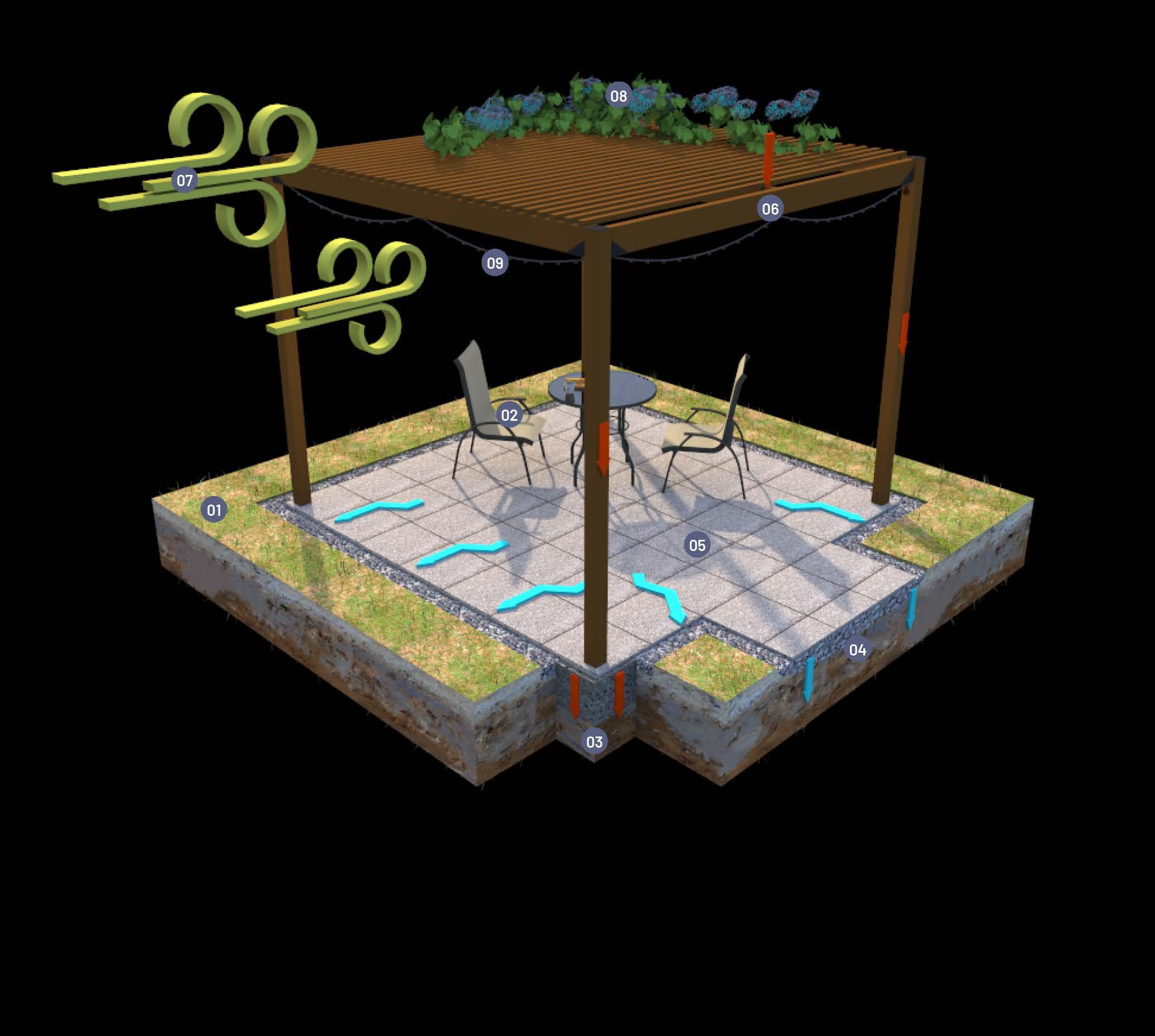
4. Assess the surface and sub-surface drainage conditions of the site. Plan for erosion if necessary.
5. Consider the path of sun and the impact of surrounding structures on this.
6. Assess the beam type, layout, loads and spans thereof.
7. Consider environmental impacts such as wind, hail, snow, seismic activity, etc.
8. Consider impacts as a result of plants, canopies, covers, etc. and the potential evolution of these overtime.
9. Consider the use of services and the installation, management, access, etc. thereof.
5. Lifespan Beam Processing
5.1 Cutting
5.1.1 Safety guidelines
• Ensure that appropriate PPE and safety precautions are adhered to. Ensure that the correct harnesses and additional safety equipment in used when working from elevated heights.
• Ensure that the Lifespan beam is suitably clamped before cutting. Failure to do so may result in the Lifespan beam moving resulting in a poor cut, damage to equipment, or personal injury.
• Its best practice to use a sacrificial offcut or wood block between the clamp and the Lifespan beam. This will distribute the clamping load which prevents collapsing of the aluminium skeleton and marring of the composite cap.
5.1.2 General notes
• Lifespan beams are provided as factory cut; ends should be trimmed where necessary.
• The Lifespan beams can be mitred.
• Use light pressure during cutting. Excessive pressure during cutting may also result in localised deformation of the aluminium skeleton.
• Do not use grinders, chainsaws, or similar.
• Avoid cutting with hand saws.
• The use of incorrect blades and high pressure may result in cracking, delamination, or other deformation of the composite cap and aluminium skeleton.
5.1.3 Cross-cutting
• Use an aluminium cutting chip saw blade, with the following specifications:
• Fine-toothed blade (48 to 54 teeth or minimum of 10 TPI) – higher is better.
• Carbide-tipped, non-ferrous material.
• Diameter of 150 to 165 mm. Larger diameters require a slower rotational speed.
• 1.5 to 2.1 tooth kerf – thinner is better.
• Minimize heat build-up with a triple-chip or alternate top bevel (ATB) tooth configuration.


5.2 Drilling
• It is recommended to use a drill press, if required to drill through both sides of the Lifespan beam.
• Drilling through both sides of the Lifespan beam may result in burs in the hole on the opposite side.
• If a drill press is not available or burs do occur, mark the hole location on either side and then drill from either side of the Lifespan beam.
• Mark then punch the required hole location. The punch should easily pass through the composite cap and indent the aluminium skeleton.
• Adequately secure the Lifespan beam before drilling.
• It is recommended to use a drill with the following specifications:
• High speed steel or cobalt material
• 118° drill point angle will reduce grabbing.
• General purpose drill shape with two flutes that is suitable for aluminium.
• Do not cut more than 6 mm at a time. Plan incremental drill sizes appropriately. For example, if a 15 mm hole is needed, then drill a diameter 6 mm hole, then a diameter 12 mm, and lastly a diameter 15 mm hole.
• Set the drill speed to a moderate speed.
• Use light pressure until the composite cap is passed and the aluminium is reached. Slowly increase to medium pressure. High pressure may bend the aluminium skeleton or overheat the drill bit, which may cause damage to the composite cap.
• Avoid using lubricants as the composite cap may be stained. If a lubricant is necessary, consult the chemical compatibility chart in the Technical Datasheet and test the effect of the lubricant on an offcut of a Lifespan beam.
5.3 Fastening methods
5.3.1 General notes
• Fasteners should be sized appropriately to match the strength requirements of the system, as specified by a suitably trained professional.
• Since the Lifespan beam makes use of an aluminium skeleton, particular care should be taken to specify the fastener’s material to avoid galvanic corrosion. For example, stainless steel fasteners.
• Additional strength and rigidity can be obtained by useusing longer fasteners such that they pierce two of the internal webs.
• Ensure that there is sufficient edge clearance to avoid tear-out of the fastener.
5.3.2 Screw fasteners
5.3.1 General notes
This section is specific to the Z-point clip screw in the Hulk Fastener range.
1. Mark the required location of the screw.
2. Punch the mark, so as to indent the aluminium skeleton.
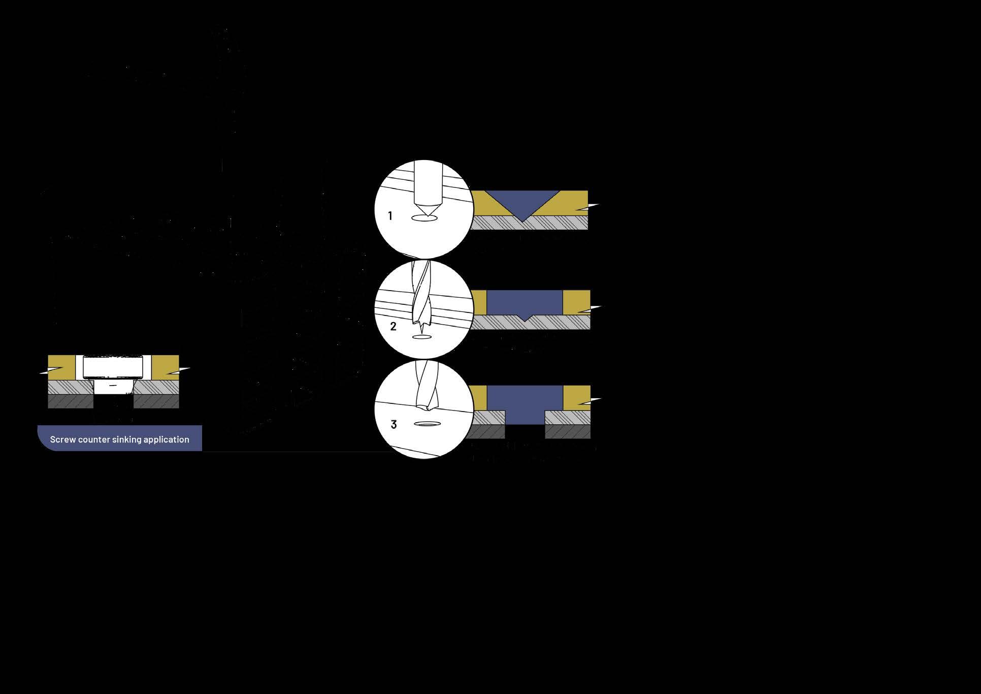
3. Use a diameter 6 mm brad-point wood drill to carefully remove the composite cap. Avoid removing the aluminium material. This will allow the screw head to sit level with the surface, giving an improved aesthetic.
4. Use a Torx T15 bit to drive the screw in.
5. Use a low speed and light pressure to allow the screw to drill through the aluminium skeleton.
6. If fixing to thin aluminium substrate, set the clutch setting to low (2 – 5) to avoid stripping the screw in the aluminium skeleton.
7. If fixing to steel substrate, pre-drill the steel with a 2 to 3 mm diameter drill bit. When driving the screw in place, set the clutch as low as possible while still being able to drive the screw. This will reduce the possibility of breaking/damaging the Torx bit.
5.3.3 Blind rivet
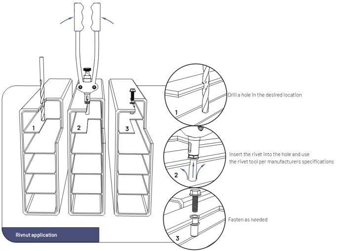
• An improved aesthetic is achievable, by removing the composite cap with a brad-point wood drill such that the blind rivet sits flush with the composite cap’s surface. The drill’s diameter should match the largest diameter of the blind rivet. Ensure that only the composite cap is removed in this process.
• Drill a hole in the desired location of the blind rivet as per the drilling section.
• The diameter should meet the blind rivet manufacturer’s guidelines.
• Screw the blind rivet onto the riveting tool.
• Insert the rivet into the hole and activate the riveting tool.
• Remove the riveting tool.
5.3.4 Through-bolt fastener
Additional shear load capacity may be obtained by using a steel tube with a suitable corrosion-resistant coating. This connection method is typically used when a beam has a post midway of its span. The quantity and size of the through-bolt should meet the loading requirements. The inner diameter of the through-bolt should be equal to 2 – 3 mm, if the Z-point clip screw is being used.
1. Mark the location of the through-bolt on either side of the beam and post.
2. On the inside face of the beam (i.e., the face against the post), drill a hole equal to the outer diameter of the through-bolt. This hole should go through all the webs but not the outer face of the Lifespan beam.
3. Repeat this hole diameter for the inside face of the post (i.e., the face of the post that is against the Lifespan beam).
4. On the outside face of the Lifespan beam, remove the composite cap as explained step 3 of the screw fastener section.
5. Repeat the process on the outside face of the post if applicable.
6. Cut the through-bolt to required length. The required length is equal to the post size minus its wall thickness, plus the beam’s width minus its wall thickness.
7. Place the through-bolt into the post and screw the fastener through the post’s outer face into the through-bolt. It may be necessary to stop the through-bolt from turning with a pliers.
8. Repeat this step for any additional through-bolts required.
9. Slide the Lifespan beam onto the installed through-bolts.
10. Check that the through-bolt’s length is correct.
11. Screw the fastener through the outside face of the Lifespan beam into the through-bolt. It may be necessary to stop the screw on the opposite side from turning.
12. Repeat this process for all remaining through-bolts.
Place the through-bolt into the post and screw the fastener through the post s outer face into the through-bolt. It may be necessary to stop the through-bolt from turning with a pliers.
1. Slide the Lifespan beam onto the installed through-bolts.
2. Check that the through-bolt s length is correct.
3. Screw the fastener through the outside face of the Lifespan beam into the through-bolt. It may be necessary to stop the screw on the opposite side from turning.
Some scratches and stains may be removed through sanding of the composite cap. For additional information refer to the applicable cleaning and care guide.
• If the stain or scratch is not deep, then sanding may remove the mark.
• The sandpaper should have a grit of 60 to 150.
• The sanding motion should be along the length of the Lifespan beam.
• Light pressure should be used while sanding.
• The sandpaper should be lifted and blown clean often to avoid clogging of the sandpaper.
6. Typical Pergola Installation
LOCATION AND MACRO ENVIRONMENTS
Bloemfontien is located on the southern edge of the South African highveld with record temperatures ranging between 40 °C and -10 °C, while falling under a typical C3 Class (moderate) atmospheric corrosion category with low salinity and only moderate pollution.
SITE ASSESSMENT OF THE MICRO ENVIRONMENT
A site assessment provided more specific details surrounding the building site and its environment.
UTILITIES
There are no utilities running across the footprint of the pergola.
EXISTING FEATURES
An existing recessed Fire pit 450 mm drop .
CUSTOMER PREFERENCES
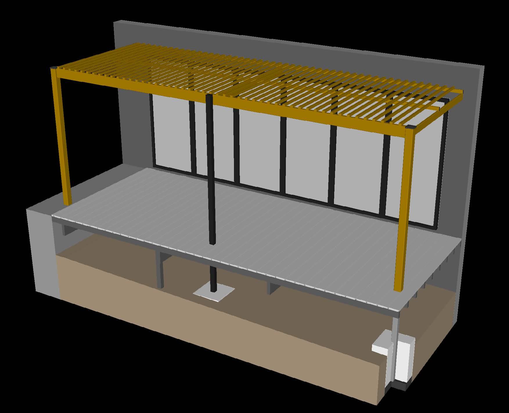
The client has specified Composite sleeved steel posts, large Lifespan bearer, small Lifespan joists and Eva-tech composite lattices spaced in order to provide shade to the attached room, in the Savanna (Tan brown) colour, with the pergola attached to the building.
PROPERTY TYPE
Residential
SUN TRACKING AND POSITION
The building is South facing and receives sunlight from early afternoon throughout the year.
ROOF ACCESS AND COVERS
The pergola's roof will be inaccessible.
PURPOSE
The pergola is required to provide additional shade cover from the sun in the afternoons.
ATTACHMENT
The pergola will be directly attached to the building and will require additional attention to door levels and drainage.
LOADS
Additional loads imposed upon the pergola structure, such as wind loads should be considered.
VEGETATION
A landscape fabric or plastic sheet should be applied beneath the floor structure of the pergola to prevent vegetative growth .
TOPOGRAPHICAL
The ground has 2° slope resulting in a 900 mm drop from the final required floor height affecting pergola post lengths.
HYDROLOGICAL
The pergola requires no further intervention as water flows away from the pergola to natural water catchment areas
PERGOLA SITE ASSESSMENT
A appropriately qualified professional has specified the structure and fastener combination to meet the environmental and loading requirements for the pergola. The footprint of the pergola must be assessed in relation to the dimensions of the required plan.
LIFESPAN DESIGN
The design life of a pergola system requires balancing the lifespans of the individual components, to the part with the lowest life span. The system life expectancy can be extended with proactive maintenance, painting, and replacing parts once the part expires.
MOUNTING TO EXISTING STRUCTURES
Ensure that the structure to which the pergola is to be attached is suitable. Alternatively mount additional posts close to the structure to create a free standing Pergola.
BEAM SPANS
Ensure that the beams are adequately supported by the posts as well as the bearers and joists.
BEAM LENGTHS
Lifespan beams typically come in 5.8 m lengths.
Optimising the design of the structure to accommodate standard lengths can save costs and beam splicing.
ACCESS AND THOROUGHFAIR
Consider post positions in regard to walk ways and access. Adjusting post positions may require the adjustment of connectors and beam sizesto suit increased spans
PERGOLA HEIGHT
POST HEIGHT
BEARER (CLEARANCE)
Ensure that the structure provides enough head clearance.
FINAL FLOOR LEVEL
GROUND LEVEL
FOUNDATION LEVEL
SUITABLE POST MOUNTING LOCATIONS
In cases where floating structures and decks are installed, The pergola posts must be installed through the structure and into or onto a suitable foundation and not directly to the deck.
UTILITIES
Before digging holes, ensure that cables and pipes are out of the way.
The post and beam positions will impact the final design of the pergola structure. The following provides a typical design layout for a pergola structure specific to the details listed for the site.
Pergola structures may require a slope away from buildings.
Lattice spans of 120 mm to provide 30% more shade to the
After finalizing the design, it is crucial to specify each junction and connection in detail. The following comprehensive list outlines the typical junctions that need to be considered for the project.
6.1.1 General notes
• The post mount does not have adequate moment resistance to stand alone, thus are not suitable for fence applications. The top of the posts must be restrained from moving horizontally by some means. This can be done by using multiple posts.
• To account for the typical slopes on patios, use a water level to find an equal height on each post. With the level height marked, cut the posts to the designed height.
•
•
•
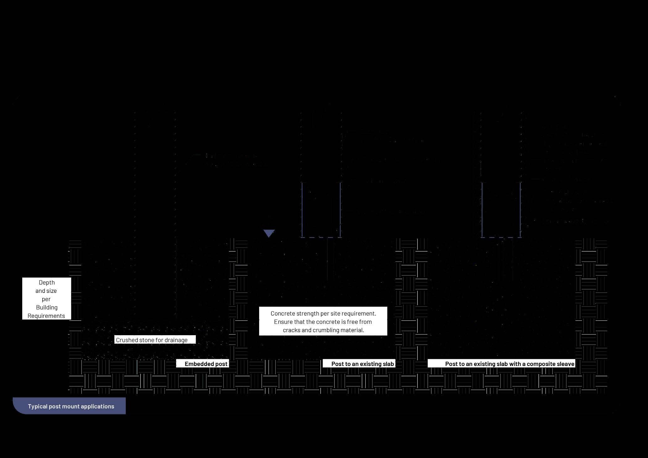
6.1.2 Embedded post
1. Dig post holes:
a. Consult local code requirements for exact post hole width and depth requirements. Consider frost lines, soil bearing capacity, post and fastener edge distance, and applied loads.
b. Locate and identify any buried utilities.
c. Dig the post holes using a Post Hole Digger.
d. Be sure to keep the Post Hole Digger straight and plumb when digging.
e. DO NOT POUR CONCRETE IN THIS STEP.
2. Set posts into holes:
a. Fill holes with 72 mm of crushed stone to allow for drainage.
b. Compact the crushed stone before setting posts.
c. Use tape measure to check depth. Confirm post depths are constant and comply with local building code. Adjust if needed.
d. Use the string as a guide when placing posts into each hole.
3. Pour concrete into holes:
a. BEFORE POURING CONCRETE, CONFIRM THE POSTS ARE SPACED CORRECTLY AND SET AT CORRECT DEPTH.
b. Fill posts holes with concrete to within 25 mm of the surface of soil.
c. Use a level to confirm that corner post is plumb and that the post is aligned with the guide strings.
d. Allow concrete to cure for a minimum of 24 hours before installing post brackets.
e. As the concrete cures, be sure to keep posts placed along guide strings & continuously check that they are plumb as well as in line with the next post.
6.1.3 Post on an existing slab
1. Ensure that the concrete is suitable to mount on:
a. The concrete should be free from cracks or crumbling material.
b. The slab should be level and flat. This may cause the post mount to distort and cause difficulty to fit the post and hold it plumb.
c. The concrete should have a minimum compressive strength of 20.7 MPa at 28 days, or as required by the design.
d. The depth of the slab should allow for sufficient withdrawal resistance as required by the design. At a minimum, this should be 110 mm.
e. The post mount should be have sufficient edge clearance as required by the design. At a minimum, this should be 40 mm.
2. Mark and drill the required holes:
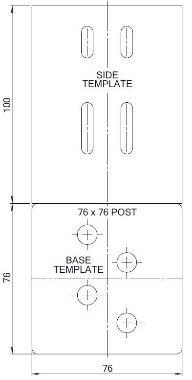
a. Use the template as a guide that is available from the appendix to mark the required locations of the holes.
b. Use some masking tape on the drill bit to ensure that the holes are drilled to the required depth. The depth is dependent on the design. At a minimum, this should be 80 mm.
c. Use a diameter 10 mm masonry drill the required M8 holes, while using the require PPE.
d. Clean the holes by blowing compressed air into each one.
3. Fix threaded rod into each hole:
a. Ensure that the correct grade material with the required coating is used. This is based on the design load and corrosion class. At a minimum, this should be galvanised grade 4.8 material.
b. Use a chemical anchor to secure the threaded rod. Follow the chemical anchor manufacturer’s instructions on hole preparation, use and drying time. It is recommended to use Hilti’s HIT-HY 100/110 adhesive anchor.
c. Ensure that a minimum of 20 mm of threaded rod protrudes from the slab.
d. Allow the chemical anchor to sufficiently dry.
e. Cut any excessive lengths of threaded off.
4. Secure the post mount to the slab:
a. Place the base plate over the holes – the base plate is optional.
b. Place the generic L bracket over the threaded rod.
c. Lightly secure with washers and nuts.
d. Check that the post fits over the L brackets and that is sits plumb and flush with the slab. If not, adjust the L brackets as necessary.
e. Remove the post and tighten the nuts holding the L brackets.
f. Place the post over the L brackets in its final position.
g. Pre-drill a 2-3 mm hole through the post and generic L bracket, using the template in the appendix as a guide.
h. Use four Z-point clip screws on either side of the post – use a low clutch setting to avoid damaging the Torx bit.
6.1.4 Fixing the composite sleeve over the post
1. The 102.5 x 102.5 mm post sleeve is designed to fit over a 76 x 76 mm square post.
2. The post sleeve is not a structural component and cannot be treated as such. It requires an internal suitably sized post to provide strength.
3. If the post is suitable sized and the screws were positioned according to the template then the sleeve will conveniently slide over the post.
4. The sleeve only needs to be secured if there is no fixing of a bearer or joist – see bearer and joist installation.
5. Install the appropriate end cap.
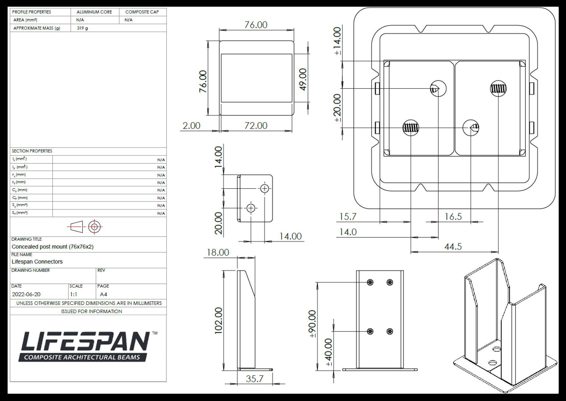
Concealed post mount assembly
Concealed Post Mount Assembly
L Bracket
L Bracket (x2)
Z-point clip screw (Sold separately)
Template
Base plate
M8 Threadrod or anchors (Sold separately)
Using a template drill 10 mm Ø hole for M8 Threadrod. Then blow out the hole and blow out prepare for chemical anchor.
20 mm Protruding M8 Rods*
Optional base plate
*(Minimum Galvanised grade 4.8)
Place Optional base plate before sliding L Brackets (x2) over the protruding thread rods
Before tightening bolts, Check that the post fits over and Adjust floor levels, adjust using spacers where needed
Slide steel tube over the post mount Using a template drill holes through the steel tube into the post mount
Fasten using Z-point clip screws Optional - A Composite sleeve can be mounted over the steel tube
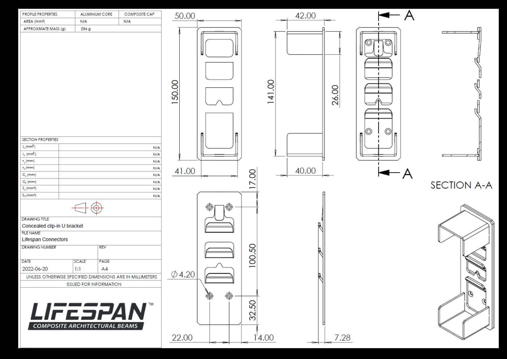
6.2 Bearer installation – concealed clip-in U bracket
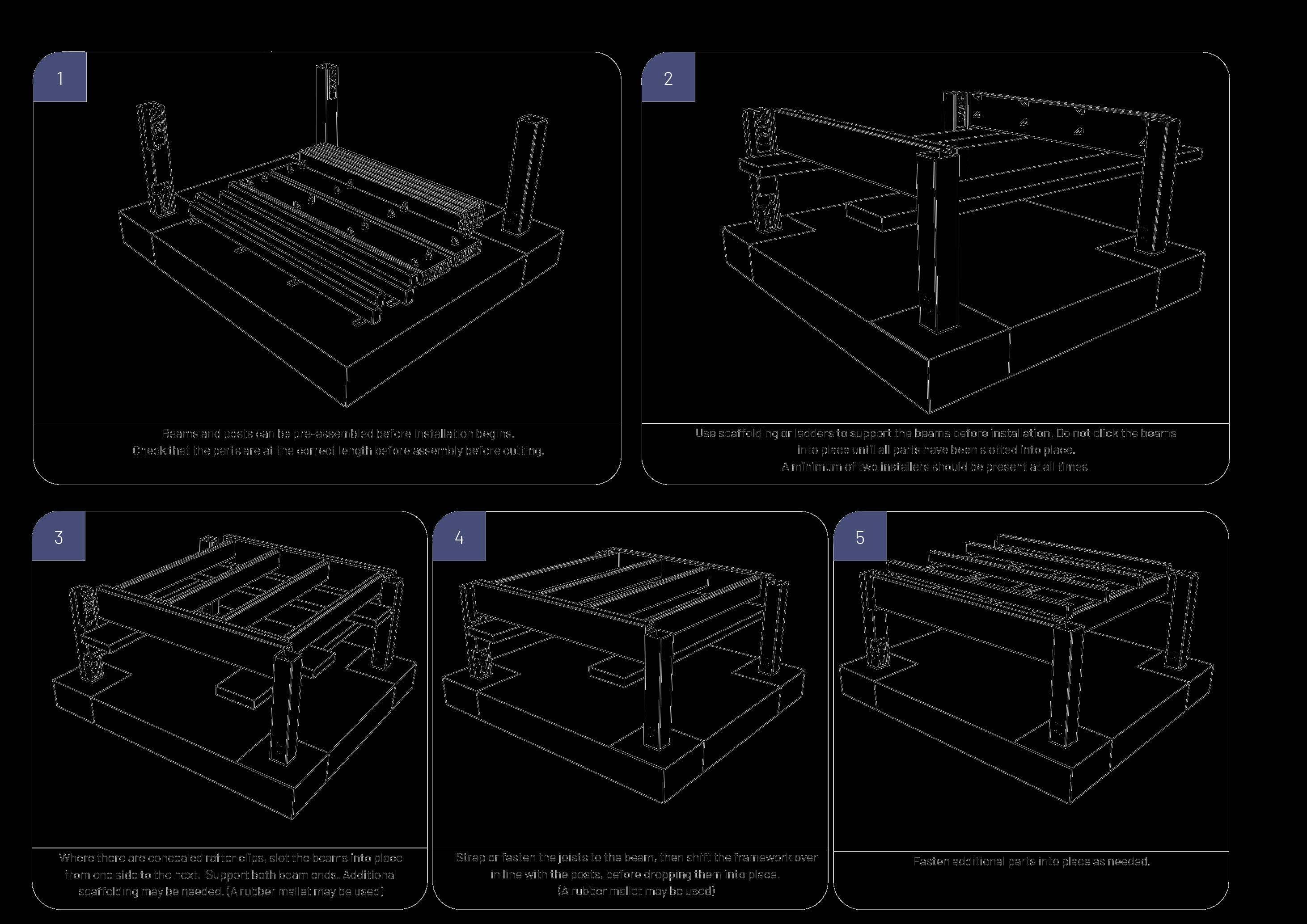
1. Place the mount plate onto the required mounting surface – ensure that the directional arrow points upwards.
2. Use the appropriate fastener for the mounting surface to fix the mount plate. If the mounting surface is a steel post or Lifespan beam, then the Z-point clip screw may be used.
3. Ensure that a low clutch setting is used to avoid stripping the fastener in the aluminium skeleton or damaging the Torx bit.
4. Insert all 4 screws into the mount plate.
5. Once the 150 x 50 mm Lifespan beam (i.e. the bearer) is cut to the correct length, push in the beam insert into the cavities.
6. Ensure that the directional arrows match that of the mount plate.
7. Lightly test fit the Lifespan beam and ensure that the connectors can be clipped into place, but do not fully clip them into place.
8. If there is some issue clipping in the connectors, softly bend open the clips of the mount plate to make clipping in easier.
9. With the Lifespan beam able to clip into place and back on the ground, finish installing the beam insert.
10. Install the screws as per the screw fastener section (Section 5.3.2).
11. Place a screw on either short side of the connector approximately 10 mm from the cut edge of the Lifespan beam and in centre of the beam.
12. With the beam insert installed on either side of the Lifespan beam, clip into the mount plate.
13. Lightly tap with a rubber hammer until clipped in.
14. Check that the beam is fully clipped in by lightly tapping upwards with a rubber hammer.
15. If the Lifespan beam unclips, bend the negative clip outwards slightly, and repeat the clipping in process.
Concealed post mount assembly
Mounting Plate Beam insert
Cut the 150 x 50 mm Lifespan beam (i.e. the bearer) to the correct length, before pushing the beam insert into place.
Using the appropriate template, or the base plate itself, Mark the hole locations.
Direction arrow
arrow
Lightly test fit the Lifespan beam into the post mount before fastening the beam beam inserts into place

Mark using a template and countersink holes into the composite in preperation for the Z-point clip screw
Pre-drill holes into the post using a 2 to 3.5 mm Drill bit. (Where a composite sleeve is used, Ensure that the bracket is fastened into the structural steel.)
Mounting plate
Place the mount plate onto the required mounting surface – ensure that the directional arrow points upwards.
Use the appropriate fastener for the mounting surface to fix the mount plate. If the mounting surface is a steel post or Lifespan beam, then the Z-point clip screw may be used.
1. Place a screw on either short side of the connector approximately 10 mm from the cut edge of the Lifespan beam and in centre of the beam.
2. With the beam insert installed on either side of the Lifespan beam, clip into the mount plate. Lightly tap with a rubber hammer until clipped in.
Check that the beam is fully clipped in by lightly tapping upwards with a rubber hammer.
6.3 Beam splicing
It is preferred that a post is used at any Lifespan beam splices. However, this is not always possible. Additional length is achieved by splicing two Lifespan beams together. Splice joints need to be carefully designed with consideration given to loading and corrosion. Consult a suitably trained professional when splicing beams together.
6.4 Joist installation
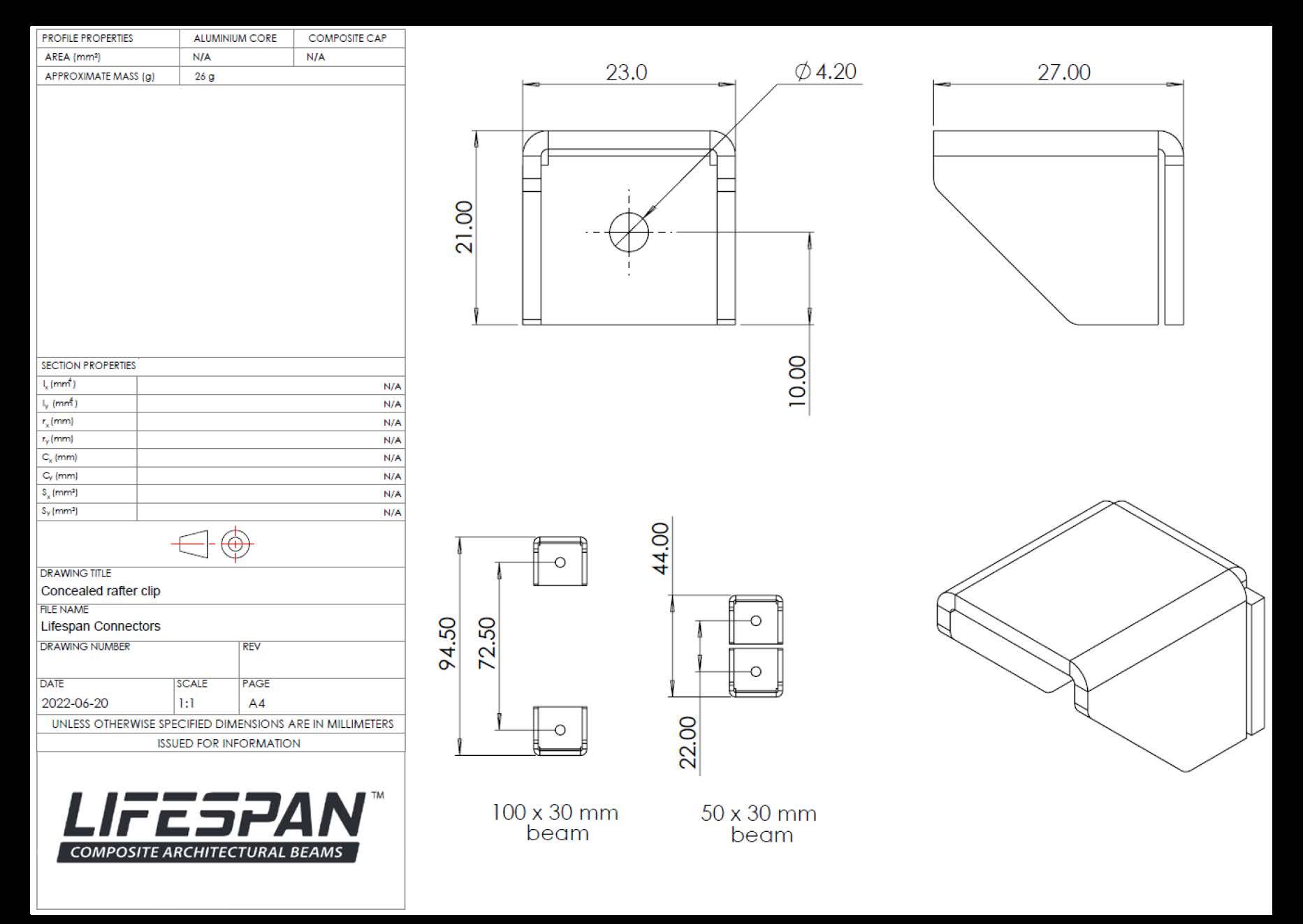
6.4.1 Installation using concealed rafter clips
1. Place the first concealed rafter clip onto the required mounting surface. It is helpful to use a small offcut of the Lifespan beam to be fixed to the surface as a guide.
2. The surface of the concealed rafter clip should be placed against the mounting surface.
3. Use the appropriate fastener for the mounting surface to fix the first concealed rafter clip. If the mounting surface is a steel post or Lifespan beam, then the Z-point clip screw may be used.
4. Ensure that a low clutch setting is used to avoid stripping the fastener in the aluminium skeleton or damaging the Torx bit.
5. Place the second concealed rafter clip in the correct location and fix to the mounting surface.
6. Install the screws as per the screw fastener section ( Section 5.3.2 ).
7. Place a screw on either short side of the connector approximately 10 mm from the cut edge of the Lifespan beam and in centre of the beam.
Place the first concealed rafter clip onto the required mounting surface. It is helpful to use a small offcut of the Lifespan beam to be fixed to the surface as a guide.
Use the appropriate fastener for the mounting surface to fix the first concealed rafter clip. If the mounting surface is a steel post or Lifespan beam, then the Z-point clip screw may be used.
Place the second concealed rafter clip in the correct location and fix it to the surface to which it will be mounted.
Prepare the beams, Countersinking holes approximately 10 mm from the edge
Slide the beams assembly together (A rubber mallet may be used where needed.)
Fasten the Joists (STLS01X and STLS09) to there matching concealed rafter clip. Locking the structure into place
STLS09 Beams require fasteners to be staggered.
6.4.2 Installation using connection plate
6.5.2 Installation using connection plate
1. Install the connection plate onto the bottom surface of the Lifespan beam using the two middle holes.
2. Use two Z-point clip screws to secure the connection plate.
1. Install the connection plate onto the bottom surface of the Lifespan beam using the two middle holes.
2. Use two Z-point clip screws to secure the connection
3. Ensure that a low clutch setting is used to avoid stripping the fastener in the aluminium skeleton or damaging the Torx bit.
and Z-point clip screws.
6. Ensure that a low clutch setting is used to avoid stripping the fastener in the aluminium skeleton or damaging the Torx bit.
4. Place the Lifespan beam with the connection plate in its required location.
5. Fix the connection plate in its required position by using the 4 remaining holes and Z-point clip screws.
6. Ensure that a low clutch setting is used to avoid stripping the fastener in the aluminium skeleton or damaging the Torx bit.
two Z-point clip screws to secure the connection plate.) Place the Lifespan beam with the connection plate in its required location. Fix the connection plate in its required position by using the 4 remaining holes and Z-point clip screws.
IMPORTANT - Ensure that a low clutch setting is used to avoid stripping the fastener in the aluminium
6.5 Batten installation
6.5.1 Visible screw fastener
1. Use a Z-point clip screw to fix the batten to a Lifespan beam. The Z-point clip screw is only suitable for low withdrawal loads, as large loads will cause the screw head to pull through the batten. If additional strength is needed, a screw with a large head may be sourced.
2. Do not predrill Lifespan beam.
3. Fasten the screw - the batten material’s softness will allow the screw to pull into the batten slightly.
4. Ensure that a low clutch setting is used to avoid stripping the fastener in the aluminium skeleton or pushing the screw to deeply into the batten.
5. Alternatively, a depth-setting bit may be used.
6.6.1 Visible screw fastener
1. Use a Z-point clip screw to fix the batten to a Lifespan beam. The Z-point through the batten. If additional strength is needed, a screw with a
2. Do not predrill Lifespan beam.
3. Fasten the screw - the batten materials softness will allow the screw
4. Ensure that a low clutch setting is used to avoid stripping the fastener
5. Alternatively, a depth-setting bit may be used.
6.5.2 Hidden screw (plug) method:
1. Predrill the composite batten to the appropriate size. Use 2 – 3 mm if a Z-point clip screw is being used.
Cut a plug of the same diameter as the counter bore with a plug cutter. Cut the plug to the depth of the screw plus an additional 1 mm.
2. Counter bore the batten to a diameter larger enough to fit the fastener head and to match the plug cutters diameter. 3. Do not predrill the Lifespan beam.
Measure the depth of the top of the screw head to the top of the batten.
4. Use a Z-point clip screw to fix the batten to a Lifespan beam. The Z-point clip screw is only suitable for low withdrawal loads, as large loads will cause the screw head to pull through the batten. If additional strength is needed, a screw with a large head may be sourced.
Predrill the composite batten to the appropriate size. Use 2 – 3 mm if a Z-point clip screw is being used.
5. Fasten the screw - the batten material’s softness will allow the screw to pull into the batten slightly.
Predrill the composite batten to the appropriate size. Use 2 – 3 mm if a Z-point clip screw is being used.
6. Ensure that a low clutch setting is used to avoid stripping the fastener in the aluminium skeleton or pushing the screw to deeply into the batten.
7. Cut a plug of the same diameter as the counter bore with a plug cutter.
8. Measure the depth of the top of the screw head to the top of the batten.
9. Cut the plug to this length plus an additional 1 mm.
Do not predrill the Lifespan beam.
10. Apply a suitable glue and light tap the plug in with a rubber mallet – the plug should be slightly proud of the batten.
2. Do not predrill Lifespan beam.
5. Alternatively, a depth-setting bit may be used.
deeply into the batten.
11. Wipe away excess glue.
12. Once the glue has fully cured, lightly sand the plug until it is flush with the batten.
Cut a plug of the same diameter as the counter bore with a plug cutter.
Cut the plug to the depth of the screw plus an additional 1 mm.
Measure the depth of the top of the screw head to the top of the batten.
Predrill the composite batten to the appropriate size.
Use 2 – 3 mm if a Z-point clip screw is being used.
Predrill the composite batten to the appropriate size.
Use 2 – 3 mm if a Z-point clip screw is being used.
Do not predrill the Lifespan beam.
6.6 End cap installation
1. Apply a suitable glue and light tap the plug in with a rubber mallet – the plug should be slightly proud of the batten.
2. Wipe away excess glue.
3. Once the glue has fully cured, lightly sand the plug until it is flush with the batten.
Colour-matched end caps are available for each Lifespan beam and are designed to fit into each beam. The preferred installation procedure is detailed below:
1. Clean the end cap and beam from any oils, grease, or dirt by using a light solvent,
2. Use a transparent quick-drying glue that is suitable for HDPE and aluminium, and the environment,
3. Apply glue onto the surfaces of the end cap,
4. Insert the cap into the end of the beam – quickly wipe away any excess glue,
5. A light tap with a rubber mallet may be required to fully insert the end cap,
6. Once the glue has fully cured, lightly sand the edges of the end cap to fully fit the beam profile.
1 2
1. Clean the end cap of any oils, grease, or dirt by using a light solvent.
2. Use a transparent quick-drying glue that is suitable for HDPE and aluminium, and the environment.
3. Apply glue onto the surfaces of the end cap.
The glue should be:
• Transparent
• Moisture resistant
• Suitable for the temperature range of the environment
• Suitable for high-density polyethylene (HDPE) and aluminium.
Some examples of a suitable glues include:
• Sikaflex crystal clear
• Scotch weld DP-8010
General notes:
1. Clean the end cap of any oils, grease, or dirt by using a light solvent.
2. Insert the cap into the end of the beam – quickly wipe away any excess glue.
3. A light tap with a rubber mallet may be required to fully insert the end cap.
4. Once the glue has fully cured, lightly sand the edges of the end cap to fully fit the beam profile.
• Some glues may stain the Eva-tech composite end cap or composite cap of Lifespan beam. It is advised to test the glue on a small scrap piece to determine if there is staining.
• The end caps have weep holes to allow for condensation and must not be blocked.
7. Important considerations
7.1 Lifespan beam loads and spans
7.1.1 Load considerations
The information provided below is specifically intended to supply the user with context of the complexity behind the design of an application. This information is not intended as a guide to design, a suitably competent professional should be consulted for any design requirements. When assessing the potential loads of an application, several load types, as well as the combinations thereof, need to be considered. Load types typically include:
• Dead loads
• Live loads
• Wind loads
• Snow loads
• Rain loads
• Seismic loads, etc.
These loads can occur as both concentrated and distributed loads, and both scenarios are typically assessed. The values of which, and how they are combined, depend on design standards of the region and the application. The design of the system should satisfy the worst-case load scenario of any stage of the structure’s design life, this can include the construction phase.
A simplified example of a load assessment is provided below. This is purely indicative, utilising fictional values for information purposes.
Dead load ( DL ): Consists of the structure’s mass only, no additional components present. Dependent on the design and layout.
DL = 0.14 kPa
Live load ( LL ): Assume no covering, as a result, only the individual members are loaded. The framework is accessible during construction, otherwise it is inaccessible.
LL = 0.25 kPa
Wind load ( WL ): Fundamental wind speed is 25 m/s, with terrain roughness is flat horizontal with negligible vegetation and without any obstacles, reference height is 3 m and the structure is built at sea level.
WL = 0.88 kPa.
All other loads are assumed to be negligible.
The worst-case load combinations for this example are assumed to be one of the following based on the above applicable loads:
1.2 DL + 1.6 LL = 0.57 kPa
0.9 DL + 1.0 WL = 1.01 kPa
The line loads carried by each Lifespan beam is dependent on the design and where each member is located within the layout of the structure.
For this example, a simple 3 x 3 m pergola with a post at each corner is assumed. Bearers are employed to connect the four posts. Joists are then installed in-line between the bearers, with battens fixed perpendicularly above the joists to provide cover. Simple schematics are provided below.
Based off of the above layout, the members will experience the following line loads:
Bearer = 0.51 kN/m
Joist = 0.46 kN/m
Batten = 0.25 kN/m
Once the line loads have been determined, the Lifespan profiles and their respective spans can be refined. This will alter the original load applied to the structure and, as a result, the line loads are to be recalculated to confirm if the selected profiles remain suitable for the application. The following section provides span tables summarising suitable spans for each profile based on the applied loads and orientation of the beams. The tables are used to determine an appropriate profile and span for the calculated loads.
7.1.2 Lifespan beam dead loads
The span of the Lifespan beams are partially governed by its own weight. The table below shows the linear weight and mass of each Lifespan beam. This may be added to additional line loads applied to the beam. This is expanded and the mass of typical beam length are shown in adjacent columns.
7.1.3 Span tables
Suitable spans are determined by estimating the moment resistance provided by the aluminium core of the Lifespan beams. Flexural test results indicate that this is a conservative approach, however, it simplifies the method to components that are more familiar to professionals that would be utilising these products.
The spans provided are calculated based on the following assumptions and methods:
Material: Aluminium 6063 T5
Yield strength ( σᵧ ): 145 MPa
Material factor ( ƒ ): 0.9
Sectional properties of the Lifespan beam profiles are taken from the Lifespan Technical Datasheet.
No additional safety factors have been added.
For cantilever beam: M = ƒσ = L =
For simply supported beam:
M = ƒσ = L =
Tributary area
Rafter spacing
Converting from distributed pressure into a line load can be done through the following table. The table applies the pressure to the tributary area applied to the beam. The tributary area is typical equal to the rafter spacing, however this is dependent on the specific design.
The following tables provide spans as they relate to specific loads and the orientation of the profile with respect to the load direction. These tables show the limiting span between serviceability and strength considerations, where serviceability is governed by L/180.
150 x 50 mm Lifespan beam span table
100 x 30 mm Lifespan beam span table
Simply-supported applications
Cantilever applications
50 x 30 mm Lifespan beam span table
Simply-supported applications
Cantilever applications
Apex batten span table
applications
Continuing the example above of the 3 x 3 m pergola. The suitability of the bearer is this application may be assessed.
1. Find the appropriate span table for the beam being used. In this case, it is the 150 x 50 mm Lifespan beam.
2. Go down the table to the appropriate line load. The line load on this beam was assessed to 0.51 kN/m.
3. Go across the table to the suitable application, either simply-suitable or cantilever. In the design the beam is used in a simply-supported application.
4. Decide on the orientation that the beam is mounted in. In this design, the beam is mounted vertically and the load is applied on the short side.
5. Go down the table and find the maximum allowable span of 6.74 m.
6. The design of this pergola requires a bearer span of 2.8 m. This is well below the maximum allowable span of 6.74 m – hence this Lifespan beam is safe to use in this application.
150 x 50
Repeating this process for the joist that has a line load of 0.46 kN/m with the 100 x 30 mm Lifespan beam. The joist span is 1.4 m, which is less than the maximum allowable span of 3.35 m.
For the batten that has a line load of 0.25 kN/m with the 40 x 30 mm Apex batten. The batten span is 0.74 m, which is less than the maximum allowable span of 1.94 m.
7.2 Lifespan connector loads
The connections of a structure must be specified and installed so to safely carry and transfer loads experienced by the structure. Eva-Last’s range of Lifespan connectors have been designed to meet typical pergola loads. For a safe application, ensure that the loads experienced by the connections are well within the limits summarised below. An estimated ultimate load and a maximum recommended design load assuming a safety factor of 2.5 is supplied for convenience. Inspections of installations should be carried out by a suitably competent professional to ensure adequate fixing and, therefore, transfer of loads, etc. Regular inspection and maintenance of the system should be employed to ensure the longevity of the system. The information provided below is for convenience and all connections should be assessed and designed by a suitably competent professional to ensure all standard and application requirements are appropriately satisfied.
7.2.1 Concealed post mount
This connector has poor moment resistance, as a result, the posts should be adequately braced within a rigid frame.
7.2.2 Concealed clip-in U bracket
This connector has no moment resistance and, as a result, should not be used in cantilever applications or scenarios susceptible to these types of loads
7.2.3 Concealed rafter clip
The moment resistance is heavily influenced by the substrate the connector is fixed to and the resultant fixings used. Values provided here are of a connection into another Lifespan beam using the Z-point clip screws. This connector has poor moment resistance and, as a result, should not be utilised in scenarios susceptible to these types of loads.
Once again continuing from the 3 x 3 m pergola example from above.
For the bearer, the following steps are followed:
1. This design asks for a bearer with the following:
a. Span: 2.9 m
b. Line load: 0.51 kN/m
c. Application: Simply-supported beam, i.e. a connector on either side of the beam
d. Connector: Concealed clip-in U bracket
2. The total load on the beam is the line load multiplied by the span. In this example, the total beam load is 1.48 kN (= 2.9 m x 0.51 kN/m).
3. In this design, under a simply-supported application, each connector carries half the load of the beam, i.e. 0.74 kN per a connector.
4. Using the applicable table for this connector, the downward design load is 1.90 kN. This is greater than the applied load of 0.74 kN, hence the connector is safe to use in this application.
This process is repeated for the concealed rafter clip used on the joist. The total load is 0.64 kN (= 1.4 m x 0.46 kN/m). Again, under a simply-supported application, each connector carries half the load, i.e. 0.32 kN. This is lower than the downward design load of 4.4 kN, hence this connector is safe to use in this application.
7.3 Screw data applicable to Lifespan beams
This section captures information about typical fasteners that may be used with the Lifespan beams and connectors. For a safe application, ensure that the loads experienced by the fasteners are well within the limits summarised below. Inspections of installations should be carried out by a suitably competent professional to ensure adequate fixing and, therefore, transfer of loads, etc. Regular inspection and maintenance of the system should be employed to ensure the longevity of the system. The information provided below is for convenience and all fasteners should be assessed and designed by a suitably competent professional to ensure all standard and application requirements are appropriately satisfied.
7.3.1 Z-point MDS screw
The Z-point MDS screw is recommended to use when attaching the Lifespan connectors to Lifespan beams and vice versa. The screw has the following features.
Feature
Screw dimensions
Screw material
Screw coating
Head type
Drill point type
Effective thread length
Pre-drilling hole size (if applicable)
Value
M4.2 x 32 mm
Carbon Steel – C1022
Magni 599 dark brown epoxy (~ 20 μm thick)
Pan head
Pre-drilling point
30 to 31 mm
3.3 mm
The Z-point MDS screw withdrawal resistance was tested by CCT. The ultimate torque was estimated using internal test results.
out resistance
Density of pine 670 kg/m³
Tests conducted by CCT
Density of Apex 750 kg/m³
Tests conducted on profile STPVB104 by CCT
Density of Eva-tech 1 300 kg/m³
Tests conducted on profile ST08X profile by CCT
Tests conducted on STLS09 profile by CCT
7.3.2 Quick reference guide for typical fasteners
The following table provides a quick reference list of typical fasteners that may be used for various substrates. This information has been collected from several manufacturers for convenience and is presented herein to provide indicative performance. Please refer to applicable manufacturers for further information and/or confirmation of the suitability of the application. Appropriate fasteners must be utilised. Particular attention should be paid to substructure/substrate and environmental conditions (particularly with respect to corrosion) of the site. All applications should adhere to applicable standards. All timber and metal profiles should be treated and/or coated appropriately. Regular proactive maintenance is advised where possible.
*Refer to actual suppliers TDS for specific information, including coating and material thicknesses.
Devoid of cracks and similar. Typical embedment depth of
Confirm adequate strength. Refer to Hilti TDS.
Devoid of cracks and similar. Typical embedment depth of
Confirm adequate strength. Refer to Hilti TDS.
7.4 Thermal expansion and contraction
It may be necessary to compensate for changes in the Lifespan beam length due to the expansion or contraction induced by a change in temperature. This change is influenced by the temperature range of the site, type of material, length of the profile, layout employed, and type of connections utilised. A simplified method to estimate the expected expansion or contraction is captured below. If additional information is required, consult a suitably qualified professional or contact Eva-Last.
To estimate the change in length ( ΔL ) per Lifespan beam, multiply the length of the Lifespan beam ( L) by the thermal coefficient of the material ( ɑ ) and by the difference in temperature between the installation temperature and the anticipated maximum possible temperature of the Lifespan beam:
ΔL = L x ɑ x (Tmax – Tinstall)
Where:
• ΔL = increase in Lifespan beam length due to temperature change, in mm.
• L = initial length of Lifespan beam at installation temperature, in mm.
• ɑ = linear thermal expansion coefficient of the material. For Lifespan beams, the aluminium core will dictate, a typical coefficient of which is 0.023.
• T max = the maximum temperature that the Lifespan beam is anticipated to reach, in degrees Celsius.
• Tinstall = the Lifespan beam temperature at the time of installation, in degrees Celsius.
Use the same method to estimate the contraction of the Lifespan beam, where the maximum temperature is replaced with the minimum possible temperature. Combining these two changes in length provide an estimate of the total possible change in length for the application.
Ensure that the connections utilised are able to cater for this range of expansion and contraction. Grooved holes with appropriate fasteners can provide additional capacity at these points if required. If the anticipated movement is still too large, shorter spans should be implemented.
7.5 Corrosion
The required corrosion resistance of a structure depends on its environment and the requisite design life. Materials should be selected such that the structural integrity and aesthetic appearance is maintained throughout the structures’ intended lifespan. Typical information regarding corrosion environments and rates is provided in Appendix D for convenience.
It is often necessary to also consider galvanic corrosion between dissimilar metals when multiple materials are utilised in an installation. Galvanic corrosion occurs when different metals are in contact in the presence of an electrolyte . Several approaches can be utilised to minimise the impact of galvanic corrosion such as insulation of the metals from one another, utilisation of materials of a similar nobility, ensuring corrosion of the less noble metal will not negatively impact the connections, etc. Additional information regarding galvanic corrosion is provided in Appendix D for convenience.
Disclaimer and copyright
Document disclaimer
The provided information is offered in good faith as accurate but without guarantee. Eva-Last makes no warranties or representations of any kind (express or implied) about the accuracy, adequacy, currency, or completeness of the information, or that it is necessarily suitable for the intended use.
Compliance with this document does not guarantee immunity from breach of any statutory requirements, building codes or relevant standards. The final responsibility for the correct design and specification rests with the designer and, for its satisfactory execution, with the contractor. Appropriate warnings and safe handling procedures should be provided to handlers and users.
While most data have been compiled from research, case histories, experience and testing, small changes in the environment can produce marked differences in performance. The decision to use a material, and in what manner, is made at your own risk. The use of a material and method may therefore need to be modified to its intended end use and environment.
Eva-Last, its directors, officers or employees shall not be responsible for any direct, indirect, or special loss or damage arising from, or as a consequence of, use of, or reliance upon, any information contained in this document or other documents referenced herein. Eva-Last expressly disclaims any liability which is based on or arises out of the information or any errors, omissions or misstatements herein.
Drawing disclaimer
All dimensions and specifications are offered in good faith as accurate but without guarantee. The information captured herein may not contain complete details. Eva-Last makes no warranties or representations of any kind (express or implied) about the accuracy, adequacy, currency, or completeness of the information, or that it is necessarily suitable for the intended use.
Compliance with this document does not guarantee immunity from breach of any statutory requirements, building codes or relevant standards. The final responsibility for the correct design and specification rests with the designer and, for its satisfactory execution, with the contractor.
Utilisation disclaimer
Legislation may differ between jurisdictions. Before installing any Eva-Last product, ensure that the application is rational and complies with the local regulations and building codes. Wherever necessary, consult a suitably qualified professional. Be sure to comply with material manufacturer specifications. Where manufacturers and building codes differ, revert to the building code requirements. Check that your choice of product is suitable for its intended application. For further product specification and information visit www.eva-last.com
Copyright
If reprinted or reproduced or utilised in any form Eva-Last should be acknowledged as the source of the information.
Eva-Last periodically updates the information contained in this document as well as that of the Eva Last documents that have been referenced herein. Before using this document, please refer to the Eva-Last website (www.eva-last.com) for the most up-to-date documents.
Contact information
Eva-Last
Email: info@eva-last.com
Website: www.eva-last.com
Appendix A
Lifespan beam drawings
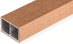
Lifespan profiles
See TDS for additional information where required
The following table summarizes all available profiles; this may differ by region.
The mass provided are estimates and based on the density and area of the profile.
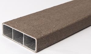
Lifespan - Architectural beams - For TDS - STLS01x
Lifespan - Architectural beams - For TDS
profile - STLS01x


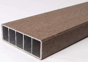
- Architectural beams - For TDS - STLS02
- Architectural beams - For TDS


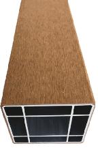
Lifespan - Architectural beams - For TDS - STLS06
Lifespan - Architectural beams - For TDS
profile - STLS06


- Architectural beams - For TDS - STLS07
- Architectural beams - For TDS
profile - STLS07


Lifespan - Architectural beams - For TDS - STLS08
Lifespan - Architectural beams - For TDS


APPROXIMATE
4 I (mm ) (mm4 )
r (mm)
r (mm)
C (mm)
C (mm)
S (mm³)
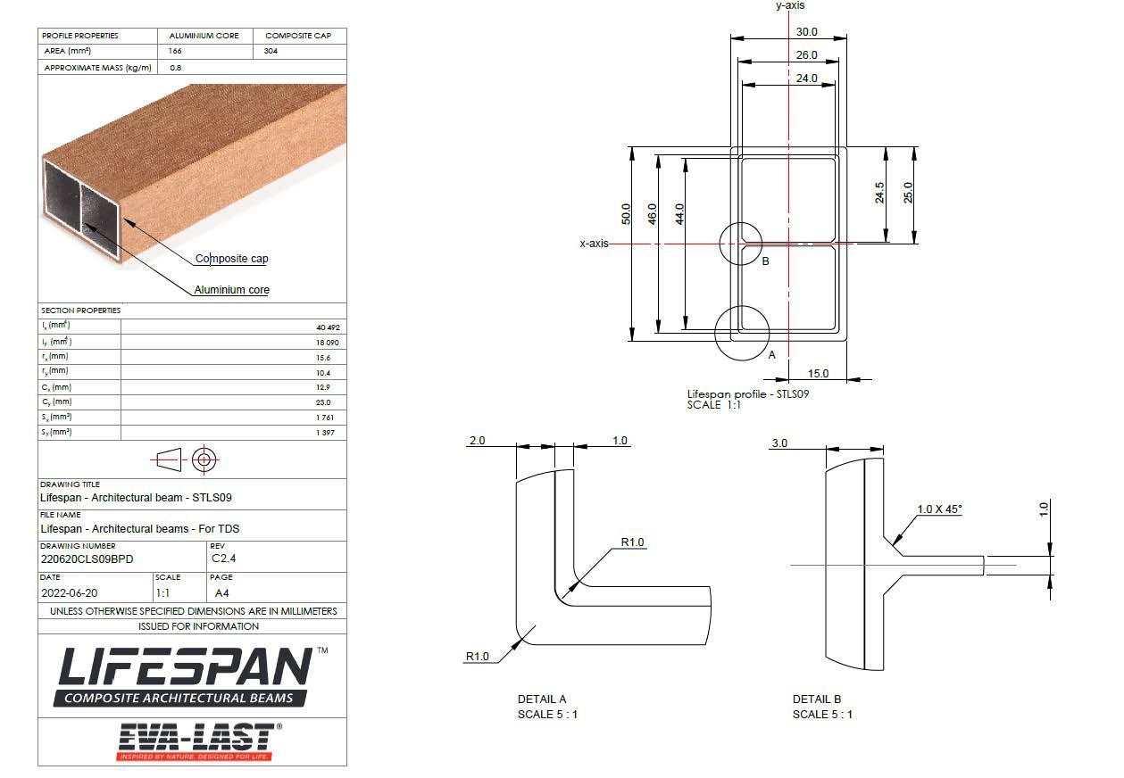
Lifespan profile - STLS09
Lifespan - Architectural beam - STLS09
Lifespan - Architectural beams - For TDS
220620CLS09BPD C2.4


Appendix B
Lifespan connector drawings
Appendix C
Concealed post base
Concealed post base
This template can be printed and used as a guide to correctly position the holes and screws.
To print only this page:
• Go to Print Settings
• Ensure that there are no scaling effects
• Select Current Page, alternatively if this option is not available choose Custom Range and enter in “36”
How to use this template:
• Print this page
• Place the template in the required position for the connector
• Use a sharp tool such as an awl to mark the substrate beneath the template
• Remove the template
• Drill the require holes or insert the required screws in the marked positions
Concealed clip-in U bracket
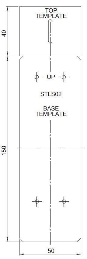
This template can be printed and used as a guide to correctly position the holes and screws.
To print only this page:
• Go to Print Settings
• Ensure that there are no scaling effects
• Select Current Page, alternatively if this option is not available choose Custom Range and enter in “37”
How to use this template:
• Print this page
• Place the template in the required position for the connector
• Use a sharp tool such as an awl to mark the substrate beneath the template
• Remove the template
• Drill the require holes or insert the required screws in the marked positions
Concealed rafter clip
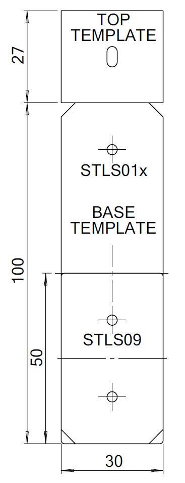
This template can be printed and used as a guide to correctly position the holes and screws.
To print only this page:
• Go to Print Settings
• Ensure that there are no scaling effects
• Select Current Page, alternatively if this option is not available choose Custom Range and enter in “38”
How to use this template:
• Print this page
• Place the template in the required position for the connector
• Use a sharp tool such as an awl to mark the substrate beneath the template
• Remove the template
• Drill the require holes or insert the required screws in the marked positions
Appendix D
Corrosion information
Material
corrosion rates
The following table provides typical corrosion rates (μm / annum) for common materials seen in composite building systems. Not all materials are published in relation to ISO 9223 corrosion rates but are indicated by source material as suitable for certain environments. It has been assumed that references to a marine environment would be equivalent to a C5 environment.
Corrosion rates (μm/annum) of constituents in different corrosion zones
Material Category
Corrosion Classification macro versus micro-environments.
The following table provides a brief overview of the generalised environmental classifications of macro environments based on ISO 9223 standards. Without considering microenvironments on sites, that may affect the corrosion rate, such as temperature, wind direction, exposure, rain wash, pollutants, humidity, material etc.
Macro environments as classified by ISO 9223
Galvanic corrosion
Below is a summary providing an indication of metal combinations that are susceptible to galvanic corrosion when using typical products in conjunction with the Lifespan beams. Additional analysis of the environment or installation is advised when these conditions are likely to occur. Alternative materials or appropriate controls should be designed and implemented where necessary. An appropriately qualified professional should be consulted where necessary.
Red – Potential for galvanic corrosion
Orange – Possible to avoid galvanic corrosion through appropriate design.
Green – Same metal
Blue – Combination of materials has a low potential for galvanic corrosion.
Interaction between dissimilar metals
Anodic Metals (Red=Corrodes) Cathodic metals Zinc and alloys Aluminium and alloys Steel (carbon)
Zinc and alloys
Cast iron Stainless steel Notes
Galvanised steel coatings and a common screw coating
Aluminium and alloys Lifespan beam
Steel (carbon)
Cast iron
Stainless steel
Common fastener and structural material
Common material in moulded steel brackets
Common fastener material
