Since establishment in 1987 in Five Dock, NSW, Independent Timber Importers has been on a mission to redefine the timber industry wholesale/distribution landscape. ITI has worked closely with industry suppliers, customers and associations to promote the strength, beauty and environmental benefits of using timber. At the same time ITI redefined the role of the wholesaler with its distribution and service models. With its large investments in distribution centres, product development, people and service standards; in early 2002 ITI dropped the name Independent Timber Importers and replaced this with ITI and introduced the new logo with the “Innovative Timber Ideas” phrase which more accurately describes the attitude of the company.
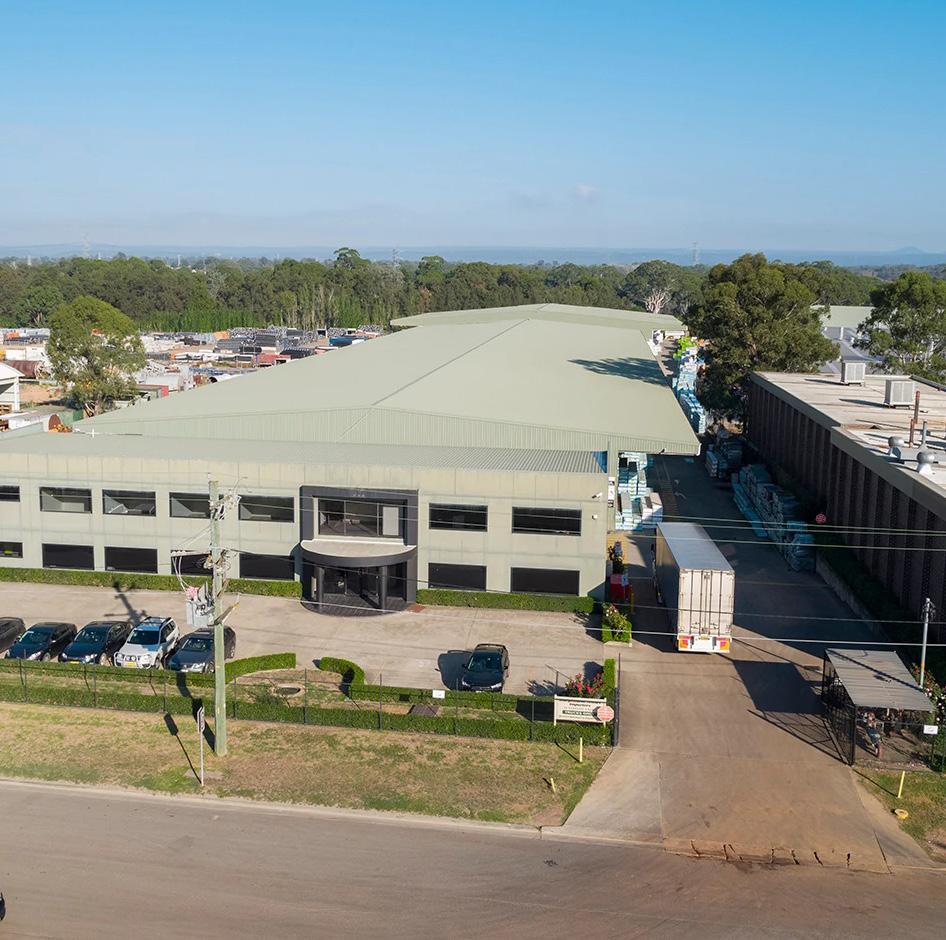
Today ITI consists of 9 distribution sites across Australia with over 140,000m2 of undercover storage, a state of the art re-manufacturing, treating and priming plant in Chile, an office in Indonesia, 3 distribution locations in New Zealand and growing sales in the USA.
True to its name, the success of ITI lies in its commitment to innovation in both service and product development. This commitment has led to premier brands such as Design Pine, EziTrim Plus and Spec Frame along with the distribution of market leading products such as Pacific Woodtech, Metsa Wood, Weathertex and Modwood. ITI has also led the way with service standards winning countless industry awards for its service.
ITI Engineered Wood Products
ITI sources Engineered Wood Products from leading manufacturers to ensure the needs of building designers through to the end-users are met with the best available products.
ITI’s Engineered Wood Products offering is comprised of three major products, each intended to complement the next: Laminated Veneer Lumber (LVL), I-Joists, and Glue-Laminated Timber Beams (GLT). These products, along with innovative construction details and dedicated support staff, provide a platform that sets ITI Engineered Wood Products apart from the rest.
Single Member Design Software
Available from ITI Australia is ITI Design Spec. A single member design software developed to assist industry professionals with the specification of ITI’s vast range of structural timber products. Free licences are available to suit builders, timber merchants, frame & truss professionals and engineers.
Email ewp@iti.net.au for details on how to accesss.
Hyne Design is a free to register structural design platform for timber designers of all experience levels a tool to specify ITI and Hyne Timber’s broad range of structural timber products. To request access please email ewpvic@iti.net.au
Note: Users are required to meet the requirements of the ABCB Structural Software Protocol to obtain access.
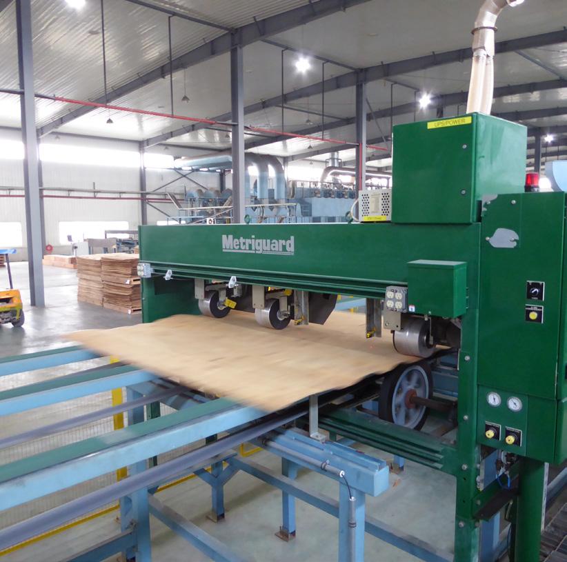
ITI Spec Joists are engineered wood joists manufactured by Metsä Wood, a leading supplier of wood products throughout Europe and the world. These joists are typically used in construction to provide structural support for floors and roofs. ITI Spec Joists are known for their strength, stability, and sustainability, making them a popular choice for builders and construction projects. Metsa ITI Spec Joist (SJI) I-Joists are constructed with lightweight, 36mm or 39mm thick Metsa Kerto LVL for the top and bottom flanges, connected by a high-performance Oriented Standard Board (OSB) web and offer excellent load-carrying capacity while being lightweight and environmentally friendly. ITI Spec Joists come in various sizes and configurations to suit different building needs and are designed to meet high-quality construction standards.
Available in lengths up to 12.0 metres long
Widely available with short order lead times
Fully compliant of internationally recognized standards
Does not contain any Russian or Belarusian wood fibre
Treatment
Distributed by ITI Australia, ITI Spec Joists (SJI) come standard with H2-S treatment for protection against termites and inspects below the Tropic of Capricorn.
Characteristic values for ITI Spec Joist (SJI) I-Joists have been evaluated by an appropriately qualified engineer and converted for use in Australia using internationally recognized evaluation reports, physical testing data and relevant Australian Standards. Referenced documents include:
Evaluations, Reports & Statements:
• Eurofins Report ETA 02/0026 EAD130367-00-0304
Product Manufacturing Standards & Guides:
• EN 12369-1: Characteristic Values - Structural Panel Products
• EU 300: OSB Definitions, Classification and Specifications
• EN 301: Adhesives, phenolic and amino-plastic, for load-bearing timber structures - Classification and performance requirements
Additional Standards Referenced Include:
• ISO TC165/CD 22389 Timber Structures - Bending Applications of I-Beams Part 1: Structural testing, Evaluation and Characterization
• AS4063.1 : 2010 Characterization of structural timber Part 1: Test methods
• AS4063.2 : 2010 Characterization of structural timber Part 2: Determination of characteristic values
• AS1720.1: 2010 Timber Structures Part 1: Design methods
• AS1170.1: 2002 Structural design actions Part 1: Permanent, imposed and other actions
Notes:
1. ITI Spec Joist (SJI) I-Joists shall be designed for dry-use conditions only. Dry-use applies to products installed in dry, covered and well ventilated interior, conditions in which the equivalent moisture content in timber will not exceed 16%.
2. All values may be adjusted for load duration (k1) as permitted in AS1720.1 excluding EI, k and vertical load capacity.
3. Deflection calculations shall include both bending and shear deformations.
Deflection for a simple span, uniform load: = ∆ = 5wL4 + wL2 384EI k Where:
∆ = Deflection (mm)
EI = bending stiffness (from table)
k = Coefficient of Shear Deflection (from Table)
w = uniform load (kN/m)
L = design span (mm)
FLOORS JOISTS & BLOCKING REQUIREMENTS
Floor joists are structural members arranged in a parallel series, designed to bear the weight of floor loads. The spacing of floor joists must align with the specifications of the supported flooring or floor sheet
Blocking Size Requirements
I-Joist or Solid Timber
Blocking Type
1 Intermittent blocking over external support at start / end of joist run
2 Intermittent blocking over internal support at start / end of joist run
3 Intermittent blocking over external support at 1800mm centres
4 Continuous Blocking to cantilevered joists
5 Rimboard / Fascia Beam to ends of cantilevered joist
Common Studs
Full Height Blocking min. 35mm Thick
Blocking to Concentrated Loads
Concentrated Load
Bottom Plate Floor Joists
Blocking is essential to offer resistance against lateral loads applied to the floor diaphragm and to transfer concentrated loads down into the supporting structure. Unlike standard blocking, Concentrated Load Blocking must be full height and a minimum of 35mm thick.
Rimboard
Rimboard can serve as a form of blocking and bracing for floor and roof framing systems. Additionally, rimboard has the capability to transfer certain horizontal and vertical loads through the floor diaphragm, as indicated in Details A1 and C1.
Web Infill is employed to reinforce the I-Joist when augmentation is necessary, such as for shower set downs, or to rectify incorrectly cut members, like misplaced plumbing penetrations
Fix 1x 75x3.05 nail to each top and bottom flange
Connection of flooring sheets to rimboard per flooring manufacturers requirements
Rimboard to top plate via 75x3.05 nails skewed at 150mm centres
Point Load Capacity of I-Joist Blocking or Perimeter Joists
ITI Spec Joists I-Joist may be used as a perimeter joist under the provision that any imposed loads greater than those nominated in the adjacent table have additional transfer / squeeze blocks installed. Refer to details A10 and B3.
WEB STIFFENING REQUIREMENTS
Web stiffeners are required to be fitted to both sides of an I-Joist when:
1. Additional non uniform loads are applied to the top of I-Joists (Subject to design. Refer to details A10 & B7);
2. The bottom flange of the I-Joists are notched to accommodate steel or LVSIA connections (Refer to detail E9);
3. Additional support bearing strength is required (Refer to detail B1 & H1); or
4. Joist hangers do not restrain the top flange by more than 20mm (Refer to detail E3) Web Stiffener Requirements for use with Joist Hangers PART 1
Web stiffeners required under load bearing walls
30mm minimum end support length required
Web stiffeners are required where joists hangers do not restrain the top flanges by a minimum of 20mm
63mm minimum intermediate support length required
Web Stiffener Requirements for use with Joist Connectors
Web Stiffener Requirements for use with Joist Hangers PART 2
Notes:
1. Where Web Stiffeners are required for use with shallow joist hangers the thickness is required to be that of the distance between the web and the outside of the flange
2. Web stiffeners shall be cut to fit between the flanges of ITI Spec Joist I-Joists, leaving a minimum 2mm and a maximum of 10mm gap
3. Web stiffeners shall be cut from particle board, plywood, OSB or timber framing
4. Web stiffeners may be comprised of up to 2 sections of timber i.e., 1x 18mm + 1x 25mm thick plywood, where the purpose is to create restraint for joist hangers only. Adhesive must be applied between the sections
5. Web stiffeners shall be a minimum width of 60mm or the depth of the joist hanger seat / support
Web Stiffener Requirements for Improving Bearing Strength
Notes:
1. Refer to page 7 for more information on the k1 load duration factor
2. Reaction Capacity is for instantaneous load duration and shall be adjusted by altering the k1 factor as required
3. Web stiffener length to be a minimum length of half the joist height
4. Web stiffeners shall be installed in pairs – one to each side of the web
5. The thickness of web stiffeners used to improve bearing strength are not required to finish flush with the outside edge of the flanges
6. Web stiffeners shall be cut to fit between the flanges of FinnJoist I-Joist, leaving between a 2mm and 10mm gap
7. Web stiffeners shall be cut from plywood, LVL or OSB Rim Board
8. Bearing capacity may be further limited by the bearing strength of the support material. The bearing capacity of a timber support is based on the species of the supporting timber i.e., Radiata Pine (12 MPa)
Additional Considerations:
9. End Reaction value shall not exceed the V value as indicated on the Design Values Table from page 5 of this document for the corresponding joist size
10. Intermediate Reaction value shall not exceed 2x the V value as indicated on the Design Values Table from page 5 of this document for the corresponding joist size
Allowable spans per criteria outlined in AS1720.3
Floor Framing Deflection per
FLOOR JOIST SPAN TABLES - RECOMMENDED
Suggested spans: Span / 500 or 2mm of DL deflection per 1 m of span up to a maximum of 10mm Floor Joist Span Table - Particle Board Flooring + 10mm Plaster (42kg/m2)
Joist Span Table -
Notes:
1. Minimum bearing length to intermediate supports = 65mm
2. Minimum bearing length to intermediate supports = 85mm
SPAN TYPES
Single Span Continuous Span
A continuous span only applies when the smaller of the spans is no less than half the larger span. When this condition is not met, both spans should be treated as single spans, or further design analysis is necessary. Measurement of spans should be taken between the internal faces of the supports.
In wind regions up to N3, the nominal fixing of joists to supports is achieved using 2/75x3.05 nails skewed through the bottom flange of the I-Joist, as outlined in Detail B1. In cases of uplift or when joists are installed in higher wind regions, please refer to AS1684 for additional tie-down requirements.
HOLES IN ITI Spec Joist (SJI) I-Joists
Where: A Minimum distance from support per relevant ITI Spec Joist (SJI) I-Joists Distance to Hole tables h Longest side of rectangular hole or diameter of round role
To use:
1. Minimum allowable span to be 2x the distance from hole location from support per tables
2. Select the depth of I-Joist in which holes will be penetrated
3. Select the row which corresponds to the span. For spans which fall between those listed round up to the larger span
4. Select the column which corresponds to the hole size. Always round the hole size up. Rectangular holes not listed may be assessed as 0.75 the diameter of a round hole for the largest side of the rectangle
5. The intersecting value is the nearest allowable distance from the inside face of the support to the nearest edge of the hole
6. Double check the location by cross referencing the allowable distance of the opposing support
7. When multiple holes are required always consider placing the smallest holes closest to the support
Notes:
1. CUT HOLES CAREFULLY. DO NOT OVER CUT HOLES
2. DO NOT CUT THE FLANGES OF THE I-JOISTS
3. Holes may be located within the full depth of the web provided there is a minimum of a 5mm gap from the bottom of the hole to the flange
4. No holes are to be cut into a cantilever
5. Multiple holes may be spaced closer than specified however the assessment should be made for a larger hole whereby the smaller holes are enclosed within the larger hole
6. Hole locations are only valid on joists supporting uniformly distributed loads only and where the joists are spanning no greater than the allowable maximum span
Working Example: Determining minimum allowable distances to holes
Fix flooring to rimboard by driving 2.80x65mm framing nails at 150mm centres
Fix rimboard to each I-Joist by driving 1x 2.80x75mm framing nail into each flange
A3 blocking over support 1 block at 1800mm centres (I-Joists)
Fix flooring to each I-Joist block by driving 2.80x65mm framing nails at 150mm centres
Same depth as I-Joist
Fix rimboard to top plate by skew nailing 2.80x65mm framing nails at 150mm centres
A5 continuous blocking over supports (I-JOISTS)
Fix flooring to each I-Joist block by driving 2.80x65mm framing nails at 150mm centres
Fix blocking to top plate by skew nailing 2.80x65mm framing nails at 150mm centres Blocks required at both ends of joist runs
Same depth as I-Joist
A8 UNSUPPORTED LVL PERIMETER JOIST
Fix flooring to the top of the LVL using 65x2.50 nails at 150mm centres
Same depth as I-Joist
Fix blocking to top plate by skew nailing 2.80x65mm framing nails at 150mm centres
A9 LVL SUPPORTED OVER EXTERNAL SUPPORT
Fix flooring to the top of the LVL using 65x2.50 nails at 150mm centres
Perimeter Joists to be a minimum of 4x the width of tie-down any holes required. Holes to be drilled centrally through beam Maximim hole diameter equals Beam Width / 4
A10 I-Joist SUPPORTED over external support
Fix flooring to the top flange of the I-Joist using 65x2.50 nails at 150mm centres
Fit Web Stiffeners to both side of the I-Joist under point loads from openings and trusses
Skew Nail the bottom flange of the I-Joist to the top plate using 65x2.50 nails at 150mm centres
Skew Nail the bottom of the LVL to the top plate using 65x2.50 nails at 150mm centres
A11
LVL OR PLYWOOD RIMBOARD (I-Joist)
OVER INTERNAL SUPPORT
Fix flooring to rimboard by driving 2.80x65mm framing nails at 150mm centres
Fix rimboard to each joist via 2x 2.80x75mm framing nails 1 per flange for I-Joists
Fix rimboard to top plate by skew nailing 2.80x65mm framing nails at 150mm centres
A15 blocking over INTERNAL support (I-Joists)
Same depth as I-Joist
A13 blocking over INTERNAL support 1 block at 1800mm centres (I-Joists)
Fix flooring to each I-Joist block by driving 2.80x65mm framing nails at 150mm centres
Fix blocking to top plate by skew nailing 2.80x65mm framing nails at 150mm centres
Blocks required at both ends of joist runs
Same depth as I-Joist
A17 BEARING PLATE TO SUBFLOOR BEARER
Fix flooring to each I-Joist block by driving 2.80x65mm framing nails at 150mm centres
Same depth as I-Joist
Fix blocking to top plate by skew nailing 2.80x65mm framing nails at 150mm centres
Blocks required at both ends of joist runs
A18 balcony to floor blocking perpendiculAr
Full height solid blocking set back min. 30mm from outside support
Flashing / water proffing to timber members designed by others
2x 70x3.08 nails fixed through blocking into Balcony Joists
Nominal fixing to floor and balcony joists required
Stitch 70x35mm min. plate to face of bearer using 75x3.08mm nails at max 150mm centres
Bearing plates can be used when additional support bearing width is required to support floor joists.
A19 BALCONY TO RIMBOARD CONNECTION
Required flashing under cladding and waterproof membrane
H3 Treated 35mm Rimboard
Required flashing under balcony ledger and providing the required protection to support structure
Minimum of 35mm clearance required from end of I-Joist
Fix to support by nailing 75x3.05 nails through the bottom flange on either side of the I-Joist
b4 i-joists supporting offset load bearing wall
Blocking required to supports of I-Joists (Not Shown)
Install Web Stiffeners to both sides of I-Joist under point loads from load bearing wall over
B7 BREAK IN FLOOR JOISTS
1 block at 1800mm centres (I-Joists)
B3 squash blocks to ends of i-joist
Concentrated loads from openings or roof framing
1-2mm deeper than I-Joist
90x35 Squeeze blocks fitted to both sides of I-Joists
2.80x65mm framing nail to to each I-Joist flange
2.80x65mm framing nail skewed to top plate
b5 flooring supported AGAINST deepER BEAM
Structural pine fixing plate to support flooring sheet
Blocking required to be installed per detail A3 Floor Joists to be xed to support per detail B1
Minimum 30mm bearing length to each oor joist
Sructural timber plate fixed to the size of the deep joists via 75x3.08 framing nails at 150mm centres. Flooring installed per manufacturers requirements
c1 standard cantilever (I-Joist)
Rimboard to be fitted to ends of cantilever using a 75x3.05mm nail into each top and bottom flange.
Continuous blocking to be installed to joists over the cantilevers support
c3 BALCONY CANTILEVER (I-JOISTS)
Continuous blocking same depth as balcony joists
Web stiffening fitted to both sides of I-Joists using buildings adhesive and 2 rows of nails staggered at 150mm centres to both sides
Fix balcony joists using 2 rows of 75x3.05mm nails at 150mm centres. Bottom row of nails to be fixed into I-Joist bottom flange.
D1 SETDOWN Frame AT EXTERNAL WALL to floor setdown
External / Load Bearing Wall
Setdown bottom plate to wall frame I-Joist or LVL Floor Joists
Subject to the structural adequacy of the floor framing members.
Non Load Bearing Wall
Supported on upper flooring
Subject to the structural adequacy of the floor framing members. Suitable for all depth floors.
Cantilevered balcony joists to be a minimum of 2/3 the depth of the attached joists
Rimboard / Fascia to ends of balcony joists
1.2 metres maximum
2x Cantilever Span 600mm minimum
D2 SETDOWN Frame AT EXTERNAL WALL to floor setdown
External / Load Bearing Wall
60x40 Pine Packer
Setdown bottom plate to wall frame
Subject to the structural adequacy of the floor framing members.
D4 SETDOWN FLOOR PACKING JOIST UNDER WALL
Non Load Bearing Wall
Supported on lower floor
60x40 Pine Packer
Subject to the structural adequacy of the floor framing members. Suitabl for 300/240mm and 360/300mm floor joist depths.e
D3 SETDOWN I-JOIST FLOOR
Pine Packer
D5 SETDOWN FLOOR DOUBLE JOIST
Non Load Bearing Wall
Supported on lower floor
Subject to the structural adequacy of the floor framing members. Suitable for 300/240mm and 360/300mm floor joist depths.
D7 SETDOWN - BEARING PLATE
D6 SETDOWN Frame AT EXTERNAL WALL to floor setdown
External / Load Bearing Wall
Setdown bottom plate to wall frame
60x40 Pine Packing over Blocking
Rimboard or Blocking
Subject to the structural adequacy of the floor framing members.
e1 face mount hanger i-joist to timber connection
Stitch 70x35mm min. plate to face of bearer using 75x3.08mm nails at max 150mm centres
Bearing plate used to setdown the floor joist in a Sub Floor. Blocking required to joists per standard details.
e3 shallow face mount hanger i-joist to timber connection
Web stiffeners are to be fitted to both sides of I-Joist where hangers do not restrain the top flange by 20mm min.
3.75x38mm nails are to be fitted to every round hole in hanger
E8 top mount hanger i-joist to steel connection
45mm Fixing plate attached to steel via M12 bolts staggered at 600mm centres
Hanger required to be a minimum of 2/3 the depth of the supported member
3.75x40mm nails are to be fitted to every round hole in hanger
3.75x40mm nails are to be fitted to every round hole in hanger Leave 3mm gap between I-Joist and steel to prevent squeaks
E4 FACE mount hanger
i-joist
to steel web connection
Pair of M12 Bolts to be fitted at 900mm centres. 60mm minimum edge clearance to fixing / waling plate.
E5 FACE mount hanger i-joist to steel flange connection
Pair of M12 Bolts to be fitted at location of packing blocks with 60mm minimum edge clearance to fixing / waling plate. Bolts and packing blocks to be located at 900mm centres, at edges and at point load locations.
3.75x38mm nails are to be fitted to every round hole in hanger.
Packing Blocks may be positioned vertically or horizontally within the steel Fixing Plate / Bolt Capacities to Steel Connections - Vertical Blocks
3.75x38mm nails are to be fitted to every round hole in hanger Packing blocks to be 70mm wide minimum and JD4 or better.
E9 NOTCHED I-JOIST TO STEEL
Plywood or Structural Pine Web Stiffers to be installed either side of I-Joist Web per detail W1 3mm to 25mm gap to top of Web Stiffener and underside of flange recommended
Maximum 13mm notch to bottom flange
Maximum half depth of I-Joists
Blocking required between floor joists per details A3 or A5
Dwarf Wall framed to underside of upper level joist supporting floor loads only
5mm x 45mm notch to bottom flange
Do not over cut Do not cut flange
Creeper Connector to 1 side of I-Joist for skewed connection 1x Mini Grip (or Simular) fixed to either side of I-Joist for perpendicular connection
Not acceptable for use with SJ-20 Series I-Joists. 75x50x5UA fixed to supporting beam via 4x 10gx30mm screws.
Dwarf Wall framed to underside of upper level joist supporting floor loads only
Blocking or Rimboard as required
Dwarf Wall framed to underside of upper level joist supporting floor loads only
Dwarf Wall framed to underside of upper level joist supporting floor loads only
Blocking or Rimboard as required
Floor Bearer designed to support upper and lower floor loads
G6 DWARF WALL to CONCRETE SLAB
G7 DWARF WALL TO CONCRETE SLAB
G8 SPLIT LEVEL WITH DWARF WALL
G9 SPLIT LEVEL WITH DWARF WALL
I-JOIST CONNECTORS
I-Joist Hanger Codes
240x70 BIH231X74
240x96 BIH230X99
BITH240X99
BTIH300X45
300x45 BIH297X45 BITH300X74
300x70 BIH283X74
300x96 BIH285X99
360x58 BIH347X60
360x89 BIH342X90
400x58 BIH397X60
400x89 BIH390X90
240x45 IUSE239/48
240x70 IUSE239/73
300x45 IUSE299/48
BITH300X99
BTIH36060
BTIH36090
BTIH400X60
BTIH400X60
ITSE239/48
ITSE239/73
ITSE299/48
BTIH400X90 Simpson Strong-Tie
300x70 IUSE299/73
ITSE299/73
Notes:
1. Load duration factor of K1 = 0.57 applied for Dead Loads.
2. Load duration factor of K1 = 0.69 applied for Dead + Floor Live Loads.
3. Use 38x3.75mm Galvanized Nails to holes provided.
4. Recommended to use No.6 Type 17 Bugle Head Screw 30mm through hanger into bottom of I-Joist. Note: screws need to be purchased independently of packaged floor systems.
5. 0.55 kN uplift capacity when 2/ 38x3.75mm Nails fitted to bottom flange of joists via the holes provided
6. Variable Skew Angle Seat connections require No.12 Type 17 Screws 30mm to supporting member & No.12 Type 17 Bugle Head Screws 30mm to supported member
7. Only install fixing to predetermined holes in connectors
8. I-Joist Hangers do not provide any tie-down. Where uplift is present additional tied-own provisions are required. Refer to AS1684 for more details
9. I-Joist hangers are to restrain the top flanges of the I-Joist by a minimum of 20mm
10. If I-Joist hangers do not restrain the top flange then web stiffeners are required to be fitted to both sides of the I-Joist web
11. Hangers to be a minimum of 2/3 the depth of the I-Joists
Lower Bracing Wall to Underside of Floor Joists - Parallel
2x 90x35 shear blocks 140mm minimum length
Refer to table below for fixing requirements
Screw blocks to top plate via 2x 14g 100mm batten screws per block
Lower Bracing Wall to Underside of Floor Joists - Parallel
Lower Bracing Wall to Underside of Floor Joists - Perpendicular
2/90x35 shear blocks 130mm minimum length
Screw blocks to top plate via 2x 14g 100mm batten screws per block Max. Distance Between Blocks
Upper Bracing Wall to I-Joists below - Perpendicular & Parallel
Upper Bracing Wall to LVL Joists below - Perpendicular & Parallel - Type (b)
Bolt with square washer
Member as designed
Refer to table for min. width
Upper Bracing Wall to LVL Joists below - Perpendicular & Parallel - Type (c)
Bolt with square washer
Refer to table for min. size
2x Multi Grips per end with 6x 2.8x30mm nails
Notes:
1. Values based on timber framing with a joint group of JD5 or greater
2. Fixing Blocks to fit snug in between Shear Blocks
3. 14g x100mm Batten Screw based on using 2x 35mm shear blocks through a 35mm top plate. Where wider members are used increase the length of the screw by the same length
4. Floor Joists to be installed and fixed in accordance with appropriate installation guide and AS1684
5. Designs derived from information available in AS1720.1 and AS1684.2
6. Refer to AS1684.2 for more information of bracing types and intermediate fixing detail requirements
7. Where intermediate fixings are required in the form of an M10 bolt at 1200mm centres any of the details shown are acceptable
SHOWER SETDOWN / REBATE DETAIL
17mm F8 Plywood to both sides of I-Joists
Min. 35mm bearing required
Continuous blocking to inside edge of notch
One side only
Plywood Stiffening fixed to both sides of I-Joists using Builders Adhesive and Nails per the adjacent Tables
Packer to support flooring
35mm wide pine to support flooring
Notes:
1. Reduce the allowable spans shown on pages 11 & 12 by the Maximum Capcity % shown on the following tables
2. No plumbing or service holes to be drilled through plywood stiffening sections
3. 60mm maximum allowed notch depth
4. Install continuous solid blocking or Rimboard to ends of joists where rebate has been cut over an external or loaded support
5. Special care is to be taken to ensure no over cutting of the I-Joist or the web stiffening
Suggested Adhesives
Selly’s Liquid Nails
Fuller Floor Bond XMS
Sika Sikabond 142
Bostik No More Nails
Fuller Max Bond Original - Apply >6mm Bead
900mm Wide x 60mm Deep Rebate
1200mm Wide x 60mm Deep Rebate
1500mm Wide x 60mm Deep Rebate
1800mm Wide x 60mm Deep Rebate
Sheet flooring or battens at 600mm centres to top edge
BOX GUTTER DETAIL
390mm Max.
Min. 35mm bearing required
Depth
Additional stiffening under load bearing walls
Continuous blocking to inside edge of notch
Plywood Stiffening fixed to both sides of I-Joists using Builders Adhesive and Nails per the Tables below
Notes:
1. Reduce the allowable spans shown on pages 11 & 12 by the Maximum Capcity % shown on the following tables
2. No plumbing or service holes to be drilled through plywood stiffening sections
3. Install continuous solid blocking or Rimboard to ends of joists where rebate has been cut over an external or loaded support
4. Special care is to be taken to ensure no over cutting of the I-Joist or the web stiffening
Suggested Adhesives Refer to Page 26 for a list of Suggested Adhesives
Roof battens fixed to trusses / rafters
Full depth continuous blocking to inside edge of taper cut
Plywood Stiffening fixed to both sides of I-Joists using Builders Adhesive and Nails per the Tables below
Notes:
1. Reduce the allowable spans shown on pages 11 & 12 by the Maximum Capcity % shown on the following tables
2. No plumbing or service holes to be drilled through plywood stiffening sections
3. Install continuous solid blocking or Rimboard to ends of joists where rebate has been cut over an external or loaded support
4. Special care is to be taken to ensure no over cutting of the I-Joist or the web stiffening
on the following tables
Suggested Adhesives Refer to Page 26 for a list of Suggested Adhesives
Penetration CUT THROUGH TOP OR BOTTOM FLANGE OF I-JoisT
Depth of penitration no more than 1/2 of Joist Depth
REVIEW BOTH SHEAR & MOMENT CAPACITIES
Refer to table for Stiffening Requirements
New penetration cut through web in approved location
OVER SIZED PENITRATION CUT THROUGH I-Joist
Penitration cut through the web only
REVIEW SHEAR CAPACITY ONLY
Refer to table for Stiffening Requirements
Penetration cut through a Top or Bottom Flange of I-Joist
No closer than 400mm to end of joist
REVIEW SHEAR CAPACITY ONLY
Rectification Zone
Rectification Zone
Refer to table for Stiffening Requirements
PLYWOOD FITTED TO BOTH SIDE OF I-JOISTS AND FIXING USING EITHER SCREWS OR NAILS AND BUILDERS ADHESIVE PER THE TABLES SHOWN TO MEET THE CAPACITIES REQUIRED
NAIL OR SCREWS FIXINGS TO BE APPLIED THROUGH FROM 1 SIDE OF I-JOIST
BUILDERS ADHESIVE APPLIED TO BOTH SHEETS OF PLYWOOD FITTED TO THE I-JOISTS
SHEAR AND MOMENT CAPACITIES CAN BE DETERMINED BY ITI DESIGN SPEC, HYNE DESIGN OR CLEARCALCS DESIGN SOFTWARE PLATFORMS
Between Fixing
Rectification Zone
Maximum 300mm
Distance between each Row of Fixings
Extend Plywood >400mm past Recfication Zone
Extend Plywood >400mm past Recfication Zone
Stiffening Requirements
Adhesive
Shear Bead Size Rows of Bead
Bond Shear >1.0 MPa per AS 2329 >5mm Per Row Spacing on the following tables
Suggested Adhesives
Selly’s Liquid Nails
Fuller Floor Bond XMS
Sika Sikabond 142
Bostik No More Nails
Fuller Max Bond Original - Apply >6mm Bead
Notes:
1. Stiffening Plywood must be fixed to both sides of the I-Joist web using either the Nail or Screw options listed and Adhesive.
2. Values applicable for load duration factor (k1) for Dead + Floor Live Load 0.69)
3. Review of Moment Capacity only applicable where flanges have been cut or damaged
4. Details shown above are only suitable for use with ITI Spec Joist (SJI) I-Joists
5. Service holes are not permitted to be cut through web stiffening
6. Fixing End Distance, Edge Distance and Between Fixing dimensions are the minimum allowable diensions. Fixing may be further apart provided the number of fixings requirements are met
7. Bond shear strength of adhesives are available per the the adhesive manufacturers Technical Data Sheets. Engage the adhesive provider for this information
HOLE RECTIFiCATION DETAILS - TYPE 2
Penetration too close to support
No closer than 200mm to end of joist with with no damage to top or bottom flange of I-Joist
REVIEW SHEAR CAPACITY ONLY
Rectification Zone
New penetration cut through web in approved location
Refer to table for Stiffening Requirements
Penetration cut through a Top or Bottom Flange of I-Joist
No closer than 200mm to end of joist
REVIEW BOTH SHEAR & MOMENT CAPACITIES
Rectification Zone
New penetration cut through web in approved location
Refer to table for Stiffening Requirements
Penetration too too close to adjacent Hole in I-Joist
No damage to top or bottom flange of I-Joist
REVIEW SHEAR CAPACITY ONLY
Rectification Zone
Refer to table for Stiffening Requirements
PLYWOOD FITTED TO BOTH SIDE OF I-JOISTS AND FIXING USING EITHER SCREWS OR NAILS AND BUILDERS ADHESIVE PER THE TABLES SHOWN TO MEET THE CAPACITIES REQUIRED
NAIL OR SCREWS FIXINGS TO BE APPLIED THROUGH FROM 1 SIDE OF I-JOIST
BUILDERS ADHESIVE APPLIED TO BOTH SHEETS OF PLYWOOD FITTED TO THE I-JOISTS
SHEAR AND MOMENT CAPACITIES CAN BE DETERMINED BY ITI DESIGN SPEC, HYNE DESIGN OR CLEARCALCS DESIGN SOFTWARE PLATFORMS
Extend Plywood >400mm past Rectifcation Zone LONG SIDE OF ZONE Stiffening
Extend Plywood >200mm past Rectifcation Zone SHORT SIDE OF ZONE
Bond Shear >1.0 MPa per AS 2329 >5mm Per Row Spacing on the following tables
Suggested Adhesives
Selly’s Liquid Nails
Fuller Floor Bond XMS
Sika Sikabond 142
Bostik No More Nails
Fuller Max Bond Original - Apply >6mm Bead
Notes:
1. Stiffening Plywood must be fixed to both sides of the I-Joist web using either the Nail or Screw options listed and Adhesive.
2. Values applicable for load duration factor (k1) for Dead + Floor Live Load 0.69)
3. Review of Moment Capacity only applicable where flanges have been cut or damaged
4. Details shown above are only suitable for use with ITI Spec Joist (SJI) I-Joists
5. Service holes are not permitted to be cut through web stiffening
6. Fixing End Distance, Edge Distance and Between Fixing dimensions are the minimum allowable diensions. Fixing may be further apart provided the number of fixings requirements are met
7. Bond shear strength of adhesives are available per the the adhesive manufacturers Technical Data Sheets. Engage the adhesive provider for this information
Connection to support
Refer to details
RAFTERS
Roof Types and Weights
Concrete Tiles 60 kg/m2
Terracotta Tiles 70 kg/m2
Rafters
Roof Battens
Connection to support
Refer to details
Rafters are members positioned parallel to each other designed to support and fix the roof covering. Rafters may also be designed to support the ceiling for cathedral type roofs.
Considerations for rafter centres should include; performance of the rafter, the span of roof battens and the plasterboard or ceiling joists.
Rafters are to be fixed and tied-down at all supports to accommodate any uplift generated by wind loads. Rafters are to be supplied in a single length or joined over a support.
J3 bevelLed plate support
fit over support
Do not cut birdsmouth beyond support
plate fixed over support using 75x3.05 nails at 600mm centres
rafter birdsmouth
J1
Lateral restraint required in the form of full depth blocking, Rimboard or 30x0.8 mm GI Strap. Rafters to be tied down to support using an approved method Overhang length per design
Web stiffening to both sides of I-Joist rafters
Birdsmouth cut to tight
Lateral restraint required in the form of full depth blocking, Rimboard or 30x0.8 mm GI Strap. Rafters to be tied down to support using an approved method
1. Continuous span is defined as the smaller of the 2 spans being not less than half that of the larger span. Refer to AS1684 for further clarification
2. Overhang to have a minimum back span of 2x the overhang to a maximum span shown in the tables above
3. Maximum Rafter centres for overhang designs shown above; Sheet Roofing (32 kg/m2): 900mm & Concrete Tile (72 kg/m2): 600mm. Additional overhang analysis can be undertaken using the ITI Design Spec Software
J5 CONTINUOUS RAFTER BLOCKING
Beveled top plate or VPA connector to support rafters
Same depth as Rafters
Fix blocking to top plate by skew nailing 2.80x65mm framing nails at 150mm centres
J6 flat soffit to overhang
Beveled
or
Lateral restraint required in the form of full depth blocking, Rimboard or 30x0.8 mm GI Strap. Rafters to be tied down to support using an approved method
J7 STITCHED OVERHANG TO I-JOIST RAFTERS
Connect outrigger to rafters using 75x3.05mm nail at 150mm centres
70x45 min. prop
Web stiffening to both sides of I-Joist rafters
Outrigger as designed
Lateral restraint required in the form of full depth blocking, or 30x0.8 mm GI Strap. Rafters to be tied down to support using an approved method
K7 PERIMETER RAFTER
Raked wall framing
Tie-Down per AS1684
Outriggers and associated fixings as nominated
L1 suspended ceiling
2/75x3.05m Nails through I-Joist web into ends of cross member
90x45 MGP10 assembly to support a max. of 0.8 kN Fixing 3/75x3.05mm Nails
K1 rafter to beam connection
Web stiffening to both sides of I-Joist rafters
Variable Slope Hanger or Multi-Grips as designed
K5 continuous RAFTER blocking
Raked wall framing
Overhang as designed
I-Joists to be designed to carry the imposed point load from the ceiling joist dropper as required.
Tie-Down per AS1684
Outriggers and associated fixings as nominated
do not cut holes too close to supports
Refer to the hole cutting guide for assistance on determining the allowable size and location of holes
do not over cut holes
do not punch holes with hammer
do not cut or drill holes in flanges
STORAGE & HANDLING GUIDELINES & WARNINGS
1. Warning: Failure to follow good procedures for handling, storage and installation could result in unsatisfactory performance, unsafe structures and possible collapse
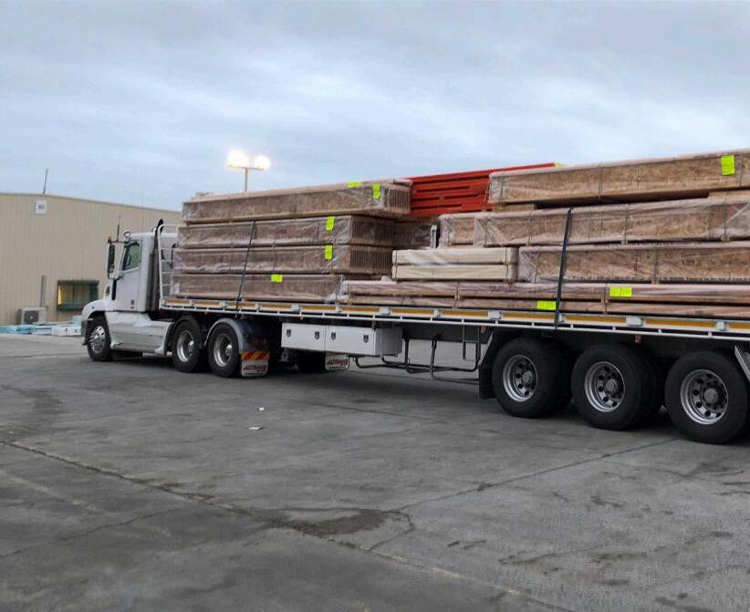
3. Unload products carefully. When lifting support the bundles to reduce excessive bowing. Individual products shall be handled in a manner which prevents physical damage during measuring, cutting, erection, etc. ITI Spec Joist (SJI) I-Joistss shall be handled vertically and not flat wise
4. Keep products stored in wrapped and strapped bundles, stacked no more than 3m high. Support and separate bundles with 45mmx90mm (or larger) gluts spaced no more than 3m apart. Keep gluts in line vertically
5. Product shall not be stored in contact with the ground, or have prolonged exposure to the weather
6. Use forklifts and cranes carefully to avoid damaging products
7. Do not use a visually damaged product. Call your local ITI Spec Joist (SJI) I-Joistss Products distributor for assistance when damaged products are encountered
8. For satisfactory performance, ITI Spec Joist (SJI) I-Joistss Products shall be used under dry, covered and well-ventilated interior conditions in which the equivalent moisture content in the timber will not exceed 16%
Product Code Description ITI Spec Joist (SJI) I-Joists H2-F Treated (South of the Tropic of Capricorn)
SJI200X045H2S 200x45 ITI Spec Joist (SJI) (I Joist) H2S Treated
SJI240X045H2S 240x45 ITI Spec Joist (SJI) (I Joist) H2S Treated
SJI240X069H2S 240x69 ITI Spec Joist (SJI) (I Joist) H2S Treated
SJI240X096H2S 240x96 ITI Spec Joist (SJI) (I Joist) H2S Treated
SJI300X045H2S 300x45 ITI Spec Joist (SJI) (I Joist) H2S Treated
SJI300X069H2S 300x69 ITI Spec Joist (SJI) (I Joist) H2S Treated
SJI300X096H2S 300x96 ITI Spec Joist (SJI) (I Joist) H2S Treated
SJI360X058H2S 360x58 ITI Spec Joist (SJI) (I Joist) H2S Treated
SJI360X089H2S 360x89 ITI Spec Joist (SJI) (I Joist) H2S Treated
SJI400X058H2S 400x58 ITI Spec Joist (SJI) (I Joist) H2S Treated
SJI400X089H2S 400x89 ITI Spec Joist (SJI) (I Joist) H2S Treated Rim Board, Web Infill & Web Stiffeners