

STRUCTURAL PLY

Feb 2025, V2.0 CONTENTS
General
1 1
1 2 Important Documents Purpose of guide
1.3.
1.4. For more help Skills required
1 5
Structural Ply
2.1. Description
4 1 Health & safety
4 2 Handling & storage Pre-Installation
5 1 Key documents
5 2 Confirm scope
5.3. Tools & other product requirements
5.4. fixings & fasteners
2.2. Scope and limitations Design
3 1 Confirm scope For our warranty
3 2 3 3
3.4. Establish substrate suitability Treated or untreated ply Structural ply uses
3 4 1 Wall bracing element
3 4 2 Ceiling Diaphragm
3.4.3. Flooring Diaphragm
3 4 4 Roof & Deck substrate
3 4 5 Flooring
3.5. Other uses
3.5.1. Internal lining
3 5 2 Soffit lining
5.5.
5.6. Specific Use Installation Requirements Cut sheets Predrill pilot holes
6 1
6 2 Wall bracing
6.3. Ceiling Diaphragm 6 4 Floor diaphragm
6 5 flooring Check building and substrates
6 6 Roof or deck substrate
6 6 1 Membrane substrate
6.6.2. Roof sarking
6.7. Soffit lining 6.8. Maintenance Finishing
Version 2 0 Feb 2025
1. GENERAL
1.1. PURPOSE OF GUIDE
This guide provides advice on handling, installing and maintaining EziPly CD & DD Structural Ply, EziPly Tongue & Groove Flooring and EziPly Tongue & Groove Roofing (EziPly).
1.2. IMPORTANT
DOCUMENTS
This guide must be read in conjunction with the:
› › EziPly CD & DD Structural Ply EziPly pass™ EziPly Structural Ply warranty.
1.3. SKILLS REQUIRED
To install one of the structural ply products, the installer must, at a minimum, be a competent DIYer
Where one of the structural ply products has been specified by a designer, the designer shall have the appropriate skills, knowledge of the product and access to all relevant technical information (refer to www.iti.net.nz).
Where Restricted Building Work (RBW) applies, the designer or installer must either be a Licensed Building Practitioner (LBP) or be supervised by an LBP with the applicable licence.
1.4. FOR MORE HELP
Technical assistance is available at info@iti net nz
While all reasonable efforts have been made to ensure the accuracy of information provided, this is a guide only, and it may be subject to change
1.5. FOR OUR WARRANTY
Refer to www.iti.net.nz
Version 2 0 Feb 2025
2. STRUCTURAL PLY
2.1. DESCRIPTION
EziPly is manufactured to AS/NZS 22691 from FSC certified radiata pine The veneers are glued with an exterior phenol-formaldehyde resin The sheets are supplied with a clean face and with solid knots and minor filling Sheets are supplied untreated or treated to Hazard Class, H3. EziPly CD and DD Structural Ply
› length (mm) 2400, 2700
› width (mm) 1200
› thickness (mm) 7, 9, 12, 15,18
EziPly Tongue and Groove Ply Flooring is available in a tongue and groove profile of:
› length (mm) 2400
› width (mm) 1200
› thickness (mm) 18.
EziPly Tongue and Groove Ply Roofing is available in a tongue and groove profile of:
› length (mm) 2700 › width (mm) 1200 › thickness (mm) 15.
ITI NZ supply EziPly Ply for use as:
› a wall bracing element
› floor or ceiling diaphragm
› flooring
› › deck or roof substrate internal wall panelling
› ceiling and soffit linings or
› crafts, general construction and formwork.
EziPly CD Structural Ply is intended for use where appearance is important EziPly DD Structural Ply is intended for uses where the appearance is not as important
EziPly Tongue & Groove Ply Flooring EziPly Tongue & Groove Ply Roofing is intended for use as flooring or a deck or roof substrate
2.2. SCOPE AND LIMITATIONS
For scope of use, limitations, conditions and statement of building code compliance, refer to the EziPly pass™
1 Wherever a standard is referenced it should be taken to read as the standard year cited and modified by the applicable acceptable solution or verification method.
3. DESIGN
3.1. CONFIRM SCOPE
Ensure the project falls within the allowed scope and limitations for the intended use, in particular suitability of the building, treatment requirements and the structural framing support.
3.2. ESTABLISH SUBSTRATE SUITABILITY
Where used as a wall bracing element, ceiling diaphragm, flooring and deck or roof substrate the designer must ensure that the substrate to which the ply is to be fixed is suitable for the intended building work.
3.3. TREATED OR UNTREATED PLY
Ensure that where untreated ply is to be specified that it is in accordance with NZS 3602 Table 1, 2 and 3
Ref no. Wood based building components
1C 2 Plywood sheet bracing
1C.3 Interior flooring, suspended ground floors
1D.1
1D.4
1D 9
1E 6
1E.7
Roofsarking&framingnot protectedfromsolardriven moisturethroughabsorbent claddingmaterials
Roof valley boards and boards supporting flashing or box gutter s, flashings to roof penetrations and upstands to decks
Sheetmaterialproviding wallbracing
Internalwallbracing
Interiorflooring
3 1, 3 2 All interior finishing Shelves
Plywood Plywood Plywood
Plywood Plywood Plywood Radiata pine Plywood
Version 2 0 Feb 2025
3.4.
3.4.1.
STRUCTURAL PLY USES
Wall bracing element
Where used as a wall bracing element, the design and specification require the following:
Sheet size 2400mm x 1200mm x 7mm thick only
› Framing 90mm x 45mm at 400mm, 600mm and 1200mm
› › › H1 2 SG8 framing
M12 bottom plate hold down GIB Handibrac® at brace ends
Wall bracing calculation is based on 2400mm sheet height For greater heights refer to NZS 3604, clause 8 3 1 3 for adjustment
The sheets:
› Are fixed on one face only
› Must be fixed vertically
› Must be nailed or screwed at 150mm centres around the perimeter and be a minimum of 7mm from the edge of each panel and 300mm centres on the middle studs
Fixings are as follows:
› Fixings to be durable in accordance with Table 4.1 NZS 3604.
› Fixing sizes are 50mm x 2 8mm galvanised flathead clouts or 8g x 30mm, galvanised or stainless steel screws
› Nails must be fixed in the centre point of the studs There is no need for nails or screws on nogs or dwangs
Brace width Thickness (mm)
600mm (mm) 7 0
Stud centres
Studs at 600mm centres, no nogs Studs at 400mm centres, no nogs Studs at 600mm centres, no nogs
Note: BU/m value as limited by the ultimate load capacity
3.4.2. Ceiling Diaphragm
86
Ensure EziPly ply is specified in accordance with section 13 5, NZS 3604 or specifically designed to NZS 3603:1993.
3.4.3. Flooring Diaphragm
Ensure EziPly ply is specified in accordance with section 7 3, NZS 3604:2011 or specifically designed to NZS 3603:1993.
3.4.4. Roof & Deck substrate
Where EziPly ply is to be used as a roof sarking, ensure specification is to section 10.4.4, NZS 3604 or specifically designed.
3.4.5. Flooring
Ensure specification is to paragraph 7 2 3 5, NZS 3604 BU/m (EQ) Hold-down method
M12 Hold down bolts to GIB
HandiBrac® and to bottom plate
M12 Hold down bolts to GIB
HandiBrac® and to bottom plate
M12 Hold down bolts to GIB
HandiBrac® and to bottom plate brackets
Where EziPly ply is to be used as a substrate under a membrane, ensure specification is in accordance with paragraph Fig. 8A and paragraphs 5.3 and 8.5.5.1 E2/AS1or E2/AS4.
Version 2 0 Feb 2025
3.5.
3.5.1. OTHER
USES
Internal lining
Where used as a non-structural wall lining, there are no specific requirements for fastening types or spacings
Where used as a structural internal wall lining element, plywood must be fixed in accordance with paragraph 3.4.1 of this guide
For ceiling diaphragms refer to paragraph 3.4.2 of this guide.
3.5.2. Soffit lining
Ensure ply is specified in accordance with paragraph Fig. 8A and paragraph 5.3, E2/AS1 or E2/AS4.
4. PRE-INSTALLATION
4.1.
HEALTH & SAFETY
Take all necessary steps to ensure your safety and the safety of others:
› ensure adequate ventilation or mechanical dust extraction when cutting or drilling
› › › › › ensure the sheets are well supported when cutting wear appropriate safety equipment, including clothing, footwear and safety glasses use all tools in accordance with the relevant instruction manuals clear the work area of any obstructions before work starts ensure edge protection and/or appropriate scaffold is installed where working at height
For further information refer to:
› WorkSafe (7/2018) Small Construction Sites, The Absolutely Essential Health and Safety Toolkit
› WorkSafe. (12/2016) Health and Safety at Work, Quick Reference Guide.
4.2.
HANDLING & STORAGE
Take care when transporting, handling and storing EziPly ply to avoid damaging the sheets
Unload sheets by hand and carry on edge If unloading mechanically, ensure there is a minimum of two well-spaced suppor ts or suppor ted with a pallet to avoid excessive bending or sagging A spreader bar may be needed when using a crane or hiab
If stored on-site, stack sheets flat on a dry surface and at least 150mm off the ground. Cover the sheets. Ensure the area where the sheets are stored is dry, well-ventilated, out of direct sunlight and away from any heat source .

Version 2 0 Feb 2025
5. PRE-INSTALLATION
5.1. KEY DOCUMENTS
Refer to the building consent documentation where applicable, the pass™ and this document
5.2. CONFIRM SCOPE
Ensure the project falls within the allowed scope and limitations for the intended use, in particular suitability of the building, treatment requirements and the structural framing support
5.3. TOOLS & OTHER PRODUCT REQUIREMENTS
Use the following tools:
› fine-tooth hand saw or power saw
› › › › › › jig saw plane drill pin gun sandpaper hole saw and speed bits
› moisture meter (where exposed to moist conditions).
Use the following products:
› adhesives (compatible with the specified treatment hazard class)
› fixings (refer to section 5.4)
› fillers.
5.4. FIXINGS & FASTENERS
Fixings are to be in accordance with the building consent or as described under the specific use: 50mm x 2.8 mm F/H nails or 8g x 30mm screws for structural and general installations.
Note:
› Where the ply is treated all fasteners must be a minimum of hot-dipped galvanised, stainless steel or silicon bronze
› Where the ply is untreated then fixings may also include zinc-plated finishing pins.
› Fixing material selection is to be in accordance with NZS 3604:2011, section 4.
5.5. CUT SHEETS
Cut sheets using a fine-tooth hand or power skill saw Erase the edge using a plane or 120–150 grit sandpaper over a block
5.6. PREDRILL PILOT HOLES
Where sheets are to be fixed with screws, predrill 2 0mm pilot holes to prevent splitting the sheets edges Drill the holes approximately 2–3mm deeper than the screw depth Do not overtighten screws as it will reduce their holding strength
Version 2 0 Feb 2025
6. SPECIFIC USE INSTALLATION REQUIREMENTS
6.1.
CHECK BUILDING AND SUBSTRATES
› Ensure that the timber framing, to which the structural ply is to be fixed, has a moisture content < 18 %
› For an internal lining, establish the building is fully weathertight
› For a roof and deck substrate, ensure the joists and rafters are spaced correctly and the specified slope meets the applicable roof and deck cladding requirements
› For wall bracing, ceiling or floor diaphragm, ensure studs are plumb, true and spaced correctly
6.2. WALL BRACING
Refertoplansandspecificationsforbracinglocationandinstallationrequirements
Note:
› sheetsarefixedononefaceonly
› sheetheightis2400mmunlessspecifiedbythedesigner
› sheetsmustbefixedvertically
Sheetsmustbefixed
› with50x28mmgalvanisedsteelnailsor8gx30mmscrewsat150mmcentresaroundtheperimeter, a minimum of 7mm from edge and 50 x 2.8mm galvanised steel nails or 8g x30 mm screws at 300mm centres to middle studs
› with GIB HandiBrac® to each end Ensure the GIB HandiBrac® is placed in the corner of each bracing sheet

› so the embedment of fixings does not exceed the first veneer layer

6.3.
CEILING DIAPHRAGM
Install in accordance with NZS 3604 (section 13 5) or as per the specific design documented in the building consent documentation This includes the required lengths and widths of the diaphragm, the shape of the diaphragm, sheet sizes, battens and linings. Sheets must be fixed
› with 50 x 2 8mm galvanised steel nails or 8g x 30mm screws at 150mm centres around the perimeter, a minimum of 7mm from edge and 50 x 2 8mm galvanised steel nails or 8g x 30mm screws at 300mm centres to middle studs
› so the embedment of fixings does not exceed the first veneer layer.
Version 2 0 Feb 2025
6.4. FLOOR DIAPHRAGM
Install in accordance with NZS 3604 (section 7 3) or as per the specific design documented in the building consent documentation This includes the required lengths and widths of the diaphragm, sheet sizes, supports and connections Sheets must be fixed
› with 50 x 2 8mm galvanised steel nails at 150mm centres around the perimeter, a minimum of 7mm from edge and 50 x 2 8mm galvanised steel nails at 300mm centres to middle joists
› so the embedment of fixings does not exceed the first veneer layer.
6.5. FLOORING
Install in accordance with Section 7.2.3.5 NZS 3604 or as per the specific design documented in the building consent documentation. Select the appropriate joist spacing and sheet thickness for the applicable floor load. Ensure the sheets are laid perpendicular to the joists in a staggered pattern. Allow 2–3mm expansion gap between sheet joints allowing for movement. All edges must be supported. Sheets must be fixed;
› with 50 x 2.8mm ring shank galvanised steel nails at 150mm centres around the perimeter, a minimum of 7mm from edge and 50 x 2 8mm galvanised steel nails at 300mm centres to middle stud
› so the embedment of fixings does not exceed the first veneer layer


Brace Sheet Fixing
Typical ITI NZ Structural Plywood
Typical ITI NZ Structural Plywood Tongue & Groove Joists
Rafters
All Joists over Timber Support
Structural Plywood
Edge Tongue
Standard Structural Plywood
Edge Groove
50 x 28mm Galvanised Steel Nails OR 8 g x 30mm Galvanised Sure-Fix Screws
Nogs
Version 2 0 Feb 2025
6.6.
6.6.1.
ROOF OR DECK SUBSTRATE
Membrane substrate
Install in accordance with Paragraph 8 5 5 1
E2/AS1 or E2/AS4 or as per the specific design documented in the building consent documentation.
For a roof substrate, ensure the sheets are laid perpendicular to the joists in a staggered pattern and the sheet ends are supported over timber. Allow 2–3mm gap between sheet joints for movement. Maximum rafter spacings will depend on the selected thickness of the Structural Ply. For membrane roofs and decks, all fixings to be flush or countersunk with the EziPly Ply surface. Remove all sharp sheet edges that could damage the membrane.
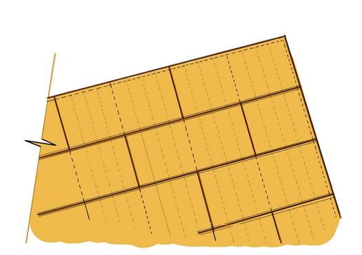
MaximumSpacing@400mmFixings@maxiumum150mmtoall edgesand300mmtoCentralJoists
Typical sheet layout
Membrane installer to ensure the moisture content of the EziPly Ply meets the membrane manufacturer’s specification prior to installation. The maximum spacing of support timbers shall be no less than 400 mm. Sheet edges must have a minimum chamfer of 5mm
Check the surface for joist deflection and adjust or pack where possible to maintain a flat, even surface
6.6.2.
Roof sarking
Install in accordance with section 10 4 4, NZS 3604 or as per the specific design documented in the building consent documentation Ensure sheets are fixed directly to rafters or truss top chords not less than 10mm from sheet edges
Internal lining
Install vertically or horizontally to wall framing as a wall lining Where used as a ceiling lining, stagger sheet joints, ensuring that all joints are over support framing
Where used as a non-structural wall lining, there are no specific requirements for fastening types or spacings
However, where exposed to water splash galvanised steel or stainless steel, fastenings are recommended.
Where used as a structural internal wall lining element, plywood must be fixed in accordance with paragraph 6.2 of this guide For ceiling diaphragms, refer to paragraph 6 3 of this guide
6.7. SOFFIT LINING
Install in accordance with Par agr aphs 5 3 and Fig 8A of E2/AS1 or E2/AS4 or as per the specific design documented in the building consent documentation
Sheets must be fixed
› with 50 x 2 8mm F/H galvanised steel nails at 300mm maximum centres through the outriggers or sprockets, with the outer edge supported by the fascia
› so the embedment of fixings does not exceed the first veneer layer
6.8.
FINISHING
Once installed, fill all visible screw, nail or staple holes with a flexible grade wood filler and then lightly sand
Finish the sheets with polyurethane or paint Use three coats consisting of a primer and two topcoats Sand the surface after each coat with 280–320 grit sandpaper
As a deck substrate, prior to the installation of the waterproof layer, the CD Ply must be prepared in accordance with the relevant waterproof supplier’s requirements and E2/AS1
Tongue Joint at long edge
Eziply Toungue & Groove ply flooring and EziPly Tongue & Groove Roofing
Version 2 0 Feb 2025
7. MAINTENANCE
Under normal conditions, EziPly Ply will need no maintenance as long as finished layer or coating has been maintained.
Regular inspections should be carried out to check the sheets have not been damaged by humidity or moisture. If there is evidence of swelling to bracing sheets, they must be removed and replaced with new ones.
If water damage does occur to an area where EziPly ply has been used, first remove the finished layer or coating. Allow for the area to dry thoroughly before you replace the ply if necessary and reinstate the finishing.
In the unlikely event the ply is damaged it can be repaired by patching or stopping with a suitable interior grade filler. For larger holes, or if the ply is being used as a bracing element sheet replacement is required.
