


Focus on innovation and sustainable building products.
Byggma Group are a multidivisional building products manufacturer based in the Nordic region of Europe with 8 manufacturing sites spread across Norway and Sweden.
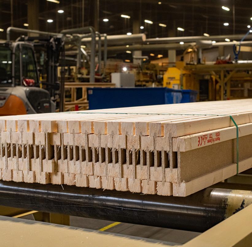
Lightweight Swedish I-Joist. Swelite by Byggma Group.
Greater environmental awareness makes it more important than ever to choose building materials that are sustainable and environmentally friendly. The composite I-profile means less raw material is required and up to 80% of the tree’s fibre can be used for production of Swelite I-Joist.
The web material is manufactured using small diameter logs or logs which would otherwise not be suitable for producing larger structural timber sections. The premium grade flange material is created by recovering high quality short lengths of timber from local saw mills which are then finger joined together using a high strength adhesive.
Byggma Group’s Swelite I-Joists are available with PEFC chain of custody
Swelite I-Joists have a number of economic and technical advantages over alternative materials.
Long. Standard lengths up to 12 m.
Strong. Products are made from carefully selected construction timber and special board materials.
Lightweight. Lower weight when compared to ordinary structural timber or open web floor trusses makes for an easy-to-handle product speeding up installation time.
Straight. Minimal skew and shrinkage when exposed to moisture through glued components.
Easy drilling for installations. Easy execution of installations by smooth drilling in the thin 10mm web. Making holes in the web of Swelite I-Joist is quick and easy.
Consistent. Products are machine made, not man made, which makes each piece consistent with the next.
Type-approved and controlled. Swelite I-Joists are type-approved both in any countries. Manufacturing control takes place through routine production testing and an accredited control body.
ISO certified. Design and manufacturing is certified according to ISO 9001 Quality Management and ISO 14001 Environmental Management Systems.


Growth through premier brands and innovation
Since establishment in 1987 in Five Dock, NSW, Independent Timber Importers has been on a mission to redefine the timber industry wholesale/distribution landscape. ITI has worked closely with industry suppliers, customers and associations to promote the strength, beauty and environmental benefits of using timber. At the same time ITI redefined the role of the wholesaler with its distribution and service models. With its large investments in distribution centres, product development, people and service standards; in early 2002 ITI dropped the name Independent Timber Importers and replaced this with ITI and introduced the new logo with the “Innovative Timber Ideas” phrase which more accurately describes the attitude of the company.
Today ITI consists of 9 distribution sites across Australia with over 130,000m2 of undercover storage, a state of the art re-manufacturing, treating and priming plant in Chile, an office in Indonesia, 3 distribution locations in New Zealand and growing sales in the USA.
True to its name, the success of ITI lies in its commitment to innovation in both service and product development. This commitment has led to premier brands such as Design Pine, EziTrim Plus and Spec Beam along with the distribution of market leading products such as Pacific Woodtech, Metsa Wood, Weathertex and Modwood. ITI has also led the way with service standards winning countless industry awards for its service.
ITI Engineered Wood Products
ITI source Engineered Wood Products from leading manufacturers to ensure the needs of building designers through to the end user are met with the best available product.
ITI Engineered Wood Products offering is comprised of 3 major products with each intended on complimenting the next. Laminated Veneer Lumber (LVL), I-Joists and Glue Laminated Timber Beams (GLT). These products along with innovated construction details and dedicated support staff provide a platform which set ITI Engineered Wood Products apart from the rest.

Single Member Design Software
Available from ITI Australia is ITI Design Spec. A single member design software developed to assist industry professional with the specification of ITI’s vast range of structural timber products. Free licences are available to suit builders, timber merchants, frame & truss professionals and engineers. Head to www.itiaustralia.com.au to download for free.

SWELITE I-Joist Product Specification
Swelite I-Joists are comprised of lightweight, 47mm thick, finger jointed pine top and bottom flanges tied together using either a high performance particle board web or an Oriented Standard Board (OSB) web.
TREATMENT
Swelite I-Joists are available in Queensland and New South Wales with a post manufacture H2 Blue Treatment suitable for below the tropic of Capricorn. Suitable for indoor above ground protection against Termites and Borer.
Bifenthrin is a cost effective water-borne treatment applied by flooding the I-Joists in a treatment tank. It is both a termite deterrent and a digestive insecticide. Bifenthrin treated I-Joists will be identifiable by a blue tint created by a dye which is added into the treatment liquid.
It is recommended that all exposed cuts are resealed, or abut a treated member with an equal or greater level of treatment, however the repellent benefits of Bifenthrin treatment allow cross-cut faces to be left exposed.
Bifenthrin treatment does not affect the adhesion attributes of the timber or the adhesives.
The same precautions apply to Bifenthrin treated I-Joists as other treated timbers; do not burn offcuts; wear gloves when handling treated timber; wear a mask and goggles when cutting; clean up residual dispose of saw dust; and wash exposed clothing separately.
Characteristic values for Swelite I-Joists have been evaluated by an appropriately qualified engineer and converted to Australian Limit State Design using internationally recognized evaluation reports, physical testing data and relevant Australian Standards. Reference documents include:
Referenced Standards & Guides:
• AS 4063.1: Characterisation of structural timber – Test methods
• AS 4063.2: Characterisation of structural timber – Determination of Characteristic Values
• ETAG 011: Guideline for European Technical Approval of Light Composite Wood-Based Beams & Columns
• ETOA TR 002: Test Methods for Light composite Wood-Based Beams & Columns
• EN 12369-1: Characteristic Values – Structural Panel Products
• EN 338: Structural Timber – Strength Classes
Evaluations & Reports:
• ETA 12/0018 European Technical Assessment for Light composite Wood-Based Beams & Columns
Issued by: RISE Research Institutes of Sweden AB
• Production Control Testing Data of Assembled Product
Dated between 18th September 2018 and 20th May 2022
Quality Control Governance:
• 0402 – CPR – 0933/00 Certificate of Consistency of Performance
Issued by: SP Technical Research Institute of Sweden
• ISO 9001 Quality Management Systems
Issued by: RISE Research Institutes of Sweden AB
• ISO 14001 Environmental Management Systems
Issued by: RISE Research Institutes of Sweden AB
Notes:
1. Swelite I-Joists shall be designed for dry-use conditions only. Dry-use applies to products installed in dry, covered and well ventilated interior, conditions in which the equivalent moisture content in timber will not exceed 16%.
2. All values may be be adjusted for load duration (k1) as permitted in AS1720.1 excluding EI, k and verticle load capacity.
3. Deflection calculations shall include both bending and shear deformations.
Deflection for a simple span, uniform load: = ∆ = 5wL4 + wL2 384EI k
Where:
∆ = Deflection (mm)
EI = bending stiffness (from table)
k = Coefficient of Shear Deflection (from Table)
w = uniform load (kN/m)
L = design span (mm)
FLOORS JOISTS & BLOCKING REQUIREMENTS
Floor joists are members which run parallel in series designed to support floor loads. The spacing of floor joists shall be such that it meets the requirements of the supported flooring / floor sheet.
Common Blocking Size Requirements
I-Joist or Solid Timber
Common Studs
Full Height Blocking min. 35mm Thick
Blocking Type
1 Intermittent blocking over external support at start / end of joist run
2 Intermittent blocking over internal support at start / end of joist run
3 Intermittent blocking over external support at 1800mm centres
4 Continuous Blocking to cantilevered joists
5 Rimboard / Fascia Beam to ends of cantilevered joist Maximum1800mmcentres
Blocking to Concentrated Loads
Concentrated Load
Bottom Plate
Floor Joists
Support Framing
Blocking is required to provide resistance to lateral loads applied to the floor diaphragm, transfer concentrated loads down into the support structure. Unlike Common Blocking; Concentrated Load Blocking needs to be full height and a minimum of 35mm thick.
Rimboard
Rimboard can be used as a form of blocking and bracing to floor & roof framing systems. Rimboard also has the ability to transfer some horizontal and verticle loads through the floor diaphram. Refer to Details A1 and C1.
Web Infill is used to re-inforce the I-Joist should augmentation be required, such as shower set downs, or to repair incorrectly cut members, such as misplaced plumbing penetrations.
Fix 1x 75x3.05 nail to each top and bottom flange
Connection of flooring sheets to rimboard per flooring manufacturers requirements
Rimboard to top plate via 75x3.05 nails skewed at 150mm centres
Swelite I-Joist may be used as a perimeter joist under the provision that any imposed loads greater than those nominated in the adjacent table have additional transfer / squeeze blocks installed. Refer to details A10 and B3.
WEB STIFFENING REQUIREMENTS
Web stiffeners are required to be fitted to both sides of I-Joists where:
• Additional non uniform loads are applied to the top of I-Joists (refer to details A10 & B7);
• The bottom flange of the I-Joists are notched to accommodate steel or LVSIA connections (refer to detail E9);
• Additional support bearing strength is required (Refer to detail B1 & H1); or
• Joist hangers do not restrain the top flange by more than 20mm (Refer to detail E3)
Web stiffeners required under load bearing walls
30mm minimum end support length required
Web stiffeners are required where joists hangers do not restrain the top flanges by a minimum of 20mm
63mm minimum intermediate support length required
Web Stiffener Requirements for use with Joist Connectors
Notes:
1. Where Web Stiffeners are required for use with shallow joist hangers the thickness is required to be that of the distance between the web and the outside of the flange.
2. Web stiffeners shall be cut to fit between the flanges of Swelite I-Joist, leaving a minimum 2mm and a maximum of 10mm gap.
3. Web stiffeners shall be cut from particle board, plywood or OSB Rim Board.
4. Web stiffeners may be comprised of up to 2 sections of timber i.e., 1x 18mm + 1x 25mm thick plywood, however builders adhesive must be applied between the sections.
5. Web stiffeners shall be a minimum width of 50mm or the depth of the joist hanger seat / support.
Web Stiffener Requirements for Improving Bearing Strenth
Notes:
1. Refer to page 7 for more information on the k1 load duration factor
2. Web stiffener length to be a minimum length of the Joist Height / 2
3. Web stiffeners shall be installed in pairs – one to each side of the web.
4. Web stiffeners used to improve bearing strength are not required to finish flush with the outside edge of the flanges.
5. Web stiffeners shall be cut to fit between the flanges of Swelite I-Joist, leaving a 2mm gap.
6. Web stiffeners shall be cut from plywood, LVL or OSB Rim Board. 35mm timber is permissible.
7. Reaction Capacity is for instantaneous load duration and shall be adjusted using k1.
8. Bearing capacity may be further limited by the bearing strength of the support material. The bearing capacity of a timber support is based on the species of the supporting timber i.e Radiata Pine (12 MPa).
Additional Considerations:
9. End Reation value shall not exceed the V value as indicated on the Design Values Table from page 5 of this document for the corresponding joist size.
10. Intermediate Reation value shall not exceed 2x the V value as indicated on the Design Values Table from page 5 of this document for the corresponding joist size.
Notes:
1. Web Stiffeners required to intermediate support
Suggested spans: Span / 500 or 2mm of DL deflection per 1 m of span up to a maximum of 10mm
SPAN TYPES
Single Span
Continuous Span
A continuous span only applies when the smaller of the spans is no less than half the larger span. Where this does not apply; both spans are to be treated as single spans or further design analysis is required. Measure spans between internal faces of the supports.
In wind regions up to N3, nominal fixing of joists to support is 2/75x3.05 Nails skewed through bottom flange of the I-Joist. Refer to Detail B1. Where uplift is present, or joists are installed in higher wind regions refer to AS1684 for additional tie-down requirements.
HOLES IN SWELITE I-Joist
Consider clusters of holes as a single larger hole
I-JOISTS
Minimum distance to:
h1 = A1
h2 = Larger of A2, h1 x2 or h2 x2 measued from h1; and Larger of A3, h2 x2 or h3 x2 measued from h3
h3 = Larger of A3, h2 x2 or h3 x2 measued from h2; and Larger of A2, h3 x2 or h4 x2 measued from h4
h4 = A1
Where:
A1 = Minimum distance from support per relevant Swelite I-Joist Distance to Hole tables
A2 = Minimum distance from support for relevant Swelite I-Joist Distance to Hole tables
A3 = Minimum distance from support for relevant Swelite I-Joist Distance to Hole tables
h1 = longest side of rectangular hole or diameter of round role
h2 = longest side of rectangular hole or diameter or round hole
To use:
1. Minimum allowable span to be 2x the distance from hole location from support per tables
2. Select the depth of I-Joist in which holes will be penetrated
3. Select the row which corresponds to the span. For spans which fall between those listed round up to the larger span
4. Select the column which corresponds to the hole size. Always round the hole size up. Rectangular holes not listed may be assessed as 0.75 the diameter of a round hole for the largest side of the rectangle
5. The intersecting value is the nearest allowable distance from the inside face of the support to the nearest edge of the hole
6. Double check the location by cross referencing the allowable distance of the opposing support
7. When multiple holes are required always consider placing the smallest holes closest to the support
Notes:
1. CUT HOLES CAREFULLY. DO NOT OVER CUT HOLES
2. DO NOT CUT THE FLANGES OF THE I-JOISTS
3. Check allowable hole locations from both I-Joists supports
4. Holes may be located within the full depth of the web provided there is a minimum of a 2mm gap from the bottom of the hole to the flange
5. No holes are to be cut into a cantilever
6. Multiple holes may be spaced closer than specified however the assessment should be made for a larger hole whereby the smaller holes are enclosed within the larger hole
7. Hole locations are only valid on joists supporting uniformly distributed loads only and where the joists are spanning no greater than the allowable maximum span
SWELITE I-Joist DISTANCE TO HOLES - 300mm
A1
LVL OR PLYWOOD RIMBOARD (I-Joist)
Fix flooring to rimboard by driving 2.80x65mm framing nails at 150mm centres
Fix rimboard to each I-Joist by driving 1x 2.80x75mm framing nail into each flange
A3
Same depth as I-Joist
blocking over support 1 block at 1800mm centres (I-Joists)
Fix flooring to each I-Joist block by driving 2.80x65mm framing nails at 150mm centres
Same depth as I-Joist
Fix rimboard to top plate by skew nailing 2.80x65mm framing nails at 150mm centres
A5 continuous blocking over supports (I-JOISTS)
Fix flooring to each I-Joist block by driving 2.80x65mm framing nails at 150mm centres
Fix blocking to top plate by skew nailing 2.80x65mm framing nails at 150mm centres
Blocks required at both ends of joist runs
A7 BALCONY LEDGER CONNECTION
Min. 35mm Rimboard
Same depth as I-Joist
Fix blocking to top plate by skew nailing 2.80x65mm framing nails at 150mm centres
A8 UNSUPPORTED LVL PERIMETER JOIST
Fix flooring to the top of the LVL using 65x2.50 nails at 150mm centres
Maximim
A9
Required flashing under cladding and over balcony ledger
H3 Treated 45mm Ledger
Required flashing under balcony ledger and providing the required protection to support structure
LVL SUPPORTED OVER EXTERNAL SUPPORT
Fix flooring to the top of the LVL using 65x2.50
centres
A10 I-Joist SUPPORTED over external support
Fix flooring to the top flange of the I-Joist using 65x2.50 nails at 150mm centres
B1 I-Joist support Nailing
Fit Web Stiffeners to both side of the I-Joist under point loads from openings and trusses
Skew Nail the bottom flange of the I-Joist to the top plate using 65x2.50 nails at 150mm centres
B3 squash blocks to ends of i-joist
Concentrated loads from openings or roof framing
1-2mm deeper than I-Joist
90x35 Squeeze blocks fitted to both sides of I-Joists 2.80x65mm framing nail to to each I-Joist flange 2.80x65mm framing nail skewed to top plate
b5 flooring supported against deep perimeter joist
Minimum of 35mm clearance required from end of I-Joist
Fix to support by nailing 75x3.05 nails through the bottom flange on either side of the I-Joist
b4 i-joists supporting offset load bearing wall
Blocking required to supports of I-Joists (Not Shown)
Install Web Stiffeners to both sides of I-Joist under point loads from load bearing wall over
b6 FRAME OVERHANG TO FLOOR MEMBERS
Structural pine fixing plate to support flooring sheet
75x35mm min. deep structural timber plate fixed to the side of the deep perimeter joists via 75x3.08 framing nails at 150mm centres. Flooring installed per manufacturers requirements.
10mm maximum allowable frame overhang to floor member. Position frame overhang to outside of floor to ensure fixing is available for skirting boards.
c3 BALCONY CANTILEVER (I-JOISTS)
Continuous blocking same depth as balcony joists
Web stiffening fitted to both sides of I-Joists using building adhesive and 2 rows of nails staggered at 150mm centres to both sides
Fix balcony joists using 2 rows of 75x3.05mm nails at 150mm centres. Bottom row of nails to be fixed into I-Joist bottom flange
c1 standard cantilever (I-Joist)
Rimboard to be fitted to ends of cantilever using a 75x3.05mm nail into each top and bottom flange.
Continuous blocking to be installed to joists over the cantilevers support
D2 SETDOWN FLOOR
Non Load Bearing Wall
Supported on upper floor
90x45 Pine Packer I-Joist or LVL Floor Joists
Subject to the structural adequacy of the floor framing members. Attach Fixing Plate to side of LVL with 75x3.08 nails at 150m ctrs.
Cantilevered balcony joists to be a minimum of 2/3 the depth of the attached joists
Rimboard / Fascia to ends of balcony joists
1.2 metres maximum
2x Cantilever Span 600mm minimum
D1 SETDOWN FLOOR 60mm set down i-joist
Non Load Bearing Wall
Supported on lower floor
60x45 Pine Packer
90mm wide I-Joist
Subject to the structural adequacy of the floor framing members. Suitable for 300/240mm and 360/300mm floor joist depths.
D8 balcony to floor blocking perpendiculAr
Full height solid blocking set back min. 30mm from outside support
Flashing / water proofing to timber members designed by others 2x 70x3.08 nails fixed through blocking into Balcony Joists. Nominal fixing to floor and balcony joists required.
e2 face mount hanger i-joist to timber connection
e3 shallow face mount hanger i-joist to timber connection
Web stiffeners are to be fitted to both sides of I-Joist where hangers do not restrain the top flange by 20mm min.
3.75x38mm nails are to be fitted to every round hole in hanger.
e6
FACE mount hanger i-jOIST TO STEEL flange CONNECTION
Pair of M12 Bolts to be fitted at location of packing blocks with 60mm minimum edge clearance to fixing / waling plate. Bolts and packing blocks to be located at 900mm centres, at edges and at point load locations.
Packing Blocks may be positioned vertically or horizontally within the steel
3.75x38mm nails are to be fitted to every round hole in hanger
Packing blocks to be 90mm wide minimum and JD4 or better.
E8 NOTCHED I-JOIST TO STEEL
Plywood or Structural Pine Web Stiffers to be installed either side of I-Joist Web per detail W1 3mm to 25mm gap to top of Web Stiffener and underside of flange recommended
Maximum 13mm notch to bottom flange
Hanger required to be a minimum of 2/3 the depth of the supported member
3.75x38mm nails are to be fitted to every round hole in hanger.
E7 top mount hanger i-joist to steel connection
45mm Fixing plate attached to steel via M12 bolts staggered at 600mm centres
3.75x38mm nails are to be fitted to every round hole in hanger
Leave 3mm gap between I-Joist and steel to prevent squeaks.
E9 75x50x5 UA SEAT
5mm x 45mm notch to bottom flange
Do not over cut
Do not cut flange
Creeper Connector to 1 side of I-Joist for skewed connection
1x 10x30mm Screw
Maximum half depth of I-Joists
Blocking required between floor joists per details A3 or A5.
1x Mini Grip (or Similar) fixed to either side of I-Joist for perpendicular connection
Not acceptable for use with SJ-20 Series I-Joists. 75x50x5UA fixed to supporting beam via 4x 10gx30mm screws.
E4 FACE mount hanger i-joist to steel web connection
Pair of M12 Bolts to be fitted at 900mm centres. 60mm minimum edge clearance to fixing / waling plate.
3.75x38mm nails are to be fitted to every round hole in hanger.
E5 FACE mount hanger i-joist to steel flange connection
Pair of M12 Bolts to be fitted at location of packing blocks with 60mm minimum edge clearance to fixing / waling plate. Bolts and packing blocks to be located at 900mm centres, at edges and at point load locations.
Packing Blocks may be positioned vertically or horizontally within the steel
3.75x38mm nails are to be fitted to every round hole in hanger
Packing blocks to be 70mm wide minimum and JD4 or better.

I-Joist Hanger Codes
Joist Size Dunning’s Simpson Strong-Tie
240x47 BIH234X50 IUSE239/48
240x70 BIH231X74 IUSE239/73
240x97 BIH230X99 -
255x70 - IUSE239/73
300x47 BIH295X50 IUSE299/48
300x70 BIH283X74 IUSE299/73
300x97 BIH285X99 -
360x70 BIH351X74 IUSE359/73
360x97 BIH338X99 -
400x70 BIH391X74 IUSE399/73

I-Joist
240x47 BITH240X50 ITSE239/48
240x70 BITH240X74 ITSE239/73
240x97 BITH240X99 -
300x47 BITH300X50 ITSE299/48
300x70 BITH300X74 -
300x97 BITH300X99 -
360x70 BITH360X74 ITSE359/73
360x97 BITH360X99 -
400x97 BIH385X99Top
400x70 BITH400X74 -
Dunning’s Dead Load 5.8 4.1 Dead + Floor Live Load 7.0 5.0 Dead + Roof Live Load 7.8 5.6 Dead + Wind 9.0 8.3
NOTES:
2. Use 38x3.75mm Galvanized Nails to holes provided
3. Recommended to use No.6 Type 17 Bugle Head Screw 30mm through hanger into bottom of I-Joist
4. 0.55 kN uplift capacity when 2/ 38x3.75mm Nails fitted to bottom flange of joists via the holes provided
5. Use No.12 Type 17 Screws 30mm to supporting member & No.12 Type 17 Bugle Head Screws 30mm to supported member
6. Only install fixing to predetermined holes in connectors
7. I-Joist Hangers do not provide any tie-down. Where uplift is present additional tied-own provisions are required. Refer to AS1684 for more details
8. I-Joist hangers are to restrain the top flanges of the I-Joist by a minimum of 20mm
9. If I-Joist hangers do not restrain the top flange then web stiffeners are required to be fitted to both sides of the I-Joist web
10. Hangers to be a minimum of 2/3 the depth of the I-Joists
11. Face & Top Mount hangers must not be modified in any way. Hangers will generally allow a skew up to 50 and a slope up to 20
Lower
BRACING WALLS TO FLOOR FRAMING
2x 90x35 shear blocks 140mm minimum length
2/90x35 shear blocks 130mm minimum length
Screw blocks to top plate via 2x 14g 100mm batten screws per block
Refer to table below for fixing requirements
Screw blocks to top plate via 2x 14g 100mm batten screws per block
Refer to table for min. size
Upper Bracing Wall to LVL Joists below - Perpendicular & Parallel - Type (b)
Bolt with square washer
Member as designed
Refer to table for min. width
Upper Bracing Wall to LVL Joists below - Perpendicular & Parallel - Type (c)
Bolt with square washer
Refer to table for min. size
2x Multi Grips per end with 6x 2.8x30mm nails
NOTES:
1. Values based on timber framing with a joint group of JD5 or greater
2. Fixing Blocks to fit snug in between Shear Blocks
3. 14g x100mm Batten Screw based on using 2x 35mm shear blocks through a 35mm top plate. Where wider members are used increase the length of the screw by the same length
4. Floor Joists to be installed and fixed in accordance with appropriate installation guide and AS1684
5. Designs derived from information available in AS1720.1 and AS1684.2
6. Refer to AS1684.2 for more information of bracing types and intermediate fixing detail requirements
7. Where intermediate fixings are required in the form of an M10 bolt at 1200mm centres any of the details shown are acceptable
Min. 35mm bearing required
SHOWER SETDOWN DETAIL
25mm F11 Plywood or E11.7 LVL to both sides of I-Joists
Continuous blocking to inside edge of notch One side only
Packer to support flooring 35mm wide pine to support flooring