


Test standard: Clauses 14 and 22 of AS 1530.8.1:2018
Test sponsor: Wood Modification Technologies Limited
Product: FLAMEfixx® subfloor system
Bushfire attack level (BAL) exposure: 40 kW/m2 Crib class: AA
Job number: FRT20042
Test date: 10 May 2021 Revision: R1.0
Warringtonfire: accredited for compliance with ISO/IEC 17025 – Testing
Test standard: Clauses 14 and 22 of AS 1530.8.1:2018
Job number: FRT20042
Test sponsor: Wood Modification Technologies Limited
Revision: R1.0
1 of 23
Test standard:
Job number: FRT20042
Test sponsor:


Revision: R1.0
This report documents the findings of a simulated bushfire attack – radiant heat and small flaming sources test on elements of construction for buildings undertaken on 10 May 2021 in accordance with clauses 14 and 22 of AS 1530.8.1:2018.
Warringtonfire performed the test at the request of Wood Modification Technologies Limited
Table 1 provides details of the test assembly, and Table 2 provides a summary of the test specimen. A summary of the results is provided in Table 3.
Item Detail
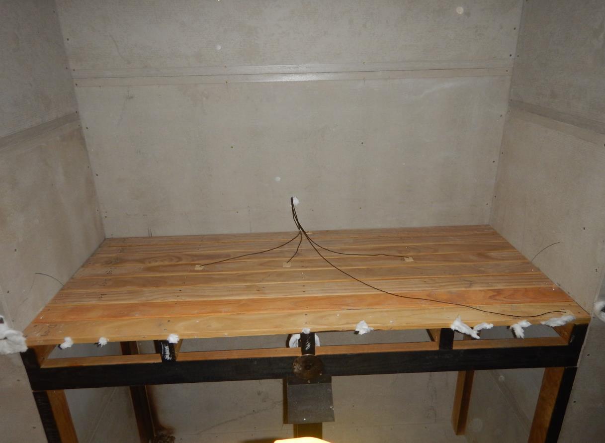
Test specimen
• Six 90 × 45 FLAMEfixx® timber stumps were cut to a length of 1300 mm long. They were located below the four corners of the bearers with an additional stump located mid-width of the front and rear bearers.
• Two 90 × 45 FLAMEfixx® timber bearers were cut to a length of 1800 mm long and were located on top of the stumps.
• Five 90 × 45 FLAMEfixx® timber joists were spaced at 450 mm centres and secured to the top of the timber bearers using 75 mm long framing nails. The nails were shot at an angle through the sides of the joist into the bearers with a nail located either side of each joist
• The 20 mm thick × 140 mm wide FLAMEfixx® decking boards were installed over the top of the joist and laid perpendicular to the joists. The deck boards were secured to the joists using 10g × 65 mm long bugle head Type 17 decking screws. There was a nominal 2 mm gap between each deck board.
Test standard: Clauses 14 and 22 of AS 1530.8.1:2018
Job number: FRT20042
Revision: R1.0
Test sponsor: Wood Modification Technologies Limited Page 3 of 23
Test results
Formation
Sustained flaming for 10 s on the non-fire side
Flaming on the fire-exposed side at the end of the 60 minute test period
Radiant heat flux 365 mm from the non-fire side exceeding 15 kW/m2
Mean and maximum temperature rises greater than 140 K and 180 K
Radiant heat flux 250 mm from the specimen, greater than 3 kW/m2 between 20 min and 60 min
Mean and maximum temperature of internal faces exceeding 250 °C and 300 °C respectively between 20 min and 60 min after commencement of test
Test result
Test standard: Clauses 14 and 22 of AS 1530.8.1:2018
Job number: FRT20042
Test sponsor: Wood Modification Technologies Limited
No failure -
Not applicable -
No failure -
No failure -
Not applicable -
Revision: R1.0
This report documents the findings of a simulated bushfire attack – radiant heat and small flaming sources test on elements of construction for buildings undertaken on 10 May 2021 in accordance with clauses 14 and 22 of AS 1530.8.1:2018.
Warringtonfire performed the test at the request of the test sponsor listed in Table 4
Table 4 Test sponsor details
Test sponsor
Wood Modification Technologies Limited
Address
19 Melanesia Road
Kohimarama Auckland 1071 New Zealand
Table 5 describes the test specimen and lists the schedule of components. These were provided by the test sponsor and surveyed by Warringtonfire.
All measurements were done by Warringtonfire – unless indicated otherwise.
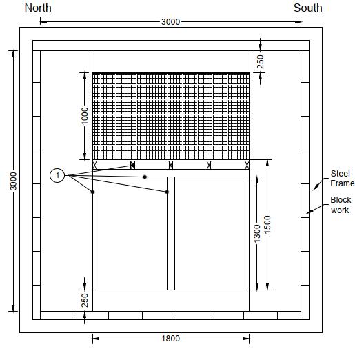
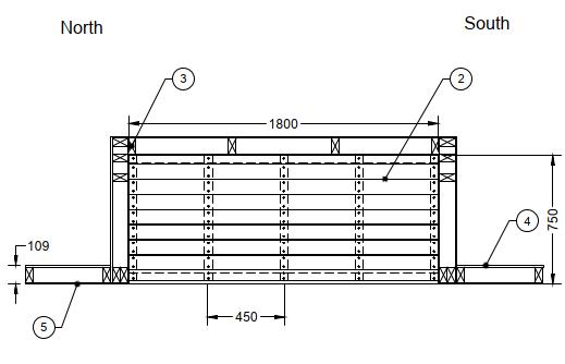
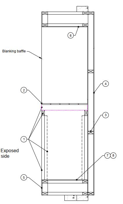
Detailed drawings of the test specimen are provided in Appendix A
Table 5 Schedule of components
Item Description
Sub-floor
1. Item name FLAMEfixx® subfloor system
Material Treated Radiata Pine
Size
90 mm deep × 45 mm wide × 1300 mm high stumps
90 mm high × 45 mm deep × 1800 mm wide bearers
90 mm high × 45 mm wide × 750 mm deep joists
Moisture content Stumps: 13.6%
Bearers: 14.8%
Joists: 13.7%
Fixings
3.06 × 75 mm long bright smooth shank framing nails.
2. Item name FLAMEfixx® deck boards
Material Treated Radiata Pine
Size 20 mm thick × 140 mm wide × 1800 mm long
Density 500 kg/m3
Moisture content 13.4%
Fixings 10g × 65 mm long bugle head Type 17 decking screws
Subfloor Overall size 1800 mm wide × 1500 mm high × 750 mm deep
Installation
• Six 90 × 45 FLAMEfixx® timber stumps (item 1) were cut to a length of 1300 mm long. They were located below the four corners of the bearers with an additional stump located mid-width of the front and rear bearers.
• Two 90 × 45 FLAMEfixx® timber bearers (item 1) were cut to a length of 1800 mm long and were located on top of the stumps.
• Five 90 × 45 FLAMEfixx® timber joists (item 1) were spaced at 450 mm centres and secured to the top of the timber bearers using 75 mm long
Test standard: Clauses 14 and 22 of AS 1530.8.1:2018
Job number: FRT20042
Test sponsor: Wood Modification Technologies Limited
Revision: R1.0
Page 6 of 23
Item Description
framing nails. The nails were shot at an angle through the sides of the joist into the bearers with a nail located either side of each joist.
• The 20 mm thick × 140 mm wide FLAMEfixx® decking boards (item 2) were installed over the top of the joist and laid perpendicular to the joists. The deck boards were secured to the joists using 10g × 65 mm long bugle head Type 17 decking screws. There was a nominal 2 mm gap between each deck board.
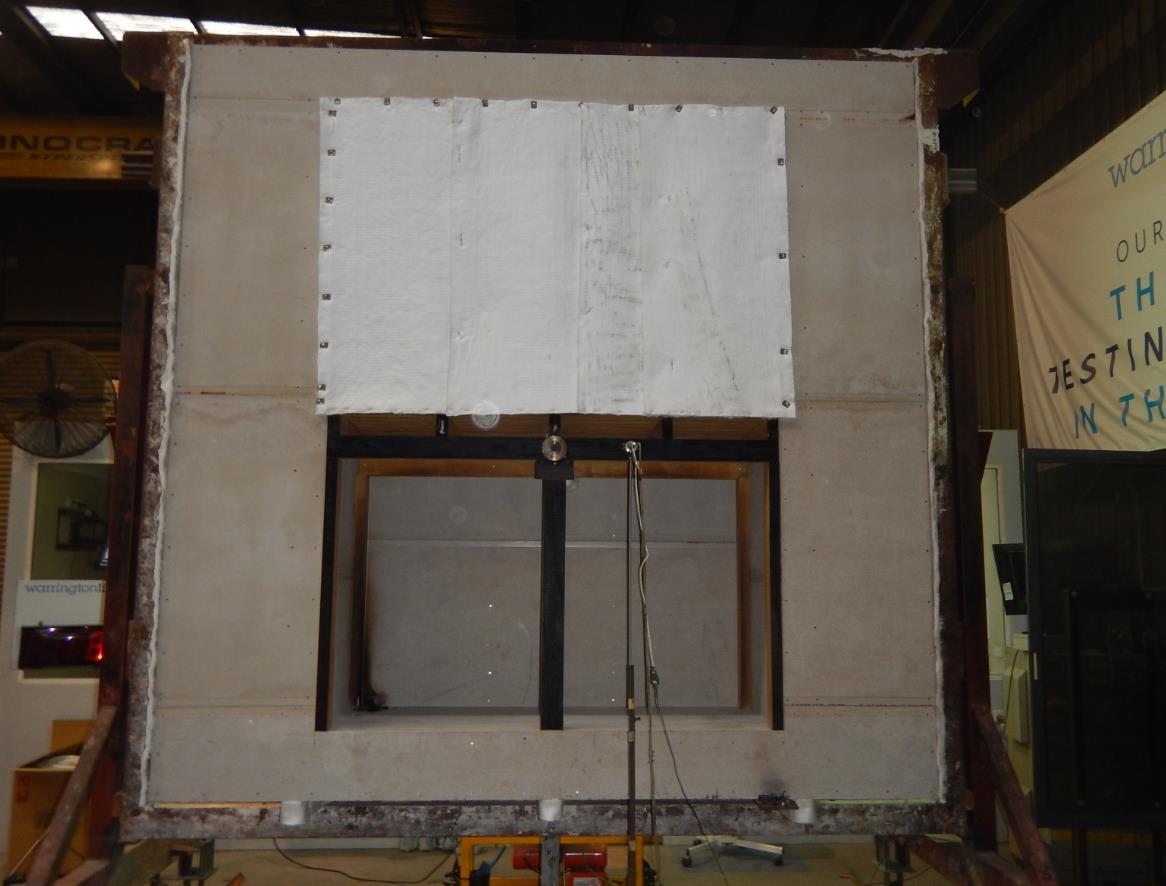
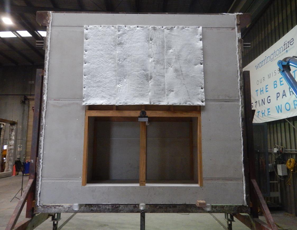
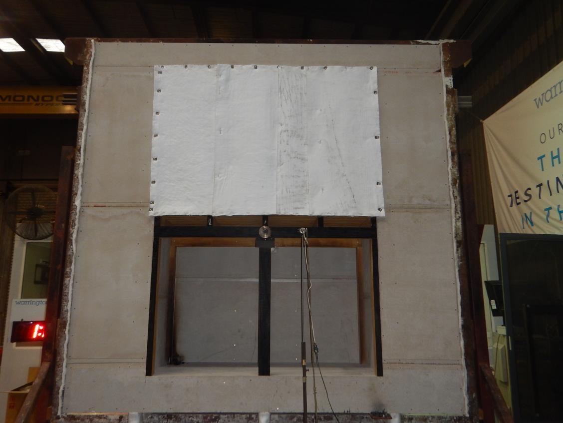
• The upper portion of the subfloor was baffled using a ceramic fibre blanket to shield the upper surface of the sub floor from radiant heat as per the requirements outlined in AS 1530.8.1:2018 under clause 22.2.2
3. Item name Framing
Product name 90 × 45 MGP10 Radiata pine
Density 489 kg/m3 (measured)
Location Located around the perimeter of the specimen and the wall system. Noggings were located at nominal 1000 mm centres to the sides of the specimen. Jack studs were located at nominal 300 mm centres above and below the specimen.
Fixings Assembled using 3.06 × 75 mm long bright smooth shank framing nails.
4. Item name Unexposed cladding
Product name 10 mm thick standard plasterboard
Density 566 kg/m3 (measured)
Location Fixed directly to the timber framing on the unexposed face of the specimen.
Fixings 6g × 32 mm bugle head plasterboard screws at approximately 300 mm centres through the timber framing.
5. Item name Exposed cladding
Product name 9 mm thick CSR Cemintel® fibre cement board
Density 1625 kg/m3 (nominal)
Location Fixed directly to the timber framing on the exposed face of the specimen.
fixings 6g × 32 mm bugle head plasterboard screws at approximately 200 mm centres through the timber framing.
6. Item name Eaves sheet lining
Product name 6 mm thick CSR Cemintel® fibre cement board
Density 1625 kg/m3 (nominal)
Location Fixed directly to the timber framing along the eaves on the exposed side.
fixings 6g × 32 mm bugle head plasterboard screws at approximately 200 mm centres through the timber framing.
7. Item name Ground floor lining
Product name 13 mm thick GYPROCK® Fyrchek™ plasterboard
Density 833 kg/m3 (nominal)
Location Fixed directly to the timber framing below the subfloor stumps
Fixing 6g × 32 mm bugle head plasterboard screws at approximately 200 mm centres through the timber framing.
8. Item name Ground floor lining
Product name 6 mm thick CSR Cemintel® fibre cement board
Density 1625 kg/m3 (nominal)
Test standard: Clauses 14 and 22 of AS 1530.8.1:2018
Job number: FRT20042
Revision: R1.0
Test sponsor: Wood Modification Technologies Limited Page 7 of 23
Item Description
Wall system
Location Above the plasterboard (item 7) and fixed through to the timber framing at the base of the wall
Fixing
Overall size
Installation
6g × 32 mm bugle head plasterboard screws at approximately 200 mm centres through to the timber framing.
3000 mm wide × 3000 mm high × 109 mm thick
• Two 90 × 45 timber stud frames (item 3) with the central frame offset 750 mm back.
• The timber framing was assembled using 3.06 × 75 mm long bright smooth shank framing nails.
• The exposed side of the timber framing (item 3) was clad using 9 mm thick fibre cement board (item 5).
• A 250 mm high eave detail lined with 6 mm thick fibre cement (item 6) and a 250 mm high non-combustible ground floor detail were also incorporated into the specimen using the ground floor linings (items 7 and 8).
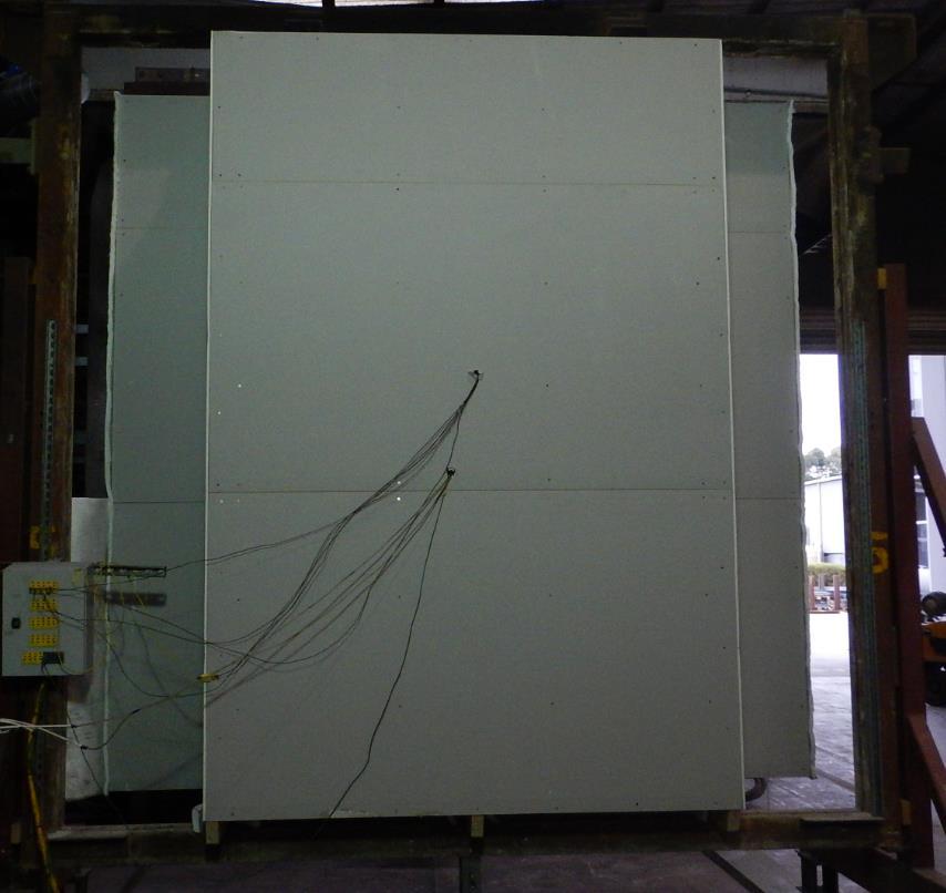
• The unexposed side of the timber framing was lined with 10 mm thick regular plasterboard (item 4).
Table 6 lists the installation details for the test specimen.
Table 6 Installation details
Item Detail
Start date for construction of separating element 03 May 2021
Sub-floor constructed on 04 May 2021
Separating element constructed by Representatives of Warringtonfire Melbourne.
Sub-floor constructed by Representatives of Warringtonfire Melbourne.
Sub-floor installed into the separating element by Representatives of Warringtonfire Melbourne. Symmetry Asymmetrical due to:
• The upper face of the deck was shielded from the radiant heat source.
• The exposed side of the wall being clad with 9 mm thick fibre cement and the unexposed side lined with 10 mm thick regular plasterboard. It was confirmed that the system was exposed to heat from the side that would normally face the outside of the building.
Table 7 details the test procedure for this simulated bushfire test
Table 7 Test procedure
Variations
Pre-test conditioning
The construction and installation of the test specimen was completed on 7 May 2021. The test specimen was subjected to normal laboratory
Test standard: Clauses 14 and 22 of AS 1530.8.1:2018
Job number: FRT20042
Revision: R1.0
Test sponsor: Wood Modification Technologies Limited Page 8 of 23
Item Detail
Sampling / specimen selection
Ambient laboratory temperature
Test duration
Instrumentation and equipment
temperatures and conditions between the completion of construction of the test specimen and the start of the test.
The laboratory was not involved in sampling or selecting the test specimen for the simulated bushfire test
The results obtained during the test only apply to the test samples as received and tested by Warringtonfire.
Start of the test 22 °C
Minimum temperature 22 °C
Maximum temperature 38 °C
The test was stopped after 60 minutes in accordance with the procedures in AS 1530.8.1:2018.
The instrumentation was provided in accordance with AS 1530.8.1:2018 as follows:
• The unexposed side specimen temperatures were measured by Type K thermocouples with wire diameters less than 0.5 mm soldered to 12 mm diameter × 0.2 mm thick copper discs covered by 30 mm × 30 mm × 2.0 mm thick inorganic insulating pads.
• The thermocouple positions are shown in Table 10 and in Figure 5 in Appendix D
• A Ø3 mm gap gauge was available during the test to assess the performance of the specimen under the criteria of integrity.
• A pilot ignition source was available to assess any areas of the specimen producing significant quantities of volatiles.
• The crib was conditioned for at least 24 hours in a conditioning oven and removed 1 hour before the start of the test.
• The crib was weighed to confirm that it was within the 0.152 ± 0.03 kg mass required by the standard. The crib was lit over a 2 minute period – 20 seconds on the upper 0.10 m × 0.10 m face. 20 seconds on each of the 0.54 m × 0.10 m faces, and a further 20 seconds on the upper 0.10 m × 0.10 m face – using an oxyacetylene torch with Type 551 size 8 × 10 heating tip.
• Radiant heat flux measurements – to determine the irradiance received and transmitted from the exposed face of the specimen – were taken using Medtherm heat flux gauges.
• The irradiance received at the front of the subfloor system was measured by a heat flux meter for the radiant exposure portion of this test
• During the test a second heat flux gauge were centrally located next to the subfloor at a distance of 250 mm from the exposed side of the specimen during the 20 to 60 minutes periods of the test.
• The heat flux gauge positions are shown in Figure 4 in Appendix E
Table 8 summarises the results the specimen achieved against the performance criteria listed in clauses 14 and 22 of AS 1530.8.1:2018.
Appendix E includes details of the measurements taken during the test.
Table 9 in Appendix B includes observations of any significant behaviour of the specimen and details of the occurrence of the various performance criteria specified in AS 1530.8.1:2018
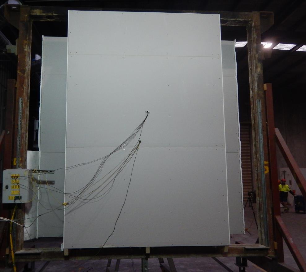
Photographs of the specimen are included in Appendix F
Test standard: Clauses 14 and 22 of AS 1530.8.1:2018
Job number: FRT20042
Revision: R1.0
Test sponsor: Wood Modification Technologies Limited Page 9 of 23
Table 8 Test results
Formation
greater than 3 mm
Sustained flaming for 10 s on the non-fire side
failureFlaming on the fire-exposed side at the end of the 60 minute test period No failure -
Radiant heat flux 365 mm from the non-fire side exceeding 15 kW/m2
Mean and maximum temperature rises greater than 140 K and 180 K
Radiant heat flux 250 mm from the specimen, greater than 3 kW/m2 between 20 min and 60 min
Not applicable -
No failure -
No failure -
Not applicable -
result BAL AA40
5. Application of test results
These results only relate to the behaviour of the specimen of the element of construction under the particular conditions of the test. They are not intended to be the sole criteria for assessing the potential fire performance of the element in use, and they do not necessarily reflect the actual behaviour in fires.
5.2 Variations from the tested specimen
It is recommended that any proposed variation to the tested configuration – other than as permitted under the field of direct application specified in Appendix C – should be referred to the test sponsor. They should then obtain appropriate documentary evidence of compliance from Warringtonfire or another accredited testing authority.
5.3 Uncertainty of measurements
Test standard: Clauses 14 and 22 of AS 1530.8.1:2018
Job number: FRT20042
Test sponsor: Wood Modification Technologies Limited
Revision: R1.0
The leaders in the drawings represent the items listed in section 2.1 All measurements – unless indicated – are in millimetres.
Test standard: Clauses 14 and 22 of AS 1530.8.1:2018
Job number: FRT20042
Test sponsor: Wood Modification Technologies Limited
Revision: R1.0
Test standard: Clauses 14 and 22 of AS 1530.8.1:2018
Job number: FRT20042
Test sponsor: Wood Modification Technologies Limited
Revision: R1.0
Test standard: Clauses 14 and 22 of AS 1530.8.1:2018
Job number: FRT20042
Test sponsor: Wood Modification Technologies Limited
Revision: R1.0
Time Observation
Min Sec
00 00
00 03
The simulated bushfire radiant heat test started. Two flaming cribs (class AA) were placed against the test specimen. The initial temperature of the test specimen was approximately 22 °C.
The screen shielding the specimen from the radiant heat panel was removed and the test specimen was exposed to the radiant heat profile for BAL 40, as specified in AS 1530.8.1:2018.
01 41 Smoke was emitting from the specimen
02 00 The elements of the subfloor which were facing towards the radiant heat source had discoloured.
05 00 The stumps had charred slightly.
10 00
60 00
The screen was re-positioned in front of the furnace and exposure to the radiant heat profile of BAL 40 was stopped.
Monitoring of the test specimen against the performance criteria outlined in AS 1530.8.1:2018 continued.
There were no further changes to the specimen.
The test was stopped in accordance with the procedures outlined in AS 1530.8.1:2018.
Test standard: Clauses 14 and 22 of AS 1530.8.1:2018
Job number: FRT20042
Revision: R1.0
Test sponsor: Wood Modification Technologies Limited Page 14 of 23
Table 9 shows the observations of any significant behaviour of the specimen during the test. Table 9 Test observations
Note: The text, figures and tables in this appendix have been taken from AS 1530.8.1:2018.
The results of the fire test contained in the test report are directly applicable, without reference to the testing authority for a technical opinion, to similar constructions where one or more of the following changes have been made provided no individual component is removed or reduced:
• Increase in thickness of solid flooring material.
• Increase in cross-section of bearers and joists.
• Increase in the size of the deck.
• Variations to the height of the assembly above ground level.
Test standard: Clauses 14 and 22 of AS 1530.8.1:2018
Job number: FRT20042
Test sponsor: Wood Modification Technologies Limited
Revision: R1.0
15 of 23
Note:


• Red dots show unexposed thermocouple locations.
Test standard: Clauses 14 and 22 of AS 1530.8.1:2018
Job number: FRT20042
Test sponsor: Wood Modification Technologies Limited
Revision: R1.0
Note:

• Southern crib located at the base of the wall below the south front stump
• Northern crib located below the subfloor adjacent to the south rear stump
• Black dots show heat flux gauge locations.
• Orange dots show crib locations
Figure 5 Instrumentation locations (exposed side shown)
The instrumentation was positioned in accordance with the requirements of clause 22 of AS 1530.8.1:2018 – as summarised in Table 10 and Table 11
Test standard: Clauses 14 and 22 of AS 1530.8.1:2018
Job number: FRT20042
Test sponsor: Wood Modification Technologies Limited
Revision: R1.0
Test standard: Clauses 14 and 22 of AS 1530.8.1:2018
Job number: FRT20042
Test sponsor: Wood Modification Technologies Limited
Revision: R1.0
Less than 0.03 kW/m2 heat flux radiation was received by the heat flux gauge positioned centrally to the front of the specimen and 250 mm from the subfloor during the time period of 20 to 60 minutes of the test period.
Note: 1 Refer to Table 10 for locations of thermocouples as only a generic description is included in the table.
2 Limit time is the time to the nearest whole minute, rounded down to the nearest minute, at which the temperature recorded by any surface thermocouple does
Test standard: Clauses 14 and 22 of AS 1530.8.1:2018
Job number: FRT20042
Test sponsor: Wood Modification Technologies Limited
Revision: R1.0
Page 19 of 23
Figure 8 Unexposed surface of the deck – temperature vs time
not rise by more than 180K above the initial temperature, or the average of the external quarter point thermocouple measured temperatures does not rise by more than 140 K above the initial temperature.
‘_’ Under Limit column indicates the temperature limit was not exceeded during the test period or up until the time of integrity failure if a failure occurred.
Test standard: Clauses 14 and 22 of AS 1530.8.1:2018
Job number: FRT20042
Revision: R1.0
Test sponsor: Wood Modification Technologies Limited Page 20 of 23

Test standard: Clauses 14 and 22 of AS 1530.8.1:2018
Job number: FRT20042
Test sponsor: Wood Modification Technologies Limited
Revision: R1.0


Test standard: Clauses 14 and 22 of AS 1530.8.1:2018
Job number: FRT20042
Test sponsor: Wood
Revision: R1.0

Warringtonfire Australia Pty Ltd
ABN 81 050 241 524
Perth
Unit 22, 22 Railway Road
Subiaco WA 6008
Australia
T: +61 8 9382 3844
Sydney
Suite 802, Level 8, 383 Kent Street
Sydney NSW 2000
Australia
T: +61 2 9211 4333
General conditions of use
Canberra
Unit 10, 71 Leichhardt Street
Kingston ACT 2604
Australia
T: +61 2 6260 8488
Brisbane
Suite 6, Level 12, 133 Mary Street
Brisbane QLD 4000
Australia
T: +61 7 3238 1700
Melbourne – NATA accredited laboratory
409-411 Hammond Road
Dandenong South VIC 3175
Australia
T: +61 3 9767 1000
The data, methodologies, calculations and results documented in this report specifically relate to the tested specimen/s and must not be used for any other purpose. This report may only be reproduced in full. Extracts or abridgements must not be published without permission from Warringtonfire.
Test standard: Clauses 14 and 22 of AS 1530.8.1:2018
Job number: FRT20042
All work and services carried out by Warringtonfire are subject to, and conducted in accordance with, our standard terms and conditions. These are available on request or at https://www.element.com/terms/terms-and-conditions
Revision: R1.0
Test sponsor: Wood Modification Technologies Limited Page 23 of 23
Heading