Compressed Air Filters
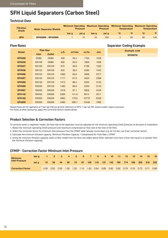
SFH Liquid Separators (Carbon Steel) Technical Data Filtration Grade
Water Separator Models
SFH
SFH029N - SFH209N
Minimum Operating Maximum Operating Pressure Pressure bar g
psi g
bar g
psi g
ºC
ºF
ºC
ºF
1
15
16
232
2
35
60
140
Flow Rates Model
Minimum Operating Maximum Operating Temperature Temperature
Separator Coding Example Pipe Size
L/S
m³/min
m³/hr
cfm
DN80
490
29.4
1764
1038
DN100
DN80
500
30.0
1800
1059
SFH037
DN100
DN100
610
36.6
2196
1293
SFH038
DN125
DN100
633
38.0
2280
1342
SFH066
DN125
DN125
1093
65.6
3936
2317
SFH067
DN150
DN125
1117
67.0
4020
2366
SFH088
DN150
DN150
1473
88.4
5304
3122
SFH089
DN200
DN150
1483
89.0
5340
3143
SFH097
DN200
DN200
1618
97.1
5826
3429
SFH142
DN250
DN200
2365
141.9
8514
5011
SFH180
DN300
DN200
2992
179.5
10770
6339
SFH209
DN350
DN200
3485
209.1
12546
7385
Inlet
Outlet
SFH029
DN80
SFH030
Example code SFH067N
Stated flows are for operation at 7 bar (g) (102 psi g) with reference to 20°C, 1 bar (a), 0% relative water vapour pressure. For flows at other pressures, apply the correction factors shown below.
Product Selection & Correction Factors To correctly select a separator model, the flow rate of the separator must be adjusted for the minimum operating (inlet) pressure at the point of installation. 1. Obtain the minimum operating (inlet) pressure and maximum compressed air flow rate at the inlet of the filter. 2. Select the correction factor for minimum inlet pressure from the CFMIP table (always round down e.g. for 5.3 bar, use 5 bar correction factor) 3. Calculate the minimum filtration capacity. Minimum Filtration Capacity = Compressed Air Flow Rate x CFMIP 4. Using the minimum filtration capacity, select a filter model from the flow rate tables above (filter selected must have a flow rate equal to or greater than the minimum filtration capacity).
CFMIP - Correction Factor Minimum Inlet Pressure Minimum Inlet Pressure Correction Factor
12
bar g
1
2
3
4
5
6
7
8
9
10
11
12
13
14
15
16
psi g
15
29
44
58
73
87
100
116
131
145
160
174
189
203
218
232
4.00
2.63
2.00
1.59
1.33
1.14
1.00
0.94
0.89
0.85
0.82
0.79
0.76
0.73
0.71
0.68


