
Surface Modeling of Spur Gear Using Surface Model in SolidWorks

Page 1


International Research Journal of Engineering and Technology (IRJET) e-ISSN:2395-0056

Volume: 12 Issue: 09 | Sep 2025 www.irjet.net p-ISSN:2395-0072

Surface Modeling of Spur Gear Using Surface Model in SolidWorks

Hanoi University of Science and Technology, 1 Dai Co Viet, Hai Ba Trung, Hanoi, Vietnam.

Abstract

Sofar,inteachingthetheoryandpracticeoftechnicalgraphicexercises,solidmodelsaremainlyused.Meanwhile,thedesign andmanufacturingofindustrialproductsarebecomingincreasinglysophisticated,requiringmorecomplexgeometricmodels. Applying the Surface model in the design of spur gears makes the teaching and practice of mechanical design subjects in engineeringschoolsmoreintuitive.Theapplicationofspurgearmoduleconstructionalsohelpsstudentsinsimulationdesign inmachinedesign,therebygraduallytraininghigh-qualityhumanresourcesinmechanicalengineering.

Keywords:Spurgear;SolidWorks;VisualBasic.

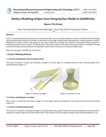
1. Surface Modeling Methods

1.1. Surface modeling by extrusion (generatrix)

This type of surface is created by extruding a straight or curved edge in a specified direction. The command group used:

ExtrudeSurface(Figure1).

1.2. Surface modeling by revolution

This surface is created by revolving a straight or curved edge around a specified axis. The command used: Revolved Surface (Figure2).

1.3. Surface modeling along a path

Thesurfaceiscreatedbysweepingastraightorcurvedprofilealongapath.Profilescanbeparallel(KeepNormalConstant) or maintainaconstantangletothepath(FollowPath).ThissurfaceiscreatedusingtheSweptSurfacecommand(Figures3–5).

Figure1:Extrudeastraight
Figure2:Extrudescurved

International Research Journal of Engineering and Technology (IRJET) e-ISSN:2395-0056

Volume: 12 Issue: 09 | Sep 2025 www.irjet.net p-ISSN:2395-0072

Figures3:Sweepastraight Figures4:Sweepacurved Figures5:Sweepacurved

1.4. Surface modeling with freeform profiles

Thisisthemostdiversetypeofsurfacemodeling.Freeformgeometricprofilesaredesignedtobestmeethumanfunctionaland aestheticrequirements.Manymodernindustrialproductsusethin-shellstructureswithdiverseandaestheticsurfacedesigns. Twoapproachesarecommonlyused:

1.4.1.Creatingsurfacesbyconnectingmultipleclosedoropen2Dprofiles(withorwithoutguidecurves),usingLoftedSurface, BoundarySurface(Figures4,5).

1.4.2.Creatingsurfacesbycombiningclosed2Dprofiles,usingFillSurface,PlanarSurface,RuledSurface(Figures6,7).

Figures6:Createsurfacebycombining closed2Dprofiles-fillsurface

2.1. Fundamentals of programming

Figures7:Createsurfacebycombining closed2Dprofiles-Ruledsurface

VBA (Visual Basic for Applications) is a rapidly developing technology integrated into host applications, based on the COM (ComponentObjectModel)architecture.AdvantagesofVBAinclude:

-Anintegrateddevelopmentenvironment(IDE)builtintothehostapplication.

-UsestheVBlanguage,simpleandwidelyused.

-Basedonthehostapplication'sobjectmodel,makingdevelopmentintuitive.

-Accesstonearlyallbuilt-infeaturesofthehostapplication.

-Fasterexecutionspeedcomparedtoexternalprograms.

-VBAprogramscanbeembeddedinhostfiles(e.g.,CADdrawings)orsavedasindependentprojects.

SolidWorkssupportsVBAwithextensivedocumentation,enablingquickandeasyapplicationdevelopment.

2. Using Visual Basic Programming in SolidWorks for Spur Gear Surface Modeling

International Research Journal of Engineering and Technology (IRJET) e-ISSN:2395-0056

Volume: 12 Issue: 09 | Sep 2025 www.irjet.net p-ISSN:2395-0072

2.1.2. Summary of Visual Basic program for standard spur gear modeling

In this study, parametric design was implemented in SolidWorks. Geometric features of spur gears were analyzed, and parametric variables defined, with each control point determined in the Cartesian coordinate system. During development, API functions such as CreateLine, FeatureRevolve, FeatureCut, CreatePlaneAtAngle3, InsertCutBlend, and FeatureCircularPattern were used. Parameterized spur gear design provides a basis for FEM stress analysis and assembly simulation.

Spur gears are among the most fundamental mechanical devices, widely used in automotive gearboxes, engineering machinery,andmotiontransmissionbetweenparallelshafts.Straight-toothspurgearsarethemosteconomicalduetoeaseof manufacturing. Accurate 3D models are essential for FEM analysis, motion/dynamic simulation, and CNC manufacturing. Developingaparametricmodelingmoduleforspurgearsin3DCADimprovesdesignefficiencyandquality.

2.2. Geometrical Shape of Spur Gear

Thegeometryofthespurgear[3]isshowninFigure10.Theyhavestraightandslenderteeth.Theflankcurvesoftheteethare involutecurves.Thesearegeneratedwhenapointrollswithoutslippingalongthebasecircle.

Thecross-sectionofthegeartoothisconstructedbydetermininganchorpointswithseparatex,ycoordinates,thenconnecting themusingthe Spline function(Figure10).

2.3. Results of Spur Gear Design

The design variables are defined according to the geometry of the spur gear described above, and the design equations are parameterized in terms of the gear module (m), number of teeth (z), and face width coefficient (b), which are treated as parametric design variables. Other parameters are derived from the input variables using the Equation module. The result obtainedafterrunningtheprogramisshowninFigure11.

The parametric design process, based on the above study, was achieved using SolidWorks 2020 API functions [1][4][5]. The workflowdiagramofthisprocessisshowninFigure12.

Figure10:Creadsurfaceofgeartool
Figure11:Spurgeardesign

International Research Journal of Engineering and Technology (IRJET) e-ISSN:2395-0056

Volume: 12 Issue: 09 | Sep 2025 www.irjet.net p-ISSN:2395-0072

Figure12.Workflowofparametricdesign

Step 1: Creategearblankusingthe Extrude functioninSolidWorks.

Step 2: Generate two involute curves for the tooth space configuration using splines on the reference plane, bounded by tip androotcircles.Thesecurvesaredesignedfromtheinputvariablesmodule(m)andnumberofteeth(z)usingthe Equation function.

Step 3: Createthetoothprofileusingthetwoinvolutecurvesandthetipandrootcircles.

Step 4: Generatethetoothgeometryonthegearblankusingthe Extrude function.

Step 5: Createacircularpatternofthetoothprofilearoundthegearblank.

Step 6: Addstandardholesandslots.

2.4.

Programming Results

By running macros written in Visual Basic code and SolidWorks API functions, a standard spur gear model can be automatically and quickly generated after interaction. A pair of spur gears is created by running the assembled macros, showingthattheyarewell-matched,intuitive,andprecise(seeFigure13).

International Research Journal of Engineering and Technology (IRJET) e-ISSN:2395-0056

This program can generate a standard gear library, replacing the default software library, and correcting errors in tooth surfacegenerationinconsistentwithstandardprofiles.

It also supports students in developing machine design projects more intuitively and accurately, as well as simulating the operationofassemblies.

3. Results

Bydefiningdesignvariablessuchasmodule(m),numberofteeth(z),andfacewidthcoefficient(b),thespurgeargeometry is parametricallydescribed.Otherdimensionsarederivedusingequations.Theparametricdesignworkflow(Figure12)consists of:

1.CreategearblankusingExtrude.

2.Generateinvolutecurves(usingsplines)definedbymoduleandtoothnumber.

3.Constructtoothprofilefrominvolutecurvesandaddrootandtipcircles.

4.Extrudetoothprofileontotheblank.

5.Createcircularpatternofteetharoundtheblank.

6.Addstandardholesandslots.

RunningtheVisualBasicmacrosandSolidWorksAPIfunctionsgeneratesastandardspurgearautomatically.Assembledgear pairs(Figure13)showaccurate,intuitive,andpreciseresults.

The developed program can create a gear library following standards, replacing built-in CAD libraries, correcting profile errors,andsupportingstudentdesignprojectswithaccuratesimulationcapabilities.

4. Conclusion

Thisstudyanalyzedthestructuralfeaturesofspurgears,definedparametricdesignvariables,andimplementedaninteractive design interface. Using Visual Basic and SolidWorks API, a parametric spur gear model was successfully developed. Results showedaccurateand efficientmodeling,enablingintegrationwithFEManalysis,motionsimulation,andCNCmanufacturing.

Volume: 12 Issue: 09 | Sep 2025 www.irjet.net p-ISSN:2395-0072 © 2025, IRJET | Impact Factor value: 8.315 | ISO 9001:2008 Certified Journal | Page422

Figure13:Apairofspurgears

International Research Journal of Engineering and Technology (IRJET) e-ISSN:2395-0056

Volume: 12 Issue: 09 | Sep 2025 www.irjet.net p-ISSN:2395-0072

Although this paper focuses on spur gears, the method also provides a reference for helical and herringbone gears, to be studiedinfuturework.

References

[1] Nguyen Hong Thai, Application of SolidWorks in Mechanical Design, Science and Technology Publishing House.

[2]LeTanHung,HuynhQuyetThang(2002).EngineeringGraphics.ScienceandTechnologyPublishingHouse,Hanoi.

[3]NguyenTrongHiep,NguyenXuanLam(1998).FundamentalsofMachineDesign.EducationPublishingHouse(reprint).

[4]Fahiem,M.A.,Haq,S.A.,Saleemi,F.(2007).AReviewof3DReconstructionTechniquesfrom2DOrthographicLineDrawing. GeometricModellingandImaging(GMAI07),July,pp.60–66.

[5]Aldefeld(1983).OnAutomaticRecognitionof3DStructuresfrom2DRepresentation.ComputerAidedDesign,Vol.15,No.2, pp.59–64.

[6] K. Preiss (1984). Constructing the Solid Representation from Engineering Projection. Computer & Graphics, Vol.8, No.4, pp.381–389.

© 2025, IRJET | Impact Factor value: 8.315 | ISO 9001:2008 Certified Journal | Page423

Turn static files into dynamic content formats.

Create a flipbook