
International Research Journal of Engineering and Technology (IRJET) e-ISSN: 2395-0056
Volume: 12 Issue: 05 | May 2025 www.irjet.net p-ISSN: 2395-0072


International Research Journal of Engineering and Technology (IRJET) e-ISSN: 2395-0056
Volume: 12 Issue: 05 | May 2025 www.irjet.net p-ISSN: 2395-0072
HEMAVATHI G1, Dr. L. GOVINDARAJU2
1PG Student, Department Of Civil Engineering, UVCE, Jnanabahrathi Campus, Bengaluru, Karnataka, India
2Professor, Department Of Civil Engineering, UVCE, Jnanabahrathi Campus, Bengaluru, Karnataka, India
Abstract - Multistoriedbuildingsarecomplexstructuresthat require careful consideration of various factors, including seismic activity, to ensure their stability and safety. These buildings, which can be used for residential, commercial, or industrial purposes, are particularly vulnerable to seismic forces due to their height and weight. This study investigates the seismic behavior of multistoried buildings (G+10 and G+20) with and without floating columns, situated in seismic zones IV and V with soft soil conditions. Various seismic analyses, including equivalent static analysis, response spectrum analysis, modal analysis, time history analysis, and pushover analysis, were performed usingETABSandSAP2000 software. The results show that structures with floating columns exhibit maximum storey displacement and drift, although both structures satisfy code recommendations. The provision of steel inverted V bracings significantly improves the seismic performance, bringing both structures within the life safety state. Soil-structure interaction analysis further highlights the importance of considering the interaction between the structure and the soil, with surface springs and steel bracings ensuring the structure's stability. This study concludes that multistoried buildings with and without floating columns can be made safe with the provision of steel invertedV bracings, andemphasizes theimportanceofcareful seismic design and analysis for these complex structures.
Key Words: Multistoried Buildings, Floating Column, Seismic Zones, Steel Inverted V Bracings, Equivalent Static Analysis, Response Spectrum Analysis, Pushover Analysis, Soil-Structure Interaction, Structural Stability.
Multistoriedbuildingsarecomplexstructuresthatconsistof multiplelevelsorfloors,designedtoaccommodatevarious activitiessuchasresidential,commercial,orindustrialuses. These buildings are a crucial part of modern urban landscapes, providing space for living, working, and other activities.Theconceptofmultistoriedbuildingshasevolved significantly over time, driven by advances in materials, engineering, and architectural design. The design of multistoried buildings requires careful consideration of structuralintegrity,safety,andfunctionality,includingthe choiceofstructuralsystem,load-bearingcapacity,andsafety features. Multistoried buildings offer several benefits, including space optimization, increased density, and economic benefits. However, they also present challenges
such as design and construction complexity, safety and security concerns, and sustainability and environmental impact.Byunderstandingthecharacteristicsandchallenges ofmultistoriedbuildings,architects,engineers,andbuilders cancreatestructuresthatmeettheneedsofoccupantswhile ensuringsafety,sustainability,andfunctionality.
Theterm"floatingcolumn"referstoaverticalelementthat restsonabeam,whichisahorizontalmember,atitslower level. A column is intended to be a vertical member that begins at foundation level and transfers the load to the ground. When a column from the top of the building is stopped at a lower level, typically at the ground story, it createsacommontypeofdiscontinuityintheloadpathin moment frames. In these situations, loads from the overhanging sections divert and reach the closest column thatremainscontinuousallthewaytothefoundation.This increasesthestrainonthegroundfloorcolumnsandmay resultintheirfailure
Abracedframeisastructuralsystemfrequentlyemployedin buildings that experience lateral forces, such as wind and seismicactivity.Typicallyconstructedfromstructuralsteel, the members of a braced frame are capable of efficiently handling both tension and compression. This type of constructioniswidelyutilizedduetoitscost-effectiveness and straight forward analysis. The economic advantage is derived from the pinned connections between beams and columns.Bracing,whichenhancesstabilityandcounteracts lateral forces, can consist of diagonal steel members or a concretecore.Inbracedstructures,beamsandcolumnsare designedsolelyforverticalloads,withthebracingsystem responsibleformanagingalllateralforces.Thebeamsand columnssupportvertical loads,whilethebracingsystems addresslateralloads.Inthecurrentstudy,duringpushover analysis,thestructureissubjectedtopotentialcollapse.To mitigatethisrisk,invertedVbracingsareimplemented.

International Research Journal of Engineering and Technology (IRJET) e-ISSN: 2395-0056
Volume: 12 Issue: 05 | May 2025 www.irjet.net p-ISSN: 2395-0072
2.1 Objectives of the Study
Theprimaryobjectiveofthisstudyistoevaluatetheseismic performance of multi-storied buildings with floating columns.
Toassesstheeffectsoffloatingcolumnparameters onseismicresponse.
Tocompareseismicperformancewithandwithout floatingcolumns.
To perform and compare linear dynamic Modal analysismethodtodeterminenaturalfrequencies andmodeshapesofthestructurewithandwithout floatingcolumn.
ToperformandcomparenonlineardynamicTime Historyanalysismethodtoevaluatetheresponseof structure with and without floating column to dynamicloads.
ToperformandcomparenonlinearstaticPushover analysis method to evaluate the behavior of structurewithandwithoutfloatingcolumnunder staticloads.
To investigate the impact of soil-structure interaction on seismic response of structure with and withoutfloatingcolumn.
2.2 Methodology
Thisstudyemploysacomprehensiveapproachtoevaluate theseismicperformanceofG+10andG+20storeybuilding with and without floating column using ETABS 21 and SAP200023software.
ANALYSIS METHODS:
1. Equivalentstaticanalysis(ESA)
2. Responsespectrumanalysis(RSA)
3. Lineardynamicmodalanalysis
4. Nonlineardynamictimehistory
5. NonlinearStaticPushoverAnalysis(NSPA)
6. Soil-StructureInteraction(SSI)
3. MODELS CONSIDERED FOR ANALYSIS
The model consists of a Ten storey and twenty storey Reinforcedconcrete(RC)framestructurelocatedinseismic zone IV & zone V. Characterized by high seismicity, and situatedonsoftsoilcondition
InPresentstudy,fourmodelsareconsideredforanalysisas follows:
MODEL1- Inmodel1,I-shapeG+10buildingwithoutfloating columnisconsideredandanalyzedforsoftsoilinzoneIV& zoneV
MODEL 2-Inmodel2,I-shapeG+10buildingwithfloating columnat4th&7thstoreyisconsideredandanalyzedforsoft soilinzoneIV&zoneV
MODEL 3- In model 3, I-shape G+20 building without floatingcolumnisconsideredandanalyzedforsoftsoil in zoneIV&zoneV.
MODEL 4-Inmodel4,I-shapeG+20buildingwithfloating columnat7th,14th&17thstoreyisconsideredandanalyzed forsoftsoilinzoneIV&zoneV
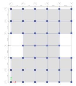
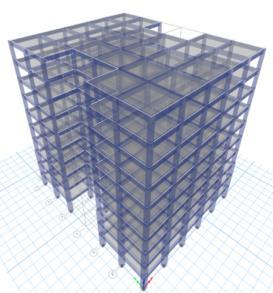
-1:MODEL1planand3Dview
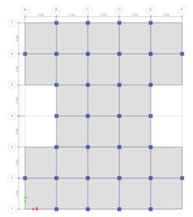
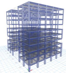
FIG -2:MODEL2planand3Dview

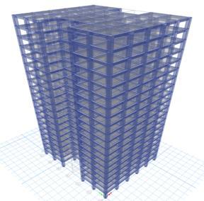
FIG -3:MODEL3planand3Dview

International Research Journal of Engineering and Technology (IRJET) e-ISSN: 2395-0056
Volume: 12 Issue: 05 | May 2025 www.irjet.net p-ISSN: 2395-0072


FIG -4:MODEL4planand3Dview
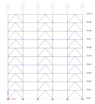
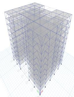
FIG -5:Elevationand3Dviewofstructurewithbracings
3.1 Geometry Of The Model Considered
Table -1: Geometryofthemodelconsidered
No. of storey’ s
No. of bays in X-direction 5 5
No. of bays in Y- direction 6 6
X-direction bay width 5m 5m
Y-direction bay width 5m 5m
Height of bottom storey 3m 3m
Height of storey 3m 3m
3.2 Section Properties
Table -2: SectionProperties
PARAMETERS BUILDING CONFIGURATION
Length in Xdirection 25
Length in Ydirection 30
No.ofstoreys Ten(G+10)&Twenty(G+20)
Beam B=350x600mm,M25gradeconcrete
Column C=700x700mm,M25gradeconcrete
Slab 150mmM25gradeconcrete
Bracing ISMB300x300
3.3 Loads considered
Table -3: Loadsconsidered
Load Type
3.4 Seismic Parameters
Table -4: seismicparameters
Structure type
Multi storied RC rigid jointed plane frame(SMRF)
Typeofsoil SOFT,TYPEIII
Zone IV&V
Dampinginstructure 5%
Importancefactor 1
ScaleFactor 1.962
Responsereductionfactor 5
4 RESULTS AND DISCUSSION
4.1 RESPONSE SPECTRUM ANALYSIS
4.1.1 STOREY DISPLACEMENT
ThemaximumstoreydisplacementofthestructureisinYdirection.HencetheresultsaretakeninY-directionforzone IV & zone V with soft soil condition. Storey displacement variationsareshowninchartbelow.Fromchart1&2itcan beconcludethatbothmodel1inzoneVandmodel2inzone V isshowingmaximum storey displacement andstructure withbracingsshowsminimumdisplacement.Fromchart3& 4itcanbeconcludethatbothmodel3inzoneVandmodel4 in zone V is showing maximum storey displacement and structurewithbracingsshowsminimumdisplacement.

International Research Journal of Engineering and Technology (IRJET) e-ISSN: 2395-0056
Volume: 12 Issue: 05 | May 2025 www.irjet.net p-ISSN: 2395-0072
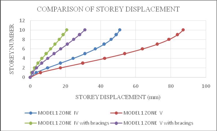
-1:Model1storeydisplacement
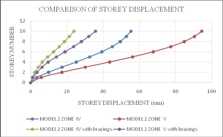
Chart -2:Model2storeydisplacement
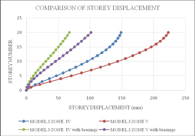
Chart -3:Model3storeydisplacement
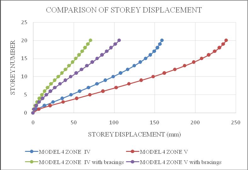
Chart -4:Model4storeydisplacement
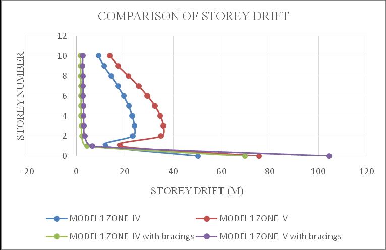
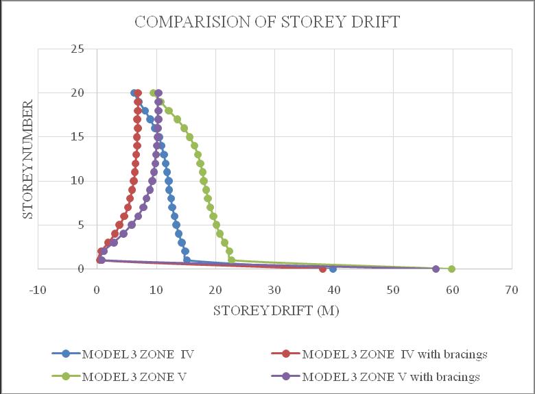
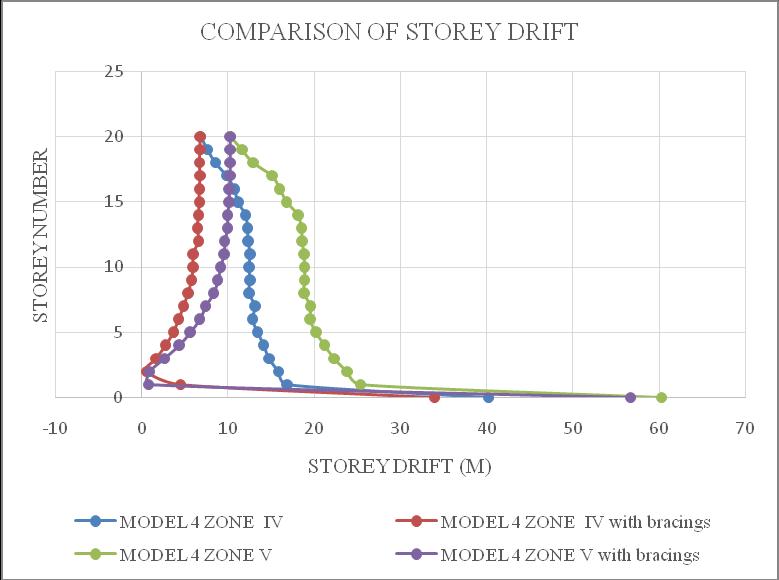
ThemaximumdriftofthestructureisinY-direction.Hence theresultsaretakeninY-directionforzoneIV&zoneVwith softsoilcondition.Storeydrift variationsareshowninchart below.Fromchart5&6itcanbeconcludethatbothmodel1 inzoneVandmodel2inzoneVisshowingmaximumstorey drift and structures with bracings shows minimum storey drift.Fromchart7&8itcanbeconcludethatbothmodel3in zoneVandmodel4inzoneVisshowingmaximumstorey drift and structures with bracings shows minimum storey drift.
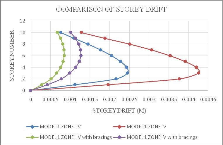
Chart -5:Model1storeydrift

International Research Journal of Engineering and Technology (IRJET) e-ISSN: 2395-0056
Volume: 12 Issue: 05 | May 2025 www.irjet.net p-ISSN: 2395-0072
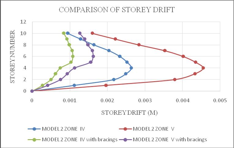
Chart 6:Model2storeydrift

Chart 7:Model3storeydrift
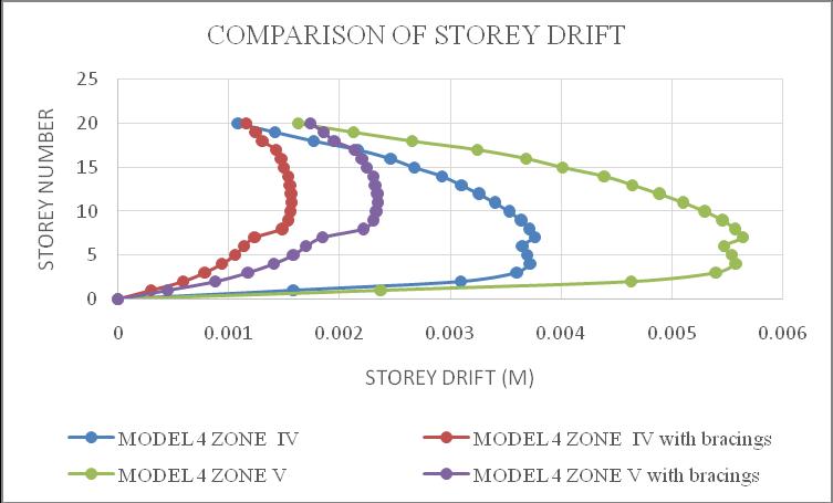
Chart 8:Model4storeydrift
4.2 TIME HISTORY ANALYSIS
Non-linear time history analysis is a dynamic analysis method used to evaluate the seismic performance of
structures under real earthquake ground motions. Bhuj Groundmotionisconsideredforanalysis.
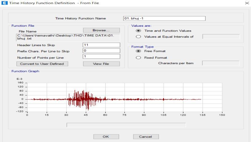
FIG -6:DefineGroundmotion
Themaximumstoreydisplacementoccursattopstoreyof thebuilding.
WhencomparedtoEquivalentstaticandresponsespectrum analysis, in non-linear time history analysis the storey displacementdecreasesandtheresultsobtainedarewithin thelimitsi.e.,H/250aspercoderecommendation.
The results are taken for model 1, model 2, model 3 and model4inzoneIV&Vwithsoftsoilcondition.
Formodel1zoneIVwithoutbracingsthemaximum storey drift occurs at Storey 4 with a value of 0.000978m.
Formodel1zoneVwithoutbracingsthemaximum storey drift occurs at Storey 3 with a value of 0.001458m.
Formodel 2zoneIVandzoneV without bracings themaximumstoreydriftoccursatStorey4witha valueof0.001128mand0.001692m.
Formodel1zoneIVandzoneVwithbracingsthe maximum storey drift occurs at Storey 7 with a valueof0.000591mand0.000887m.
Formodel 2zone IVandzoneV with bracingsthe maximum storey drift occurs at Storey 6 with a valueof0.000791mand0.001187m.
Formodel3zoneIVandzoneVwithoutbracingsthe maximum storey drift occurs at Storey 4 with a valueof0.001126mand0.001689m.

International Research Journal of Engineering and Technology (IRJET) e-ISSN: 2395-0056
Volume: 12 Issue: 05 | May 2025 www.irjet.net p-ISSN: 2395-0072
Formodel4zoneIVandzoneVwithoutbracingsthe maximum storey drift occurs at Storey 5 with a valueof0.001173mand0.001759m.
Formodel 3zone IVandzoneV with bracingsthe maximum storey drift occurs at Storey 15 with a valueof0.000805mand0.001278m.
Formodel 4zone IVandzoneV with bracingsthe maximum storey drift occurs at Storey 17 with a valueof0.001044mand0.001544m.
PushoveranalysisisdoneforG+10andG+20storeybuilding withandwithoutfloatinginzoneIVandZoneVwithsoftsoil condition.
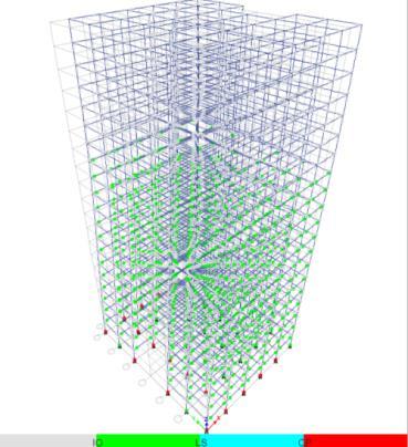
ResultsaretakenforModel1,Model2,Model3and Model4inZoneIV&ZoneVwithoutbracings,each model exhibits different displacement at performance point indicating varying structural capacities.
All models exceed the collapse prevention performancelevel,itmeansthatthestructurehas exceeded its capacity to withstand seismic forces and is at a high risk of collapse, and significant damageisexpected.Thestructuremayexperience catastrophicfailure,resultinginsignificantdamage, injury or loss of life. Therefore retrofitting is necessary to enhance the structure’s seismic capacityandreducetheriskofcollapse.
AsaretrofittingmeasuressteelinvertedVbracings are provided alternatively at outer side of the structure.
Afterprovidingbracings,allmodelsarewithinlife safety (LS) performance level. It ensures that the structurescanwithstandseismicforceswithsome damage but without compromising life safety. By achievingalifesafetystate,structurescanminimize the risk of injury or loss of life during seismic events.

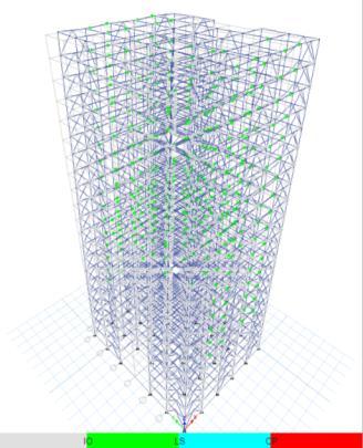
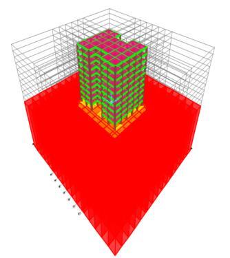
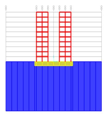
In this analysis two high-rise buildings, G+10 and G+20 storeys, with and without floating columns, situated in seismicZone4andZone5,whicharecharacterizedbyhigh seismicactivity.Thebuildingsarefoundedonsoftsoilwitha

International Research Journal of Engineering and Technology (IRJET) e-ISSN: 2395-0056
Volume: 12 Issue: 05 | May 2025 www.irjet.net p-ISSN: 2395-0072
bearingcapacityof150kN/m²andadepthof30meters.To transfertheloadsfromthesuperstructuretothesoil,amat foundationwithadepthof2.5metersisprovided.Thesoil base is fixed, and surface springs are incorporated at the bottomofthematfoundationtosimulatethesoil-structure interaction. These springs represent the stiffness and dampingpropertiesofthesoil,allowingforamoreaccurate analysisofthebuilding'sbehaviourunderseismicloading.
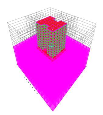
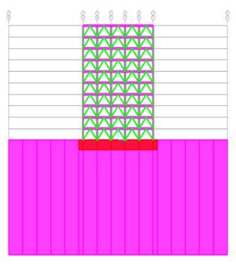
ThemaximumstoreydisplacementofthestructureisinYdirection.HencetheresultsaretakeninY-directionforzone IV & zone V with soft soil condition. Storey displacement variationsareshowninchartbelow.Fromchart11&12it canbeconcludethatbothmodel1inzoneVandmodel2in zone V is showing maximum storey displacement and structurewithbracingsshowsminimumdisplacement.From chart13&14itcanbeconcludethatbothmodel3inzoneV and model 4 in zone V is showing maximum storey displacementandstructurewithbracingsshowsminimum displacement.

-11:Model1storeydisplacement
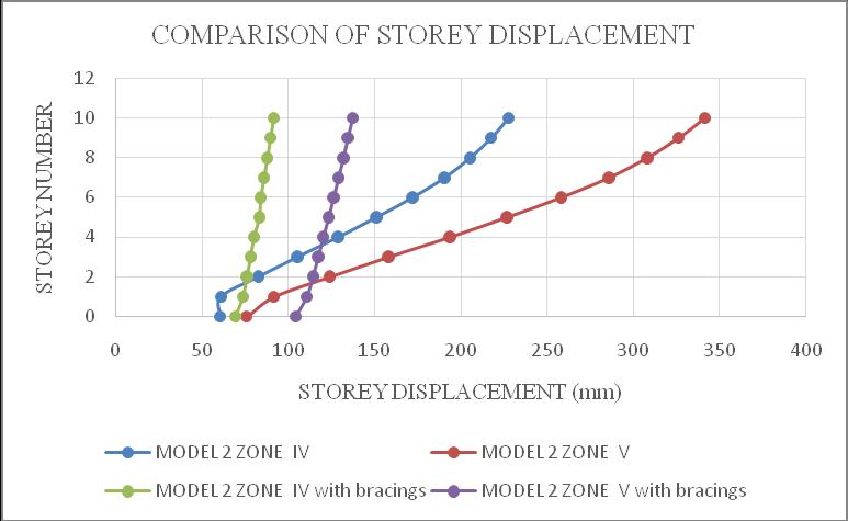
Chart -12:Model2storeydisplacement
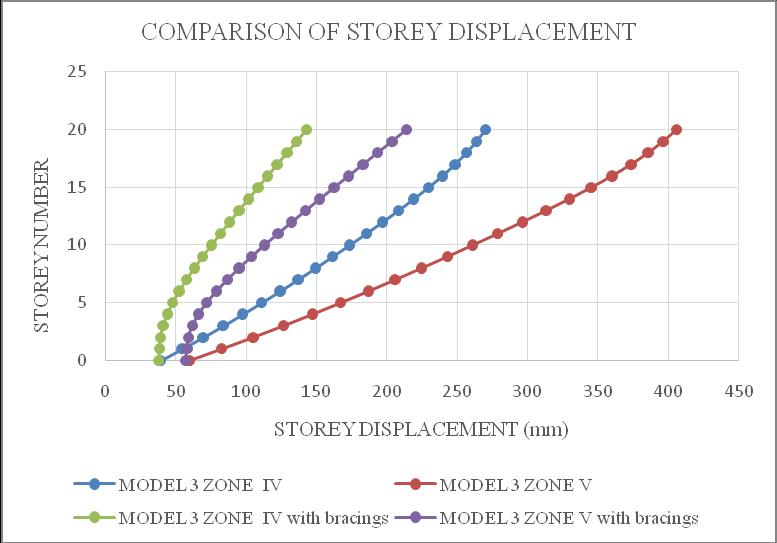
Chart -13:Model3storeydisplacement

International Research Journal of Engineering and Technology (IRJET) e-ISSN: 2395-0056
Volume: 12 Issue: 05 | May 2025 www.irjet.net p-ISSN: 2395-0072

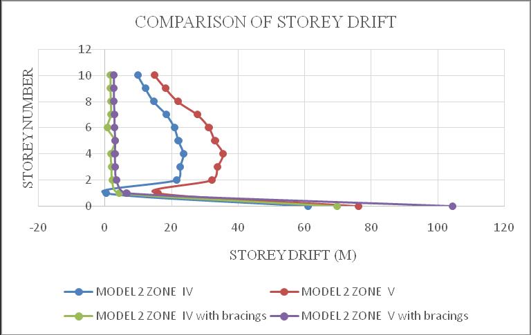
ThemaximumdriftofthestructureisinY-direction.Hence theresultsaretakeninY-directionforzoneIV&zoneVwith softsoilcondition.Storeydrift variationsareshowninchart below.Fromchart15&16itcanbeconcludethatbothmodel 1 in zone V and model 2 in zone V is showing maximum storey drift and structures with bracings shows minimum storeydrift.Fromchart17&18itcanbeconcludethatboth model 3 in zone V and model 4 in zone V is showing maximum storey drift andstructures with bracingsshows minimumstoreydrift.

International Research Journal of Engineering and Technology (IRJET) e-ISSN: 2395-0056
Volume: 12 Issue: 05 | May 2025 www.irjet.net p-ISSN: 2395-0072
Pushoveranalysisisanonlinearstaticanalysismethodused toevaluatetheseismicperformanceofstructures,including soil-structureinteraction(SSI)effects.Thisanalysisaccounts fornonlinearbehaviourofstructuralelements,foundations, and soil, and applies a lateral load pattern to simulate seismic forces. By considering SSI effects, including soil nonlinearity,foundationflexibility,andstructure-foundation interaction, pushover analysis provides valuable insights intoastructure'sseismicperformance.Theanalysisinvolves creatingadetailedmodelofthestructure,foundation,and soil, applying a lateral load pattern, and performing a nonlinear static analysis to determine the structure's response.Theresultscanbeusedtoevaluatethestructure's performance,includingdeformation,damage,andpotential failuremodes.Pushoveranalysiscanhelpidentifypotential weaknessesinthestructure,foundation,orsoil,andinform retrofitting or design decisions to improve seismic resistance.Theresultscanbeconcludedas;
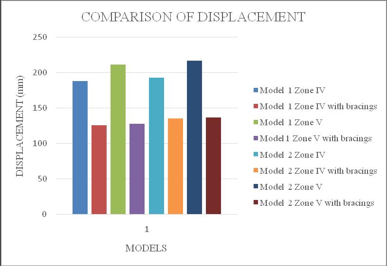
ForbothModel1,Model2,Model3andModel4in Zone IV &Zone V without bracings, each model exhibits different displacement at performance pointindicatingvaryingstructuralcapacities.
All models exceed the collapse prevention performancelevel,itmeansthatthestructurehas exceeded its capacity to withstand seismic forces and is at a high risk of collapse, and significant damageisexpected.Thestructuremayexperience catastrophicfailure,resultinginsignificantdamage, injury or loss of life. Therefore retrofitting is necessary to enhance the structure’s seismic capacityandreducetheriskofcollapse.
AsaretrofittingmeasuressteelinvertedVbracings are provided alternatively at outer side of the structure.
Afterprovidingbracings,allmodelsarewithinlife safety (LS) performance level. It ensures that the structurescanwithstandseismicforceswithsome damage but without compromising life safety. By achievingalifesafetystate,structurescanminimize the risk of injury or loss of life during seismic events.
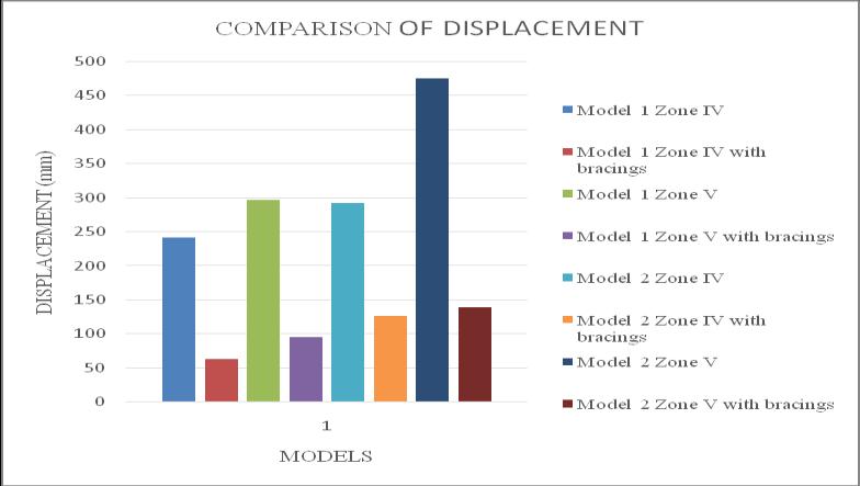
Chart 19:Model1&Model2–comparisonof displacementatperformancepoint
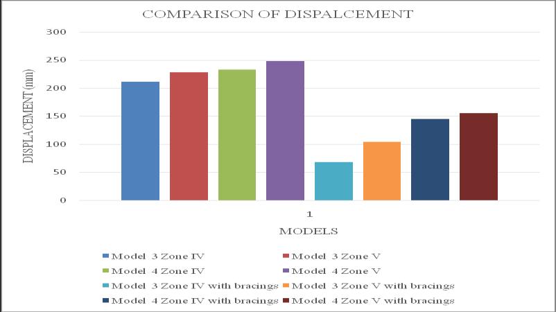
Chart 20:Model3&Model4–comparisonof displacementatperformancepoint
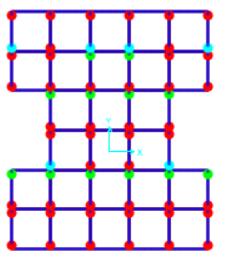
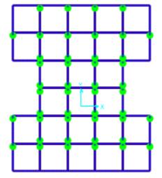
FIG -9:Hingeformation
3. CONCLUSIONS
Structure with floating column shows maximum displacement when compare to the structure withoutfloatingcolumn.
With increase in storey number displacement increase, that is from lower to higher storey displacementincrease.

International Research Journal of Engineering and Technology (IRJET) e-ISSN: 2395-0056
Volume: 12 Issue: 05 | May 2025 www.irjet.net p-ISSN: 2395-0072
When floating column is shifted towards higher storeylateraldisplacementincreases.
Structurewithoutfloatingcolumnshowsminimum storey drift while with floating column shows maximumstoreydrift.
Structurewithoutfloatingcolumnshowsminimum base shear while with floating column shows maximumbaseshear.
Structure in zone V shows higher displacement comparedtostructureinzoneIV.
WheninvertedVsteelbracingsareprovided,storey displacementdecreasesgradually.
Non-linear time history concludes that the time period is higher for structure without floating columnwithbracingscomparedtoequivalentstatic andresponsespectrumanalysis.
In Non-linear time history analysis, storey displacement decreases compared to equivalent staticandresponsespectrumanalysis.
Pushover analysis concludes that the structure withoutfloatingcolumnandwithfloatingcolumn areincollapsepreventionstate.Hencethestructure isunsafe.
After providing inverted V steel bracings alternatively at outer side of the structure, both structures with floating column and without floatingcolumnareinlifesafetystate.
Soilstructureinteractionconcludes,thatthestorey displacementandstoreydriftexceedsthelimitas mentionedinIScode1893-2000.
When pushover analysis is performed for soil structure interaction, the structures exceeds collapsepreventionstateandbecomeunsafe.
When inverted V bracings are provided in entire building , the storey displacement are within the limitandthestructureisinlifesafetystate.Hence thestructuresaresafe.
[1]IS:875(Part1)–1987Codeofpracticefordesignloads (otherthanearthquake)forbuildingsandstructures.
[2]IS:875(Part2)–1987Codeofpracticefordesignloads (otherthanearthquake)forbuildingsandstructures.
[3]IS1893(Part1):2002CriteriaforEarthquakeResistant designofstructures:Generalprovisionsandbuildings.
[4] Preethi , Sudha PH , Maganur D S (2017), “Study The Behaviour Of Seismic Evaluation Of Multistoried Building With Floating Columns” International Journal of Scientific EngineeringandAppliedScience,Volume‐3,Issue‐9.
[5] Sreadha A R, C.Pany, (2020) “Seismic Study of MultistoreyBuildingusingFloatingColumn”International JournalofEmergingScienceandEngineering(IJESE)ISSN: 2319–6378(Online),Volume-6Issue-9,April2020.
[6]HarshaPV,ShilpaValsakumar(2020),”seismicanalysis ofmultistoreybuildingwithfloatingcolumnsusingetabs”, International Research Journal of Engineering and Technology(IRJET)Volume:07Issue:07July2020.
[7] Shivam Wankhade, Prof. M. Shahezad, Dr.N.W.Ingole (2020),” Seismic Analysis of Multi-storied Building with Floating Column”, International Research Journal of Engineering and Technology (IRJET), Volume: 07 Issue: 01Jan2020.
[8] Mohd Khadeer Ahamed, Usha K N (2020),” seismic analysisofmultistoreybuildingwithdifferentpositioningof floating columns” International Research Journal of EngineeringandTechnology(IRJET),Volume:07Issue:10 Oct2020.
[9] Prajakta Agawane1 , Girish Joshi (2021), “Study of BehaviourofMultistoreyBuildingwithFloatingColumn:A Review”,InternationalJournalofResearchinEngineering, ScienceandManagementVolume4,Issue4,April2021.
[10] Mr. Shaikh Aasef Shaikh Nisar, Dr. P.B. Ullagaddi, Dr. G.D. Awchat (2021), “Seismic Analysis of a Multi-storeyed Building with Configuration of Floating Columns”, International Research Journal of Engineering and Technology(IRJET),Volume:08Issue:12Dec2021.
[11]ApurvaM.Dhasade,KrupanjaliS.Bhange ,PratikshaP. JadhaV,ShwetaS.Patil ,PoojaL.Rathod(2022),“seismic analysis of multi storied buildings with floating columns”, Internationaljournalofcreativeresearchthoughts,Volume 10,Issue7July2022.
[12] Amay Ranjan1 , Dr. Vivek Soni2 , Vinay Kumar Singh Chandrakar3 (2024),” Observing the behavior of multistoreybuildingswithfloatingcolumns”InternationalJournal of progressive research in engineering management and science (ijprems) vol. 04, issue 06, June 2024, pp: 17871790.

HEMAVATHIG
M.TECH, EARTHQUAKE ENGINEERING UVCE,BANGALORE,KARNATAKA