
International Research Journal of Engineering and Technology (IRJET) e-ISSN:2395-0056
Volume: 12 Issue: 05 | May 2025 www.irjet.net p-ISSN:2395-0072
International Research Journal of Engineering and Technology (IRJET) e-ISSN:2395-0056
Volume: 12 Issue: 05 | May 2025 www.irjet.net p-ISSN:2395-0072
S D1 , Pallavi K2 , Prajwal R Chavan3, Radhika Nagaraj Dange 4 , Sagar A Patil 5
1 Asst Professor, Department of Civil Engineering, Dr. AIT, Bengaluru 2,3,4,5 UG Students, Department of Civil Engineering, Dr. AIT, Bengaluru
Abstract - Bracings, shear walls, dampers,baseisolationetc are the earthquake resistant techniques adopted to the building to safeguard it from the hazourdous effects of earthquake. The main purpose of this project is to analyze the G+10 residential building with and without Rubber bearing. Two models of the building were created one with rubber bearing and other with fixed support subjected to Dead load, live load and Earthquake load in combination as per IS 875 (part 1&2) and IS 1893-part1. The building considered to be located in zone V. Both the models were analysed and are compared on the basis of storey displacement, storey shear, storey drift, and base shear and are illustrated in the form of chart. The results show that storey displacement, storey shear, storey drift, and base shear values were much less in case of model with rubber bearing when compared with model with fixed support.
Key Words: Earthquake resistant techniques, Rubber bearing,baseisolation,earthquakeload,seismicload
Earthquakes are the most destructive of natural hazards. Earthquake occurs due to sudden transient motion of the ground as a result of release of energy in a matter of few seconds.Theimpactoftheeventismosttraumaticbecauseit affectslargearea,occursallofasuddenandunpredictable.
Vibrations induced in the earth’s crust due to internal or externalcausesthatvirtuallyshakeupapartofthecrustand allthestructuresandlivingandnon-livingthingsexistingon ittheycancauselargescalelossoflife,propertyanddisrupts essentialservicessuchaswatersupply,seweragesystems, communication,powerandtransportetc.
Software usedareAutoCADSoftwareandETABSSoftware. ETABS software used in the project stands for Extended Three-DimensionalAnalysisofBuildingSystems.
AsperIS1893-part1,Indiaisdividedintofivezonesbasedof sevearityinoccuranceofearthquake.
Zone II: A low seismic hazard zone with Zone factor (Z) = 0.10.
ZoneIII:AmoderateseismichazardzonewithZonefactor(Z) =0.16.
ZoneIV:AhighseismichazardzonewithZonefactor(Z)= 0.24.
ZoneV:AveryhighseismichazardzonewithZonefactor(Z) =0.36.
In Base isolation techniques, superstructure is separated fromfoundationusingflexibleinterfacessuchaselastomeric bearings, lead rubber bearings, Sliding systems etc. which allowsthebuidingtomoveindependentlyduringearthquake thusreducingforcetransmittedfromgroundtothebuilding duringearthquake.
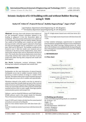
2.1 Flow chart
2.2 Building specifications
Inthisworkfollowingbuildingdetailsareconsidered No.ofstories=10
Height=37 eachbay@3m
SitePlandimensions-100’X50’-8.4”
Location=Bengaluru
ConcretegradeM25
SteelgradeHYSD500
International Research Journal of Engineering and Technology (IRJET) e-ISSN:2395-0056
Volume: 12 Issue: 05 | May 2025 www.irjet.net p-ISSN:2395-0072
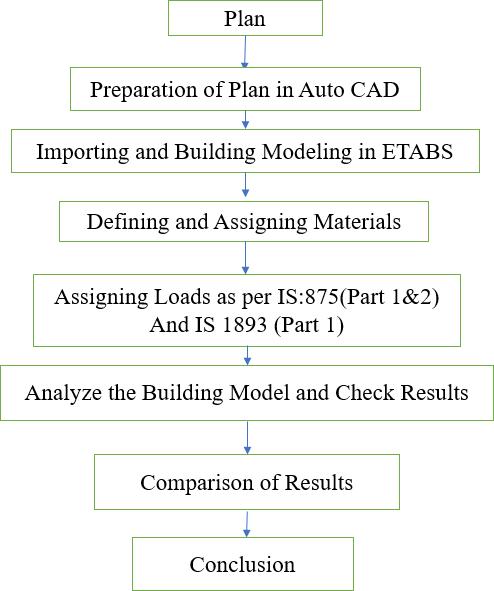
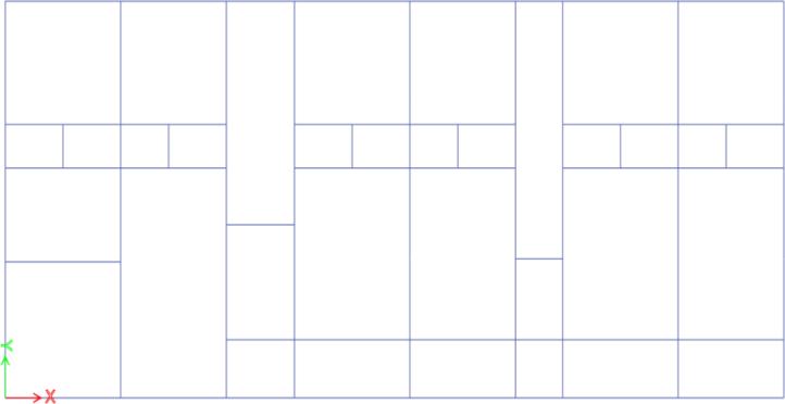
2.3 Plan and column layout
ImportingarchitectureplanfromAutoCADandgeneratethe grids; after getting opened with ETABS we select a new model,andawindowappearswherewehadenteredthegrid dimensionsandstorydimensionsofourbuilding.
:GridgeneratedinEtabs
2.4 Specifying Member Property
Thememberpropertiesaretakenasgiven Thicknessofslab=125mm
Beam=300x200mmColumn=300X750mm
Thememberpropertiesarefirstdefinedandthenassignedto therespectivemembersinEtabssoftware.
Fig-2: Assigning the Beam and Column properties
2.5 Defining of rubber bearing properties
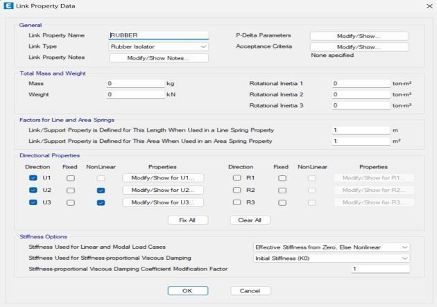
Fig-3: DefiningtheRubberBearingproperty
FortheG+10storey3Dmodelcreated,Fixedsupportswere assignedtoonemodelandrubberbearingswereassignedto anothermodelinsteadoffixedsupport
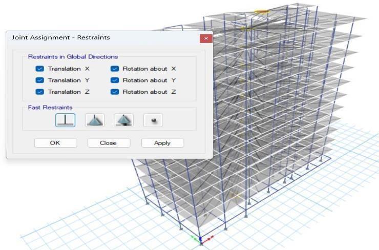
Fig-4: AssigningtheFixedSupport
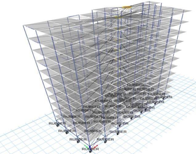
Fig-5: AssigningtheRubberBearing
Deadload,liveloadandearthquakeloadsweredefinedand assignedtoboththemodels,loadcalculationsareasshown below
Deadload
Basedonthebeamandcolumndimensonsassigneddeadload isautomaticallycalculatedbyetabssoftwareitself
Floorfinishload
Weightofmortarbed=1.02KN/m²
Weightofgranite =0.475KN/m²
ThereforeFloorfinish=1.5KN/m²
Liveload
AsperIS875(Part2)-1987forresidentialbuildingliveload intensityisconsideredas2kN/m2
Wallloads
MainWallloads–11.45KN/m
PartitionWallloads-6.25KN/m
Parapetwallloadonterracebeam-3.12KN/m
International Research Journal of Engineering and Technology (IRJET) e-ISSN:2395-0056
Volume: 12 Issue: 05 | May 2025 www.irjet.net p-ISSN:2395-0072
Earthquakeload Earthquake load was defined and assigned in both X and Y directions consideringfollowingparametersasperIS1893-part1
Zone:V
SeismicFactor:0.36
SoilType:II(safesoil)
ImportanceFactor:1
Responsereduction factor:5
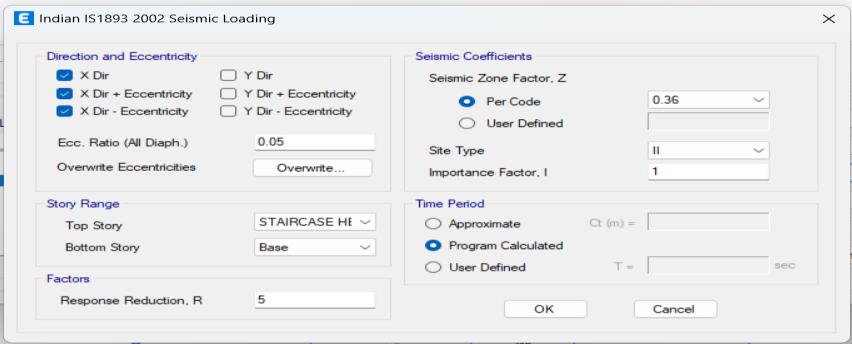
Fig-6: DefiningtheEarthquakeloadinXdirection
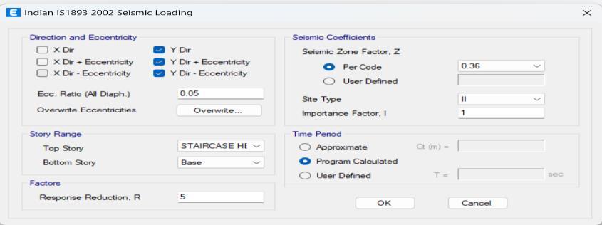
Fig-7: DefiningtheEarthquakeloadinYdirection
2.8 Load combination
Dead load, live load and earthquake load were applied in combination on model with fixed support and also model withrubberbearingconsideringscalefactorof1.2.
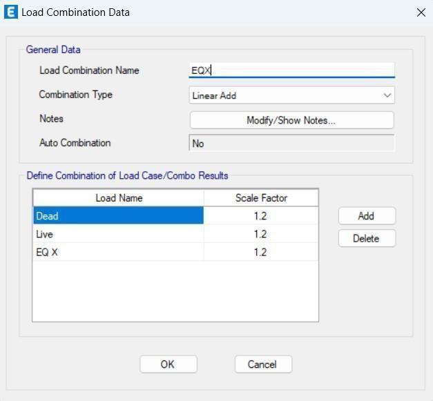
Fig-8: DefiningtheloadcombinationinXdirection
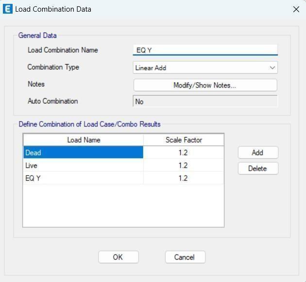
Fig-9: DefiningtheloadcombinationinYdirection
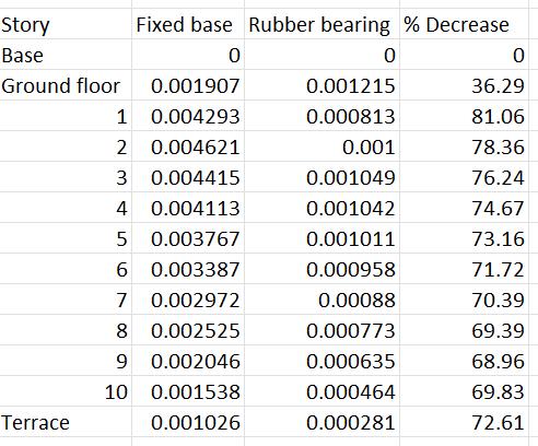
Models are checked for errors and analysed. After the completionofanalysis,resultsofstoreyshear,storeydrift, storeydisplacementandbaseshearinboththemodelswere compared.
Thecomparisionofresultsobtainedarerepresentedbelow bothintableformatandgraphs.Itcanbeobservedthatthe Storey drifts, Storey shear, storey displacement and base shear values for model with rubber bearing is much less whencomparedtomodelwithfixedsupportwhensubjected tocombinedloading.
Table-1: StoreyDriftalongX-DirectionforFixedBaseModel andRubberBearingbaseModel.
International Research Journal of Engineering and Technology (IRJET) e-ISSN:2395-0056
Volume: 12 Issue: 05 | May 2025 www.irjet.net p-ISSN:2395-0072
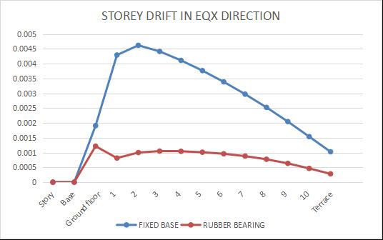
Chart-1: StoreyDriftalongX-DirectionforFixedBaseModel andRubberBearingbaseModel
Table-2: StoreyDriftalongY-DirectionforFixedBaseModel andRubberBearingbaseModel
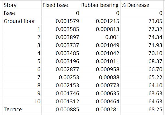
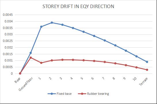
Chart-2: StoreyDriftalongY-DirectionforFixedBaseModel andRubberBearingbaseModel
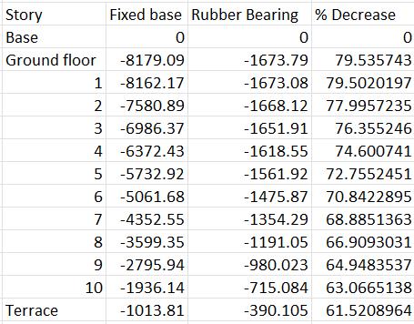
3.2 Storey shear
Table-3: StoreyshearalongX-DirectionforFixedBase ModelandRubberBearingbaseModel
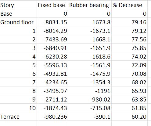
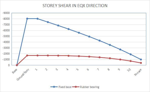
Chart-3: StoreyshearalongX-DirectionforFixedBase ModelandRubberBearingbaseModel
Table-4: StoreyshearalongY-DirectionforFixedBase ModelandRubberBearingbaseModel
International Research Journal of Engineering and Technology (IRJET) e-ISSN:2395-0056
Volume: 12 Issue: 05 | May 2025 www.irjet.net p-ISSN:2395-0072
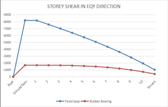
Chart-4: StoreyshearalongY-DirectionforFixedBase ModelandRubberBearingbaseModel
3.3 Storey Displacement
Table-5: StoreyDisplacementalongX-DirectionforFixed BaseModelandRubberBearingbaseModel
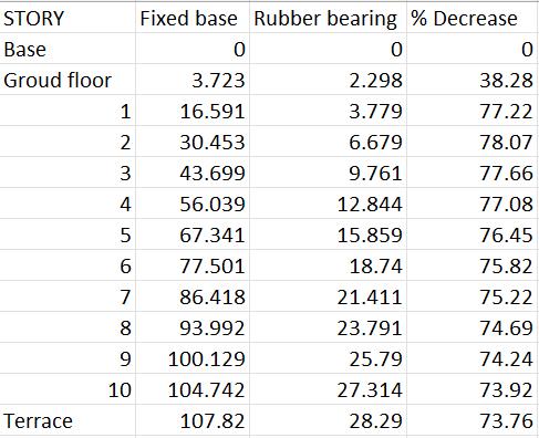
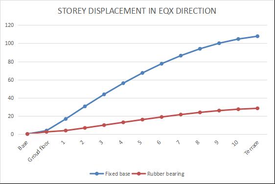
Chart-5: StoreyDisplacementalongX-DirectionforFixed BaseModelandRubberBearingbaseModel
Table-6: StoreyDisplacementalongY-DirectionforFixed BaseModelandRubberBearingbaseModel
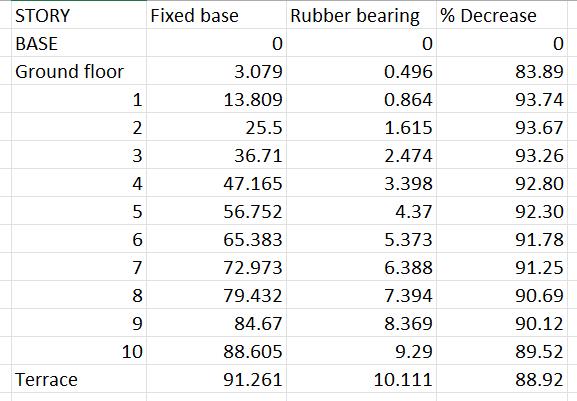
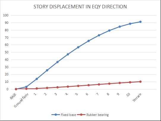
Chart-6: StoreyDisplacementalongY-DirectionforFixed BaseModelandRubberBearingbaseModel
3.4 Base shear
Table-7: BaseshearalongX-DirectionforFixedBaseModel andRubberBearingbaseModel
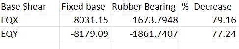
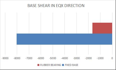
Chart-7: BaseshearalongX-DirectionforFixedBaseModel andRubberBearingbaseModel
International Research Journal of Engineering and Technology (IRJET) e-ISSN:2395-0056
Volume: 12 Issue: 05 | May 2025 www.irjet.net p-ISSN:2395-0072
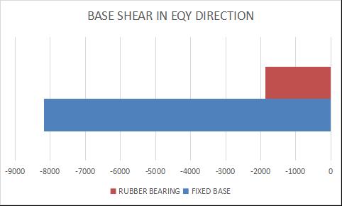
Chart-8: BaseshearalongY-DirectionforFixedBaseModel andRubberBearingbaseModel
Themaximumpercentagedecreaseinthestoreydriftalong EQXandEQYdirectionis87.79%and77.34%
Themaximumpercentagedecreaseinthestoreyshearalong EQXandEQYdirectionis79.16%and79.54%
The maximum percentage decrease in the storey displacement along EQX and EQY direction is 78.07% and 93.67%
Themaximumpercentagedecreaseinthebaseshearalong EQXandEQYdirectionis79.16%and77.24%
Thestoreydisplacement,storeydrift,storeyshearandbase shear values of model with rubber bearing is lower when comparedtomodel withoutrubberbearing,indicatingthe improvedLateralStability
Based on the results,itis recommended toinclude rubber bearing in the design of multi-storey buildings in highseismiczonestoreduceseismicvulnerabilitiesandensure adherencetosafetystandards
The rubber bearing improve the distribution of seismic forces,reducingstressconcentrationsoncolumnsandbeams, thusminimizingtheriskofstructuralfailures.
Dr.Alokkumarjain,Dr.ManishSakhlecha,SumanVerma,et al, “Seismic retrofitting by base isolation and analysing throughE-TABS”InternationaljournalofTrendinResearch andDevelopment(IJTRD)Volume:7(5)|Sep-Oct2020
CenkAlhan,etal.“Modelingofleadrubberbearingsvia3dbasis,sap2000,andopenseesconsidering leadcoreheating modelingcapabilities”InternationalJournalofStructuraland Civil Engineering Research (IJSCER) Volume 7, No 4 | November2018
Mr Ankurvaidya1,Mr ShahayajaliSayyedetal “AResearch onComparingtheSeismicEffectonShearwallbuildingand Without-ShearWallBuilding”InternationalResearchJournal ofEngineeringandTechnology(IRJET)Volume:05Issue:12| December2018
SanketVijayMunot,PBAutade,etal “DesignofLeadRubber Bearing Base Isolator system for high Rise structure” InternationalJournalofCreativeResearchthoughts(IJCRT) Volume:9,Issue:7|July2021.
P B Autade, Rohit Kokane, et al. “Comparitive study on conventionalbuildingwithleadrubberbearingandDamper systems”InternationalJournalofCreativeResearchthoughts (IJCRT)Volume7|July2021
IS:875(Part1),fordeadloads,BureauofIndianStandards, NewDelhi,India
IS: 875 (Part 2), for imposed loads, Bureau of Indian Standards,NewDelhi,India
IS1893(Part1),forseismiczone,BureauofIndianStandards, NewDelhi,India.
RadmilaBSALIC,MihailA.Garevski,ZoranV.Milutinovic,et al “Response of Lead Rubber Bearing Isolated Structure” WorldConferenceEarthquakeEngineering(WCEE)Oct1217,2008,Beijing,China


SnehaSD
Assistantprofessor,departmentof Civil Engineering Dr. AIT Bengaluru
PallaviK
UG Student, department of Civil EngineeringDr.AITBengaluru
PrajwalRChavan
UG Student, department of Civil EngineeringDr AITBengaluru
RadhikaNagarajDange
UG Student, department of Civil EngineeringDr.AITBengaluru
International Research Journal of Engineering and Technology (IRJET) e-ISSN:2395-0056
Volume: 12 Issue: 05 | May 2025 www.irjet.net p-ISSN:2395-0072

SagarApatil
UG Student, department of Civil EngineeringDr.AITBengaluru
© 2025, IRJET | Impact Factor value: 8.315 | ISO 9001:2008 Certified Journal | Page545