International Research Journal of Engineering and Technology (IRJET)
e-ISSN: 2395-0056
Volume: 12 Issue: 03 | Mar 2025
p-ISSN: 2395-0072
www.irjet.net
MULTI-PURPOSE LIQUID FILLING MACHINE USING ATMEGA328P Dr.S.Venkatesan(Prof.EEE)1, Mr.M. Jeyamurugan,AP(Sr.Gr)2, R. Dinesh karthick3,C J Balakumaran4, B. Karthick Raja5 1
Prof/EEE, Department Of Electrical and Electronics Engineering, K.L.N. College Of Engineering, Tamil Nadu, India Prof/EEE, Department Electrical and Electronics Engineering, Velammal College Of Engineering And Technology Tamil Nadu, India 3,4,5 UG Scholar, Department Of Electrical and Electronics Engineering, K.L.N. College Of Engineering, Tamil Nadu, India ---------------------------------------------------------------------***--------------------------------------------------------------------Abstract: 2.SYSTEM ARCHITECTURE 2
This paper presents Multi-Purpose Liquid Filling Machine, a sophisticated hybrid liquid filling system designed for versatility and user-friendliness. Leveraging advanced technology including an ATmega328P microcontroller and a suite of carefully selected components, the Multi-Purpose Liquid Filling Machine offers precise control over liquid filling operations in various industrial settings. This paper outlines the system architecture, key components, operational sequence, and user interface design, highlighting its potential applications and contributions to the field of automated liquid handling.
Keywords: Multi-Purpose Liquid Filling Machine, liquid filling, hybrid system, microcontroller, user interface, automation.
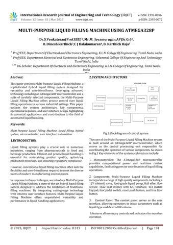
Fig.1.Blockdiagram of control system The core of the Multi-Purpose Liquid Filling Machine system is built around an ATmega328P microcontroller, which serves as the central processing unit responsible for coordinating the operation of various components. As shown in Fig.1 Key elements of the system architecture include:
1.INTRODUCTION Liquid filling systems play a crucial role in numerous industries, ranging from pharmaceuticals to food and beverage production. Efficient and precise liquid handling is essential for maintaining product quality, optimizing production processes, and ensuring regulatory compliance.
1. Microcontroller: The ATmega328P microcontroller
provides computational power and real-time control capabilities, facilitating precise coordination of liquid filling operations.
However, conventional liquid filling machines often lack the flexibility and user-friendliness required to meet the diverse needs of modern manufacturing environments.
2. Components: Multi-Purpose Liquid Filling Machine
incorporates a range of high-quality components, including a 12V solenoid valve, food-grade liquid pump, Hall effect flow sensor, 16x2 LCD display with I2C interface, 4x3 matrix keypad, foot pedal switch, reset push button, and free flow button.
In response to these challenges, we introduce Multi-Purpose Liquid Filling Machine, a state-of-the-art hybrid liquid filling system designed to address the limitations of traditional filling machines. By integrating cutting-edge technology with intuitive user interface features, Multi-Purpose Liquid Filling Machine offers unparalleled versatility and performance in liquid handling applications.
3.
Control Panel: The control panel serves as the user interface, allowing operators to input parameters such as liquid type and desired fill volume. It features all necessary controls and indicators for seamless operation.
© 2025, IRJET
|
Impact Factor value: 8.315
|
ISO 9001:2008 Certified Journal
|
Page 194