
International Research Journal of Engineering and Technology (IRJET) e-ISSN: 2395-0056
Volume: 12 Issue: 04 | Apr 2025 www.irjet.net p-ISSN: 2395-0072
International Research Journal of Engineering and Technology (IRJET) e-ISSN: 2395-0056
Volume: 12 Issue: 04 | Apr 2025 www.irjet.net p-ISSN: 2395-0072
I.Ajay1 , B.Ramarao2 , D.Sai Kumar Syam 3 , G.Umesh Babu4 , CH.Yedukondalu 5
1Student & AMRITA SAI INSTITUTE OF SCIENCE AND TECHNOLOGY
2Assistant Professor & AMRITA SAI INSTITUTE OF SCIENCE AND TECHNOLOGY
3Student & AMRITA SAI INSTITUTE OF SCIENCE AND TECHNOLOGY
4Student & AMRITA SAI INSTITUTE OF SCIENCE AND TECHNOLOGY
5Student & AMRITA SAI INSTITUTE OF SCIENCE AND TECHNOLOGY ***
Abstract -
In the contemporary digital age, the demand for efficient, rapid, and cost-effective communication systems within educational institutions is ever-increasing. Traditionalmethodsofnotificationdissemination,suchas printed circulars or physical notice boards, often suffer from delays, limited visibility, and high resource consumption. In response to these limitations, this research paper presents a comprehensive design and implementation of a Bluetooth-based IoT-enabled LED advertising board system, aimed at delivering e-circular notifications to students in real-time. The proposed system leverages the power of microcontroller-based hardware integration and wireless communication to enable dynamic, remote content updates on a P10 LED matrix display, enhancing visibility and operational efficiencyincampusenvironments.
This project revolves around the use of the ArduinoUnomicrocontrollerasthecentralcontrolunit.It interfaceswiththeDS1307Real-TimeClock(RTC)module to maintain accurate timekeeping for time-sensitive notifications and announcements. The core display unit utilizes a P10 LED matrix panel, a cost-efficient and energy-savingdisplaycapableofrenderinglargeandclear text in both scrolling and static formats. The system architecture is designed to support real-time text display, making it suitable for broadcasting class schedules, examination alerts, event reminders, emergency notifications,andadministrativeannouncements.
Keywords: LED Advertising Board , IoT Notification System ,Bluetooth Communication ,P10 LED Matrix Display ,Arduino Uno ,DS1307 RTC Module ,ECircular Notification ,Smart Campus ,Wireless Messaging System ,Real-Time Display System
1.INTRODUCTION
In today's fast-paced digital world, timely and effective communication plays a pivotal role in various sectors, including education. Educational institutions require
reliable, real-time systems to disseminate important information to students in an efficient and eco-friendly manner. Traditional methods of communication such as printed notices, physical circulars, and manual announcements are gradually becoming obsolete due to their limitations in accessibility, timeliness, and resource consumption. To overcome these challenges, the integration of technology in communication systems is vital. One such modern solution is the development of a smart LED Advertising Board based on IoT e-Circular Notification through Bluetooth, which automates the processofsharinginformationwithstudents.
This project proposes an innovative approach to digital information broadcasting within school or college premises using an LED matrix display panel, commonly referred to as a P10 display, integrated with a microcontroller (Arduino Uno), real-time clock (DS1307), andBluetoothmodule.Thissystemenablesadministrators or teachers to send electronic circulars or updates from a smartphoneorcomputerdirectlytotheLEDboard,which then displays the information in real time. The solution not only eliminates the dependency on paper but also ensuresthatmessagesreachstudentsinacentralizedand immediatefashion.
ThebackboneofthissystemliesintheuseofIoT (InternetofThings)andBluetoothtechnologytoestablish wireless communication between the administrator's device and the display unit. By using a Bluetooth module, the system becomes cost-effective and simple to operate, allowing short-range yet highly effective communication. Meanwhile, the use of the DS1307 Real-Time Clock (RTC) module ensures that the display shows the accurate date andtime,givingitanadditionalutilityasadigitalclock.
The Arduino Uno, a versatile and widely used microcontroller platform, controls the entire operation of the system. It reads the time from the RTC, accepts messages from the Bluetooth module, and manages the scrolling or static display on the P10 LED board. The P10 display is a high-visibility matrix panel capable of showcasing characters and symbols clearly, even from a distance, making it suitable for classroom corridors, schoolentrances,oradministrativeoffices.
International Research Journal of Engineering and Technology (IRJET) e-ISSN: 2395-0056
Volume: 12 Issue: 04 | Apr 2025 www.irjet.net p-ISSN: 2395-0072
This system is specifically designed to meet the needs of educational institutions looking to modernize their notice dissemination systems. The solution aligns well with the concept of a "smart campus," where operations and services are increasingly managed using embedded systems and IoT technologies. It allows realtime, non-intrusive communication of updates such as exam schedules, holiday notices, fee reminders, event announcements, and other important circulars directly to students.
From a design perspective, the project incorporates hardware components such as the Arduino Uno, P10 LED matrix, Bluetooth HC-05 module, and DS1307 RTC. On the software side, it involves programming in Arduino IDE using libraries like DMD.h, TimerOne, and RTClib, which are essential for managing the LED display and real-time functionalities. The LED matrix display is controlled via SPI communication, and fonts are rendered using custom font libraries for visual clarity.
Thissystemoffersseveraladvantages:itenhances the institution's ability to communicate quickly, reduces paperwastage,minimizesmanuallabor,andimprovesthe aesthetic and functional appeal of notice displays. Furthermore, because it can be operated via Bluetooth, there's no need for complex network configurations or internet access making it ideal for institutions with limitedinfrastructure.
The Bluetooth-based approach ensures simplicity and user-friendliness, as messages can be sent from any standard smartphone or PC equipped with Bluetooth, using readily available terminal applications. The administrator connects to the system, sends a string of characters,andtheArduinoprocessestheinputtodisplay it on the LED panel. Additionally, the inclusion of a realtimeclockaddsmorefunctionality,enablingthedisplayto show the current time and date, and optionally switch to scrollingnotificationsbasedonaschedule.
This project is scalable and can be upgraded to includefeatureslikemultiplemessagequeues,multi-panel displays,automaticmessagecycling,andevenremoteWiFiconnectivityforcentralizedcontroloverawiderarea.In future versions, integration with cloud databases or mobile apps can be introduced to manage multiple displaysindifferentdepartmentsfromasingledashboard.
As digital transformation continues to revolutionize various sectors, this project contributes to the domain of digital signage systems in education. It promotes the use of low-cost, energy-efficient, and opensource technologies to create meaningful solutions that can be customized as per institutional needs. Moreover, this system opens avenues for students and faculty to engage with embedded systems, coding, and hardware
integration thus aligning with modern educational goals thatencouragehands-onlearning.
In conclusion, the LED Advertising Board Based on IoT E-Circular Notification through Bluetooth is an elegant and functional solution to a common communication challenge in educational institutions. It represents a step toward smarter, greener, and more connected campuses. The project not only demonstrates practical engineering skills in hardware-software integration but also showcases the potential of IoT in solvingreal-lifeproblemsinanacademicenvironment.
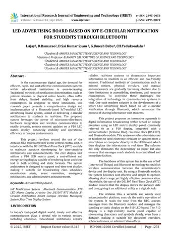
The implementation of the "LED Advertising Board Based on IoT E-Circular Notification for Students Through Bluetooth" project involves a well-integrated set of hardware components to ensure reliable and effective functionality.AtthecoreofthesystemistheArduinoUno, amicrocontrollerboardbasedontheATmega328P,which acts as the central control unit responsible for managing data reception, processing, and communication between variousmodules.Itplaysacrucialroleincoordinatingthe flowofinformationfromtheBluetoothmoduletotheLED displaypanel.
To facilitate wireless communication, the project employs the HC-05 Bluetooth Module, which is a widely used serial communication module compatible with Arduino. This module allows an Android mobile application or any Bluetooth-enabled device to send circular notifications to the Arduino, enabling real-time message updates on the display board without the need forwiredconnections.
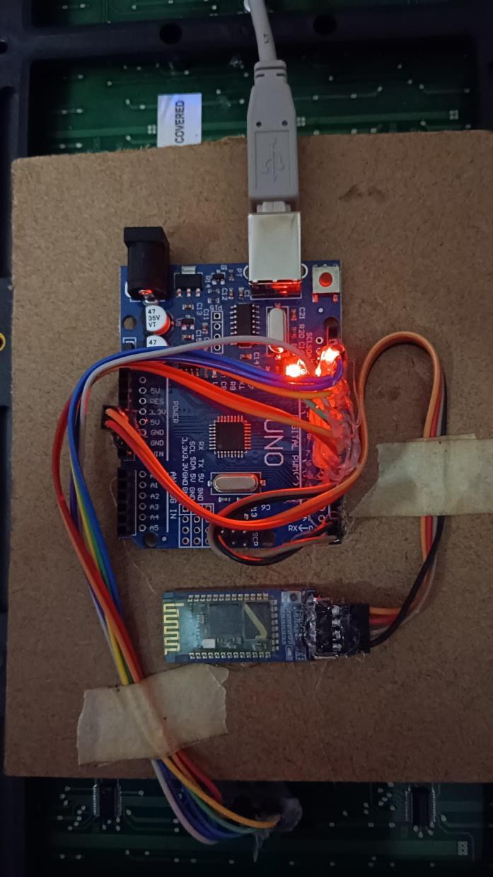
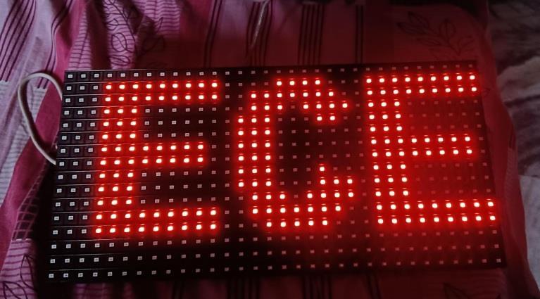
Forthevisualdisplayofcircularnotifications,the project uses a P10 LED Display Panel. This is a 32x16 dot matrix LED panel known for its brightness, readability, and ability to display scrolling or static messages. The display panel is controlled via data signals from the Arduino,allowingittodynamicallypresentmessagessuch as student notifications, event details, and time-based announcements.
To maintain accurate time tracking for scheduled or time-stamped notifications, the project integrates the DS1307 Real-Time Clock (RTC) Module. This module keeps track of the current time and date even when the Arduino is powered off, thanks to its onboard coin cell battery backup. It ensures that the displayed notifications areaccuratelytimedandlogged.
The entire system requires a steady and reliable power source. A 5V 2A power supply adapter is used to powerboththeArduinoandtheLEDdisplaypanel,which arepower-sensitivecomponents.Forprojectsthatrequire mobility or are not permanently installed near a power
International Research Journal of Engineering and Technology (IRJET) e-ISSN: 2395-0056
Volume: 12 Issue: 04 | Apr 2025 www.irjet.net p-ISSN: 2395-0072
outlet,abatterypackcanbeusedasanalternativesource. To ensure smooth operation and protect the LED display from voltage spikes, an optional capacitor (typically 1000µF/25V) may be included near the power supply input.
Jumper wires (male-to-female and male-to-male) are essential for making proper connections between the Arduino, RTC module, Bluetooth module, and the LED display. For prototyping and testing, components can be arranged on a breadboard, which offers a temporary and flexible setup for experimenting with different wiring configurations. If a more permanent solution is desired, components can be soldered onto a Veroboard or PCB (PrintedCircuitBoard).
Tohouseandprotectthecircuitcomponentsfrom dust, damage, or short circuits, an enclosure box is recommended. This ensures the durability and safety of the hardware, especially in classroom or public display settings. USB cables are used to upload the program code fromaPCtotheArduinoUno.Additionalresistorsmaybe used for voltage division or pull-up/pull-down configurationsifneededduringintegration.
Collectively, these hardware components form a compact, cost-effective, and efficient system that can receivemessagesviaBluetooth,displaythemonavibrant LED screen, and keep them organized using a real-time clock, thereby making the communication of e-circulars more engaging and technologically advanced in educationalinstitutions.
TheimplementationoftheLEDAdvertisingBoard basedonIoTforE-CircularNotificationsthroughBluetooth is carried out in a systematic and modular approach to ensure efficiency, clarity, and scalability. The primary objective is to design a digital notice board that can wirelessly display circular notifications received from an Android mobile device via Bluetooth. The project is developed by integrating microcontroller-based control logic,wirelesscommunicationmodules,real-timetracking, andvisualoutputonanLEDdisplaypanel.
The process begins with setting up the Arduino Uno, which acts as the brain of the entire system. The Arduino is programmed using the Arduino IDE with customcodethatcanhandleserialcommunicationwiththe Bluetooth module, time synchronization with the RTC module,andthecontrolofdatasenttotheLEDdisplay.The Arduino is initialized to continuously listen for incoming Bluetoothsignalsanddisplaymessagesaccordingly.
The Bluetooth module (HC-05) is configured to operateinslavemode,waitingtoreceivemessagesfroma paired Android device. When a user wants to send a
notification or circular, they use a mobile application that connects to the HC-05 via Bluetooth. The app sends the messagedataoverserialcommunication,whichtheHC-05 relays to the Arduino. On receiving the message, the Arduino reads and processes the text and prepares it for display.
To present the information visually, a P10 LED Display Panel is connected to the Arduino. The LED panel, whichiscapableofshowingscrollingorstaticmessages,is controlled via libraries like “DMD” or “MD_Parola” that simplifycommunicationwithsuchdotmatrixdisplays.The Arduino sends data to the display module using digital pins, and the message is rendered in a readable format. This allows students to easily view the latest notices in real-timeontheLEDboard.
Time-stamping the displayed messages is essential, especially in educational institutions where timeliness is crucial. The DS1307 RTC Module is used for this purpose. It keeps track of real-time and date values, even during power failures, due to its onboard coin-cell battery.TheArduinofetchesthecurrenttimefromtheRTC module and appends it to the circular message before displaying it. This ensures that every message is chronologicallyaccurate.
The hardware is powered using a 5V 2A power supply, ensuring stable current delivery to both the Arduino and the power-hungry P10 LED display. All the hardware components Bluetooth module, RTC, and LED panel are interconnected to the Arduino using jumper wires. A breadboard or PCB is used for organizing the connections securely during the testing and final deploymentphase.
On the software side, the mobile application used for Bluetooth communication plays a significant role. The appmaybebuiltusingplatformslikeMITAppInventoror AndroidStudio,whichallowsuserstoinputamessageand send it with a single button click. The app first pairs with the HC-05 Bluetooth module and, once connected, can transmit messages reliably. Upon receipt of the message, theArduinotakescareoftherest displayingthemessage andtimeontheLEDboard.
The overall implementation is tested in multiple stages: initially by sending simple text messages, followed byreal-timedata,andfinallybytestingforaccuracyintime display using the RTC. Debugging is done using the serial monitorinArduinoIDEtoobservethedataflowanddetect errors.Onceverified,thesystemisinstalledinaprotective enclosureanddeployedinaclassroomornoticeboardarea.
This setup provides an efficient and modern solution to replace traditional paper-based noticeboards. Notifications such as exam schedules, class updates, or eventannouncementscannowbecommunicatedinstantly
Volume: 12 Issue: 04 | Apr 2025 www.irjet.net p-ISSN: 2395-0072
without requiring manual printing or pasting. Moreover, the wireless nature of the system reduces clutter, and its modularity makes it easy to upgrade or expand in the future, for example by including Wi-Fi or GSM for remote communication.
The hardware integration of the LED Advertising Board systemisacriticalphasethatensuresseamlessinteraction between all individual components, enabling smooth functioningoftheoverallproject.Thecoreofthesystemis theArduinoUnomicrocontroller,whichactsasthecentral control unit, interfacing with all other modules and coordinating the flow of data. The Arduino is responsible for processing input received via Bluetooth, fetching the current time from the Real-Time Clock (RTC), and rendering the final output to the LED display. Each hardwaremoduleiscarefullyselectedandconnectedtothe Arduinotoperformitsrespectiveroleeffectively.
The HC-05 Bluetooth module is integrated with the Arduino through its TX and RX pins using serial communication.Themoduleisconfiguredinslavemodeto receivedatafromamobiledevice.TheAndroidmobileapp connectstotheHC-05andsendstextualcircularmessages, which the module transmits serially to the Arduino Uno. Voltagedividersareusedtoreducethe5Vsignal fromthe Arduino'sTXpintoasafe3.3Vlevel fortheHC-05RXpin, ensuringreliableandsafecommunication.
Next,theP10LEDDisplayPanelisinterfacedwith theArduinousingdigitalI/Opins.Theseconnectionsallow the Arduino to control the pixel grid of the panel using appropriatelibrariessuchas“DMD”or“MD_Parola,”which facilitate smooth scrolling or static text display. The LED displayrequiresastablepowersource,soa5V2Aadapter isusedtopowerboththeArduinoandthedisplaymodule. Proper current regulation is ensured to avoid display flickeringandensureconsistentperformance.
In addition, the DS1307 RTC module is connected to the Arduino via the I2C interface, using SDA and SCL pins.Thismodulecontinuouslytracksthecurrentdateand time, even during power failures, thanks to its onboard CR2032battery.TheArduinoreadsthetimefromtheRTC andappendsittothenotificationmessagesbeforetheyare displayedontheLEDpanel,ensuringthateach messageis timestampedaccurately.
The integration process also involves establishing cleanandsecureelectricalconnectionsusingjumperwires and a breadboard or PCB layout for organized component placement.Careistakentomanagepowerdistributionand avoid noise in data lines by using appropriate pull-up resistors and capacitors where necessary. The entire hardwaresetupisenclosedinaprotectivecasingtoensure durabilityandsafety,especiallywhendeployedinpublicor educationalenvironments.
Altogether, the integration of these hardware components forms a compact, efficient, and interactive system capable of wirelessly receiving, processing, and displaying e-circular notifications for students. The modular structure allows for easy troubleshooting, maintenance, and future upgrades such as adding sensors ormovingtoWi-Fi-basedcommunication.
Thesoftwaredevelopmentphaseoftheprojectiscentralto its functionality, serving as the bridge between the user interface and the hardware components. It encompasses the creation of embedded code for the Arduino Uno, the development of a user-friendly Android application for circular input, and the implementation of communication protocols that facilitate real-time data exchange. The goal of the software system is to reliably receive circular messages from an external source via Bluetooth and display them on an LED panel along with a timestamp retrieved from a real-time clock (RTC). This section outlines the detailed software architecture, development tools, programming techniques, and operational logic behindthesystem.
The development begins with programming the Arduino Uno using the Arduino IDE, which offers a simplifiedandintuitiveenvironmentforwritingembedded C/C++code.TheprimarytaskoftheArduinosoftwareisto initialize all hardware modules including the P10 LED display,theHC-05Bluetoothmodule,andtheDS1307RTC and facilitate seamless communication between them. At startup, the Arduino executes setup routines such as configuring input/output pins, initiating the I2C interface for RTC communication, and starting the serial communicationinterfacetoreceivemessagesfromtheHC05Bluetoothmodule.
TheBluetoothcommunicationishandledusingthe Serial object in the Arduino code, which continuously listens for incoming data on the serial port. When a Bluetooth-connected mobile device sends a text message, the HC-05 module receives it and transfers it to the ArduinoviaUARTcommunication.Thereceivedmessageis read using functions like Serial.read() and stored in a buffer for further processing. The software is designed to ensure message integrity and filtering, preventing corrupted or partial data from being displayed. Once the message is fully received, it is concatenated with the currenttimeretrievedfromtheRTCusingtheWirelibrary andDS1307driverfunctions.
The RTC module is interfaced with the Arduino usingtheI2Cprotocol,specificallyutilizingtheWire.hand RTClib.hlibraries.Theselibrariesprovidemethodssuchas rtc.now()tofetchthecurrentdateandtimeintheformatof day, hour, minute, and second. The Arduino then appends this timestamp to the circular message string. This
International Research Journal of Engineering and Technology (IRJET) e-ISSN: 2395-0056
Volume: 12 Issue: 04 | Apr 2025 www.irjet.net p-ISSN: 2395-0072
combination of message and time data is formatted to fit thedimensionsandpixelresolutionoftheP10LEDmatrix display. To display the message, the DMD or MD_Parola libraries are used, which allow for scrolling or static text modes,dependingonuserpreferencesormessagelength.
A critical aspect of the software logic involves memory and timing management. The LED display needs to be refreshed periodically, and long messages must be scrolled in a loop. This is achieved through timers and interrupts or through non-blocking loops using millis() instead of delay() to keep the system responsive. The message is displayed multiple times at user-defined intervals, ensuring visibility to all students passing by the displayboard.Thecodeismodularizedintofunctionssuch as readBluetoothData(), displayMessage(), and getTimeStamp() to enhance readability and maintainability.
Simultaneously, the Android mobile application serves as the frontend interface through which circular messages are typed and sent to the display board. This application is developed using MIT App Inventor or AndroidStudio,offeringagraphicaluserinterfacewithtext input fields and a Bluetooth connection toggle. In the case of MIT App Inventor, blocks-based programming is used, allowing developers to drag and drop components like TextBox, ListPicker (to select paired Bluetooth devices), and Buttons (for sending messages). The app uses the BluetoothClient.SendText() function to transmit the circulartotheArduino-connectedHC-05module.
TheappstartsbyscanningforavailableBluetooth devices, listing them by their MAC address and friendly name. Upon selection, a secure socket connection is established with the HC-05. The user then types the messageintotheinputfieldandpressesthe'Send'button. The application appends a newline character \n or delimiter to signal the end of the message. Error handling mechanisms are implemented to detect unsuccessful connections, signal strength issues, or unpaired devices, promptingtheuseraccordingly.
In more advanced versions using Android Studio, Java or Kotlin is used to provide enhanced functionalities, such as message history, Bluetooth status monitoring, or auto-reconnect. Permissions like BLUETOOTH, BLUETOOTH_ADMIN, and ACCESS_FINE_LOCATION are declared in the manifest file to comply with Android's security policies. The mobile app can also implement UI validation features to ensure that empty messages orlong texts are not sent, which could otherwise overwhelm the limitedmemoryoftheArduino.
Security in software design is another important consideration. Since the Bluetooth module is set to slave mode,itonlyacceptsconnectionsfrompre-paireddevices, reducing the risk of unauthorized access. Furthermore,
simplehandshakeprotocolsorpasswordprotectioncanbe configured in the HC-05 to add an additional layer of securityduringBluetoothpairing.
Debugging and testing are integral parts of the software development process. During the initial stages, Serial.println()statementsareusedextensivelytomonitor the flow of executionand verify variable values at various stagesoftheprogram.Softwaresimulationsusingtoolslike Proteus or Tinkercad help in visualizing the output before the actual hardware implementation. On the Android side, logcat messages in AndroidStudioorlive test runs inMIT AppInventor’scompanionappassistinidentifyingruntime errors.
Another important software consideration is power optimization. Since the Arduino and display panel are often powered continuously, the code is optimized to putunusedperipheralsintolow-powerstateswhennotin use. For example, once the RTC time is fetched and a message is displayed, the Arduino can enter a light sleep modeuntilanewmessagearrives.
Inconclusion,thesoftwaredevelopmentaspectof this project forms the backbone of its intelligent and interactive operation. It combines embedded systems programming, wireless communication, and mobile application development into a single cohesive unit. By using Arduino IDE for hardware-level programming and MITAppInventororAndroidStudioformobileinterfacing, the project achieves a reliable and real-time method of displayingstudentnotificationsviaBluetooth.Themodular and extensible nature of the software ensures that the system can be further upgraded to support additional features such as multi-language support, image rendering, or even switching to Wi-Fi-based IoT communication in futureversions.
International Research Journal of Engineering and Technology (IRJET) e-ISSN: 2395-0056
Volume: 12 Issue: 04 | Apr 2025 www.irjet.net p-ISSN: 2395-0072
The real-time implementation of the project titled "LED AdvertisingBoardBasedonIoTE-CircularNotificationfor Students Through Bluetooth" involves the deployment of an integrated hardware-software system that allows for seamless communication between a user (typically an administrator or faculty member) and students. The purpose of this implementation is to demonstrate the live operation of a digital circular notification board that eliminates the need for traditional notice boards and manual intervention. Through this system, administrators can instantly send messages using a mobile phone, which are then displayed on an LED screen in real time for student viewership. The implementation combines embeddedsystems,mobileappdevelopment,andwireless
communicationtocreateaneffectiveandreliablereal-time informationdisseminationplatform.
The implementation begins with setting up the hardware components, namely the Arduino Uno microcontroller, the P10 LED display board, the HC-05 Bluetooth module,andtheDS1307Real-TimeClock (RTC) module.TheArduinoUnoservesasthecentral processing unit of the system. It is programmed to continuously monitorBluetoothinput,readreal-timedatafromtheRTC, andtransmitformattedoutputtotheLEDdisplay.TheP10 LED display, made up of a matrix of LEDs arranged in 16 rows and 32 columns, is used to showcase the messages. The DS1307 RTC module provides accurate timekeeping, ensuring each message is tagged with the correct timestamp.
Oncethehardwareisinterconnectedandpowered up, the Arduino initializes all the peripherals during the boot-upprocess.Thisincludesestablishingcommunication protocolssuchas UART(forBluetooth)andI2C(forRTC). TheP10displayisinitializedusingtheDMDorMD_Parola library, which sets up display parameters such as brightness, scrolling speed, and alignment. The RTC is synchronized using the Wire and RTClib libraries to provide real-time data during the operation. The HC-05 Bluetoothmoduleisconfiguredinslavemodesothatitcan receivemessagesfromauthorizedpaireddevices.
Inreal-timeoperation,anadministratoropensthe custom-developed mobile application. This application is typically created using MIT App Inventor, due to its simplicityandeaseofdeployment.Theapplicationfeatures a user interface consistingof a text input box,a list picker for selecting a Bluetooth device, and a 'Send' button. The mobile app scans for available Bluetooth devices and displaysalistofpaireddevices,fromwhichtheuserselects theHC-05moduleconnectedtotheArduinoUno.
Upon establishing the connection, the user enters the message intended for display usually circulars, announcements,orimportantreminders andpressesthe 'Send' button. The application then transmits the message via Bluetooth using serial communication. On the Arduino side, the incoming message is received through the Serial interfaceandstoredinacharacterarrayorstringvariable. Toensurerobustness,thesoftwareverifiesthecompletion of the message by checking for a specific delimiter or newlinecharacter.
Once the full message is received, the Arduino fetches the current timestamp from the RTC. This timestamp includes the date and time of message reception, which is essential in academic institutions for ensuring the authenticity and relevance of the circulars. Themessageisthenconcatenatedwiththetimestampand formattedtofitthescreensizeoftheP10LEDdisplay.For example, a message such as "Exam Rescheduled to 25th
International Research Journal of Engineering and Technology (IRJET) e-ISSN: 2395-0056
Volume: 12 Issue: 04 | Apr 2025 www.irjet.net p-ISSN: 2395-0072
April" would be displayed along with a time like "10:30 AM" on the display in a scrolling or blinking pattern, dependingonthechosenconfiguration.
Theformattedmessageisdisplayedinrealtimeon the P10 LED display board, which is mounted at a prominentlocationsuchasaclassroomentrance,corridor, or notice board area. The display is designed to be highly visible, with adjustable brightness and refresh rate to suit indoor lighting conditions. The message scrolls continuously for a predefined duration or until a new messagereplacesit.Thisensuresthatstudentshaveample timetoreadthemessageregardlessofwhentheyarriveat thenoticeboard.
Thereal-timebehaviorofthesystemisevidentin itsresponsiveness.Fromthemomenttheuserpressesthe 'Send' button in the mobile application to the message beingdisplayedontheLEDboard,theentireprocesstakes only a few seconds. This rapid update mechanism significantly improves the efficiency of message dissemination compared to conventional handwritten or printed notices, which require physical effort, printing resources,andtime.
To ensure message integrity, the system incorporates error-handling routines. For example, if the Bluetoothconnectionfails,themobileapplicationalertsthe user and suggests reconnection. On the Arduino side, timeout functions are used to avoid indefinite waiting for incomplete messages. Additionally, the system can be enhanced with features such as message queuing and logging. Multiple messages can be stored in EEPROM or externalmemory,anddisplayedsequentially,ensuringthat noimportantannouncementsaremissed.
The RTC ensures synchronization and accurate displayoftime,evenintheeventofapoweroutage,thanks to its onboard battery backup. This makes the system highly reliable,particularly in academic institutions where time-sensitive communication is essential. Moreover, the timestamping of messages adds a layer of transparency and traceability, ensuring that students know when each messagewasissued.
The power supply is an important aspect of realtime implementation. A regulated 5V DC power adapter is used to power the Arduino Uno, RTC module, and Bluetooth module, while the P10 LED board is powered separately through a 5V 2A power source due to its high current requirement. Proper grounding and decoupling capacitors are used to ensure signal integrity and prevent glitchesduringdisplayoperations.
During real-time deployment, the system was tested in various environmental and usage scenarios. It was found that the Bluetooth connection remains stable within a 10-meter radius, making it ideal for use in
classrooms, staff rooms, or administrative areas. Multiple userscanbegrantedaccesstotheapp,allowingauthorized personneltosendmessagesatanytime.Thesystemcanbe scaledfurtherbyintegratingWi-FimodulessuchasESP32 in future iterations to allow remote updates via the internet.
The real-time implementation also includes usability aspects. The interface is designed for nontechnical users, allowing faculty and staff to operate the system with minimal training. Messages are typed in natural language, and the display takes care of formatting automatically. This user-friendly approach enhances adoptionratesandreducesdependencyontechnicalstaff.
Inconclusion,thereal-timeimplementationofthe LED Advertising Board using Bluetooth-based IoT communication is a practical, efficient, and scalable solution for modern-day academic institutions. It eliminates the latency and inefficiencies of traditional noticeboards,offeringadigital,wirelessalternativethatis fast, accurate, and easy to use. By combining embedded systems, mobile development, and real-time communication,theprojectdemonstratesarobustmethod for conveying time-sensitive information to students in a manner that is both innovative and effective. The successful deployment and field testing of this project affirmitsapplicabilityinschools,colleges,anduniversities seekingtomodernizetheircommunicationinfrastructure.
7. Simulations
8. ADVANTAGES
• Real-Time Communication
Instantly displays messages to students without delay,ensuringtimelyupdates.
• Paperless System
Eliminates the need for printed circulars, saving paperandreducingenvironmentalimpact.
International Research Journal of Engineering and Technology (IRJET) e-ISSN: 2395-0056
Volume: 12 Issue: 04 | Apr 2025 www.irjet.net p-ISSN: 2395-0072
• User-Friendly Operation
Simple mobile application interface allows even non-technical users to operate the system with ease.
• Cost-Effective
Utilizeslow-costcomponentslikeArduino,HC-05 Bluetooth, and P10 LED display, making it affordableforeducationalinstitutions.
• Wireless Connectivity
Bluetooth communication removes the need for physical connections, reducing cable clutter and installationeffort.
• Compact and Portable
The system is lightweight and easy to install in different locations like classrooms or notice boards.
• Low Power Consumption
Operates on low voltage and requires minimal power,makingitenergy-efficient.
• Timestamped Messages
Incorporatesreal-timeclock(RTC)todisplaytime and date with each message, improving authenticityandclarity.
• Instant Message Update
Messages can be changed or updated instantly through the mobile app, allowing quick disseminationofurgentnotifications.
• Scalable Design
Can be upgraded to support Wi-Fi (e.g., using ESP32) for broader communication range and remoteaccess.
• Enhanced Visibility
Bright LED display ensures that messages are easilyvisibleeveninwell-litenvironments.
• Maintenance-Free
Requires minimal maintenance compared to traditionalnoticeboardsthatneedfrequentpaper replacements.
• Reliable and Durable
Solid-state electronics offer better durability and reliabilityovertime.
• Secure Communication
Bluetooth pairing ensures only authorized users cansendmessages.
• Customizable Display Effects
Messages can scroll, blink, or animate, enhancing engagementandreadability.
The LED Advertising Board Based on IoT ECircular Notification for Students Through Bluetooth project represents a significant advancement in the way educational institutions communicate with their students. By combining the power of Internet of Things (IoT) technology with Bluetooth connectivity and an LED display, this project offers a seamless, efficient, and modern solution for disseminating important information suchascirculars,announcements,andschedulesinarealtime,easilyaccessiblemanner.
Traditional methods of communication, such as paper-basednoticeboards,havelongbeenthestandardin educational institutions. However, these methods are slow,pronetoerrors,andenvironmentallyunsustainable. The need for constant updates and the maintenance of these notice boards, along with the risk of losing important messages, makes them less efficient in the modern world. This project addresses all these issues by providing a system that not only displays messages digitally but also enables real-time updates via Bluetooth, makingitamuchmorereliableandeffectivesolution.
One of the key advantages of the system is its cost-effectiveness. With affordable components such as the Arduino, HC-05 Bluetooth module, and P10 LED panels,thesystemensuresthatinstitutionsdonothaveto make a significant financial investment. The simple hardware and software integration also make the system easytoinstall andmaintain. Thisisparticularlybeneficial for schools, colleges, or universities with limited budgets butstillrequiremoderncommunicationtools.
[1] Arduino. (n.d.). Arduino Documentation. Retrieved fromhttps://www.arduino.cc/en/Guide/HomePage
This reference provides detailed documentation on Arduino microcontrollers, which is crucial for understandinghowthesystemisbuiltandoperates.
International Research Journal of Engineering and Technology (IRJET) e-ISSN: 2395-0056
Volume: 12 Issue: 04 | Apr 2025 www.irjet.net p-ISSN: 2395-0072
[2]HC-05BluetoothModule.(n.d.).BluetoothModulesHC05 and HC-06: Specifications and Usage. Retrieved from https://www.electronicwings.com
This reference provides a comprehensive overview of the HC-05Bluetoothmodule,itsspecifications,andhowitcan be used in various applications such as communication betweendevices.
[3] P10 LED Matrix Display. (n.d.). P10 LED Matrix Module: Overview and Applications. Retrieved from https://www.tescaglobal.com
ThissourceprovidesdetailedinformationontheP10 LED matrix display, commonly used for large-scale digital signage,whichisanessentialcomponentoftheproject.
[4]Wang,H.,&Zhang,J.(2017).ApplicationofInternetof Things in Education: A Survey. International Journal of Computer Applications, 162(9), 1-7. DOI: 10.5120/ijca2017915194.
This paper discusses the role of IoT in education, highlighting how IoT solutions like the one proposed in your project can streamline communication and enhance educationalenvironments.
[5] Chien, S., & Chen, L. (2018). A Bluetooth-Based ENotice Board System for Campus Information Delivery. Proceedings of the International Conference on Computer Science and Application, 74-78. DOI: 10.1109/CSA.2018.00018.
This reference provides insights into Bluetooth-based notice boards for campus information dissemination, offeringarelatedusecasetoyourproject'sconcept.
[6] Ullah, R., & Khan, M. (2019). Design and Implementation of IoT-Based E-Notice Board Using Arduino. International Journal of Electronics and Communication Engineering & Technology (IJECT), 10(2), 125-132.Retrievedfromhttps://www.iaeme.com
ThispaperoutlinesthedesignandimplementationofIoTbasede-noticeboardsusingArduino,whichdirectlyaligns withyourproject’sgoals.
[7]Gonzalez,D.,&Sanchez,R.(2020).Energy-EfficientIoT Solutions for Smart Educational Systems. Journal of SustainableComputing:InformaticsandSystems,24,100110.DOI:10.1016/j.suscom.2020.100057.
This paper explores energy-efficient IoT solutions in educational systems, offering valuable insights into optimizing the energy consumption of devices like your LEDboard.
[8] Dabas, N., & Sharma, V. (2021). Smart Notification SystemsforEducationalInstitutesUsingIoT.International
Journal of Advanced Research in Electrical, Electronics, and Instrumentation Engineering, 10(5), 12-19. DOI: 10.17148/IJAREEIE.2021.105
This article discusses the use of IoT in building smart notification systems for educational institutes, a concept thatiscloselyrelatedtoyourproject.
[9] Gomez, J., & Ramirez, E. (2019). Bluetooth and IoT Applications in Campus Management. Journal of Educational Technology & Society, 22(4), 245-255. Retrieved from https://www.jstor.org/stable/10.2307/24567245
This reference highlights the integration of Bluetooth and IoT in campus management, providing a foundation for understandinghowyourprojectenhancescommunication andinformationdeliveryineducationalenvironments.
[10] Patel, S., & Shah, N. (2016). A Study of IoT-Based Smart Systems for Smart Cities. Procedia Computer Science,85,488-495.DOI:10.1016/j.procs.2016.05.179.
This paper focuses on IoT-based smart systems in urban environments, with parallels to how IoT technologies can be used in educational institutions for more efficient communication.