International Research Journal of Engineering and Technology (IRJET) e-ISSN:2395-0056

Volume: 09 Issue: 08 | Aug 2022 www.irjet.net p-ISSN:2395-0072

International Research Journal of Engineering and Technology (IRJET) e-ISSN:2395-0056
Volume: 09 Issue: 08 | Aug 2022 www.irjet.net p-ISSN:2395-0072
Abstract - This assignment is primarily based at the layout and assembly of an air-operated paper cup making gadget. essentially this undertaking is to don't forget the modern-day problem of expensive gadget for making computer-controlled paper cups used in the modern industries. paper cups specifically include plastic.Plasticisa very riskysubstancein natureandin living things. With the help of this mechanical system papercupsarefabricatedfrompaper,andtheleavesare also used to make cups. After discovering how the presentdaysystemmakespapercups,wecameupwith an inexpensive answer for generating paper cups and bowls.Thissizeofpapercupmakingmachineislooseto matcheverywhereandisverycost-efficientasproperly.
In this gadget we use simple strategies to enhance the efficiency of our undertaking. Punch making plans and dieareusedfortheactualmakingofapapercup.Theair cylinder presents air to the actuator through a directionalmanagevalve.Punchisusedwiththeassistof a directional manipulate valve to govern air strain and supply air to the actuator, because of which the punch backs up and presses on the paper. Paper acquires a countryofdieandtheformationofapapercuphappens. This undertaking is very reasonably priced and minimizesthedamagingresultsofplasticuse.
Key Words: air operated, plastic, fabricated, leaves, inexpensive,efficiency,minimizes
Thisprojectisaboutdesignandfabricationofpneumatic paper cup making machine. The pneumatic paper making press is used to produce different shapes of cup in faster production rate. The principle of operation is the same as the conventional simple press. The difference is only in the type of fluid medium and the typeoffixturesusedandtypeofdrive.
A Pneumaticdeviceisconstantlybetterpreferencethan hydraulic machines for themanufacturingof paper cups.It iscomparativelymorelowin costforproductionof hugeportionsofproductsas
itmakes use ofcompressed airinstead ofhydraulic fluidwhich ishigh-pricedandnow notcleanto controlandstore
Thecutting-edgeproblemisthatpc-controlledpapercup makingdeviceinside themarketarehigh pricedandconsequentlynow notlower pricedfor a teavendorstall. The manufacture of this paper cup makinggadgetisbenefitsto suchdealers Thedevicesizeiscomfytoin shapeeverywhereand iseasilytransportable
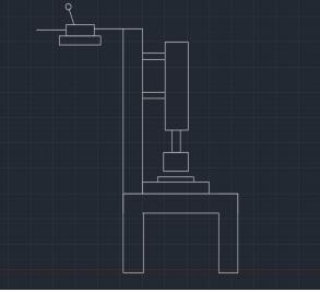
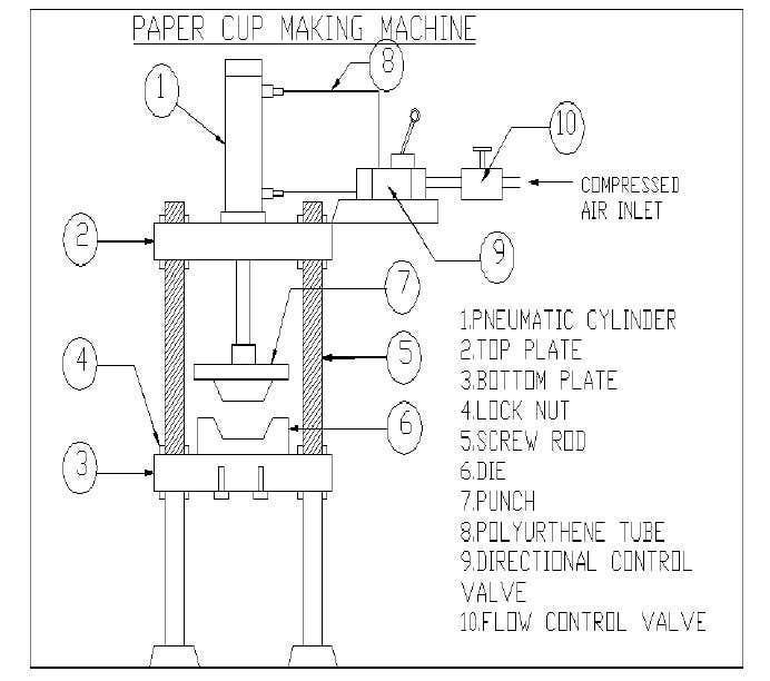
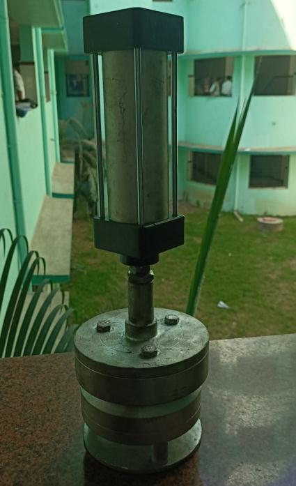
The model is about 550 mm high and width is 300 mm. The assembly consist of actuator, punch, die, direction control valve, flow control valve, connectors and hoses. Thematerialusedforframeisgalvanisediron,fordieset ismildsteel.
1. Design and Fabrication of Pneumatically Operated PaperCup
Author: Vignesh K, Porkalan S, Pradhap Kumar M, PrasannaVenkateshS,PackiyarajM
Figure 1 2DExperimentalsetupdiagram
International Research Journal of Engineering and Technology (IRJET) e-ISSN:2395-0056
Volume: 09 Issue: 08 | Aug 2022 www.irjet.net p-ISSN:2395-0072
In this paper they compared Pneumatic system versus hydraulic system and mechanical system in terms of maintenance, cost and accuracy. Their scope of the project was making the cost of the paper cup making machineaslowaspossibleandincreasingitsefficiency.
 Author: KudakwasheN.Masengere,TawandaMushiri
Thispaperisonthelayoutformanufactureandmeeting of a paper cup making machine for a growing financial system which can be regionally synthetic within an earnings and expenditure that fits to maximum small to medium corporations. A deeper know-how of the paper cupmakingsystemchangedintocarriedoutwiththeaid of the internet, scholarly journals and commercial visits tolocalbusinesses.
maximum risky substance in the environment. With the assist of this air-conditioning machine, paper cups will bemadefromanytypeofpaperandleaves.wecomeup with an inexpensive solution for producing paper cups. Thismissionwillnotablykeepanddecreasetheharmful effectsfromtheusedplastic.Thegadgetlengthmaybeat easetofitanylengthandwillbecleantocarry.
A. DesignofPneumaticCylinder4*2
Forcetobeexertedis80N
Force=pressure×area
Pressureinthecylinder=0.8×0.8bar.
Areaofthepiston((πd2)/4)=force/pressure. =80/80000 =0.001m2D2=(8×0.001)/π Borediameter(D)=0.050=50mm.
B. For Forward Stroke of 50mm bore diameter cylinder
Correspondingroddiameter=25mm
Areaofthepiston=(πd2)/4. =(π×402)/4. =1256.8mm2
This paper is based totally on the manufacture and assembly of an air-cooled paper cup and a dishwasher. paper cups particularly contain plastics. And plastic is the maximum risky substance inside the surroundings. With the assist of this mechanical machine paper cups aremadefromanykindofpaperandtheleavesarealso used to make cups. After learning how the modern gadget makes paper cups, we got here up with an inexpensive solution for making paper cups and bowls. Thislengthofpapercupmakingdeviceisfreetohealthy anywhere and could be very cost-effective as properly. on this system we use the most primary techniques to improvetheperformanceofourundertaking.
The pneumatic machine has been located to be very effective, efficient, and coffee cost. And plastic is the
Force(modified)tobeexerted =pressure×area =80000×1256.8 =100N
C. ReturnStrokeForcecylinder =pressure(areaofpiston–areaofpistonrod) =80000×(1256.8–201)=84N
For working pressure of 0.4bar Extending force = 100NRetractingforce=84N.
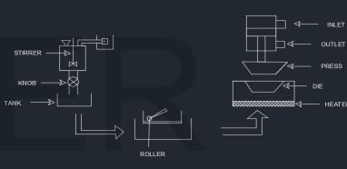
The pneumatic Paper cup making machine consists of the following components to fulfil the requirements to completeoperationofthemachine.
International Research Journal of Engineering and Technology (IRJET) e-ISSN:2395-0056
Volume: 09 Issue: 08 | Aug 2022 www.irjet.net p-ISSN:2395-0072
inaddition,onecanalsowanttomanipulatethequantity of strain and flow fee to provide the desired degree of strength and pace of the actuator. to accomplish these responsibilities, stress valves (flow manipulate valve) are used. stress valves components used to manipulate andmanipulatetheairfloatplace.
CYLINDER:
A cylinder is a double cylinder, which means that air pressure operates in a distinct direction (the front and rear). The air from the compressor passes via the strain controller to the desired quantity by using adjusting its waftcontrol valve.Astress gaugegaugeishookedup to the controller to suggest line stress. The compressed air is then exceeded via a directional manipulate valve to offer air one at a time from both aspect of the cylinder inputandoutlet.thetwohosestaketheoutputandenter ofthemanagevalveandareattachedtoeachendsofthe cylinder the use of connectors. one of the consequences from the course manipulate valve is transferred to the floatmanipulatevalve.
CYLINDER TECHNICAL DATA:
Barrel:Itismadeofcolddrawnaluminiumhonedto 25mm.
Strokelength:100mm
PistonRod:M.S.hardChromeplated
Seals:Nitrile(Buna–N)Elastomer
Piston:Aluminium
Squarebody,Doubleactingcylinder
DIRECTIONAL CONTROL VALVE : (4*3)
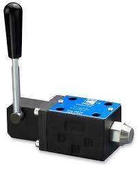
Tomanipulatethemovementofthecylindermovement, the air stress have to be managed, controlled and reversedinapredeterminedorderasandwhilerequired withinthepneumaticgadget.
Theprinciplecapabilitiesofthevalvesare-
•startandforestallthefluidelectricity(air)
•manipulatethedirectionofgowiththeflowof compressedair
•managethedriftrateoftheair
•managethestrainratingoftheair
FLOW CONTROL VALVE:
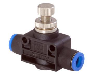
theseareusedto manipulate theflowofairthroughthe valve. A manipulate valve that directs the reception of a particular outside sign, which can be a mechanical, electric or liquid sign signal, adjustments role orientation, or initiatesliquidflow toa specific a part of the air circuit. They can be used to perform obligations whichinclude:
1. Controlling the direction of movement of the actuator Cylinder
2.Selectotherairflowoptions.
3.Tostopandstartairflow
Figure5.Flowcontrolvalve
International Research Journal of Engineering and Technology (IRJET) e-ISSN:2395-0056
Volume: 09 Issue: 08 | Aug 2022 www.irjet.net p-ISSN:2395-0072
Themalepartofreducingtodemiseisreferredtoasthe punch. it is also a removable top limb connected to a pistonwall.Thelayoutofthefistdependsattheplaceto be drilled or included, in addition to the stress required tosuitthepieceofwork.Thepunchtechniquealsorelies upon on the vicinity to be punctured or uncovered or pierced.Thepunchisproductofmildmetallic.
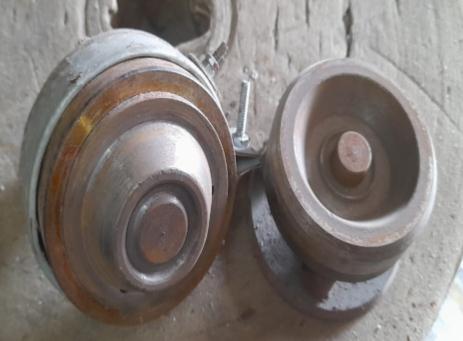
Thedieismountedonthebottomplate.Thedieismade inMildsteel.
Figure 8. designofcupdie
Hoses used in this pneumatic system are made up of polyurethane and blue in color. These hoses can with stand at a maximum pressure level of 10 kg/cm2. Diameterofhoseis8mm.lengthis1m.
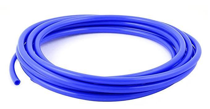
Figure 9. designofcuppunch
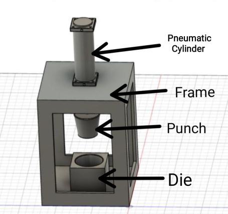
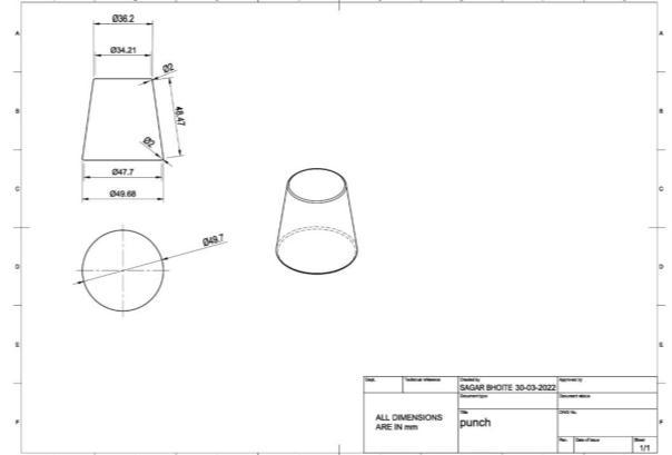
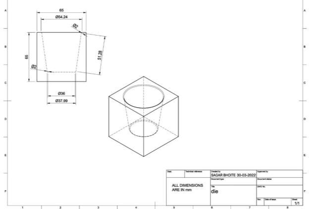
Figure 7. PneumaticHose
Figure 10.Assemblyofmodel
International Research Journal of Engineering and Technology (IRJET) e-ISSN:2395-0056
Volume: 09 Issue: 08 | Aug 2022 www.irjet.net p-ISSN:2395-0072
This makes the punch flow upwards. The cup may be eliminated and the subsequent paper may be located over the estate for the following round and accordingly theprocesscanberepeated.
•Thisproductisoneoftheplasticcupsandplates.
•easytodecomposetheproduct.
• reasonably-priced and without difficulty available substancesareused.
•herbalproduct.
•Nofirethreattroubleduetooverload
•immediateresponseisexecuted.
•smoothtomaintainandrestore
•Unitfeesareminimum
This paper cup holder has a dual pneumatic device, which includes a punch, die, top plate, bottom plate, valve control valve, flow control valve, connectors and pipes. The compressor provides high pressure air to the cylinder parts (a and b) whose flow is controlled by a flowcontrolvalve.
Theairpassesthruthecoursemanagevalve.thisisused topromptthepistonandtodetermineitspathofmotion (aorb).Thepistonisconnectedtotheram.ontheendof the ram's punch is tied. The location of dying in a ram maybemodifiedinoneofakindmethods.
The piston, ram and punch are the shifting elements of this gadget. The dye is constant at the bottom of the machine. The complete unit is targeted in a column (frame).whilstairflowstotheglidemanipulatevalve,its extentisconfinedtothedesireddistinctiveprice.
Then the course control valves control the part of the cylinder that should continue to be according with the feed direction. when it takes part A of the cylinder, it movementstheramtothegroundwiththefist.Fist,fists Paperstoredonadice.
next, directional manipulate valves are activated to permitairtocirculatesegmentBofthecylinder.because of the partial air A is launched from the exhaust valve.
We followed a series of steps that will guide us to solve theproblemsandfulfiltheprojectobjectives.
Firstly we concentrated on designing the dimensions of the various components such as thepunch,dieandtheframe.
We further analysed the loading conditions required for the manufacturing of paper (leaf) cup using the pneumatic system as the main operating
We also tried to find out the different ways in which the pneumatic cups are made in todays industry.
Bytakingasurveyontheinternetwefoundthat the cup making industries have equipments which are much more expensive and are not affordabletothesmallscaleindustriesandthus theyarenotabletomakeprofit.
Wefurthertookalookatthediemanufacturers as well as the frame manufacturers and the pneumaticcylindersupplyingdealers.
We then further collected all the components and we went on towards the assembling of the components.
We faced many difficulties while assembling, as thereweremanyissuesregardingthefittingsof thecomponents.
After facing many difficulties, we finally were able to complete our project successfully with thehelpofourguideProf.Mr.VishwasPalvesir
International Research Journal of Engineering and Technology (IRJET) e-ISSN:2395-0056
Volume: 09 Issue: 08 | Aug 2022 www.irjet.net p-ISSN:2395-0072
who was continuously in contact with us and helpedustocompleteourmodelinaveryshort time period which wouldn’t be able possible withouthim.
Lastly thanks to all the team members for contributingtowardsagreatsuccess.
Thescopeoftheprojectchangedintomakingthepriceof the paper cup system as low as feasible and growing its efficiency. This paper cup making system and dishwasher offers the cup necessities approximately 85% performance. it's far clear that the mission is economicallypossibleinallrespects,aswellasthepaper refreshunit.
The pneumatic machine is better than the hydraulic device and mechanical gadget in terms of renovation, cost, protection and accuracy. The device frame is carefully designed and examined when it meets the requirements.
[1] Sanchit Gaikwad, Amol Kalokhe, “automatic paper plate making machine”, global magazine for research in Engineering packages, ISSN:2494-9150,vol02,pp.1-5,(2017).
[2] (Rose-Hulman ), D.S.(2008). “creation to design for (price effective) meeting and manufacturing”. Retrieved 12/01/2017,2017 from http://me.gatech.edu/files/capstone/L071ME4 182DFA.
[3] Aurabh rathod, Nitin H Wankhede, “design of manually operated transportable paper recyclinggadget”,ISSN:2321-8169,(2016)
[4] IJSRD - international magazine for clinical studies&improvement|Vol.6,trouble02,2017 |ISSN(online):2321-0613,VigneshK1Porkalan PradhapKumarPrasannaVenkateshPackiyaraj
[5] Ashwini Masurkar, Rushikesh Kolape, Sneha more, Yogesh Mane, prof. Dinesh Pargunde, global magazine of scientific & Engineering researchextent10,difficultyfive,canalso-2018 ISSN2229-5518
First Sagar Bhoite Author Author name is currently pursuing bachelor’s degree in mechanical engineering andcompletedDiplomainmechanicalengineeringinthe year2020.
Second Rohit Bhoir Author Author name is currently pursuingbachelor’sdegreeinmechanicalengineering.
Third Vaibhav Davale Author Authornameiscurrently pursuingbachelor’sdegreeinmechanicalengineering.
Fourth Ayush Singh Author Author name is currently pursuingbachelor’sdegreeinmechanicalengineering.