International Research Journal of Engineering and Technology (IRJET) e-ISSN: 2395-0056

Volume: 09 Issue: 08 | August 2022 www.irjet.net p-ISSN: 2395-0072
International Research Journal of Engineering and Technology (IRJET) e-ISSN: 2395-0056
Volume: 09 Issue: 08 | August 2022 www.irjet.net p-ISSN: 2395-0072
3
1 Student, Department of Mechanical Engineering, Amrita School of Engineering, Kollam, Kerla, India
2Student, Department of Mechanical Engineering, Amrita School of Engineering, Kollam, Kerla, India
3Assistant Professor, Department of Mechanical Engineering, Amrita School of Engineering, Kollam, Kerla, India ***
Abstract- A clutch is a mechanical device that transfers rotation from a shaft to the other. Contact clutches are widely utilized in the gearbox transmission system of automobiles. Clutches serve as a linkbetweenthedrivingand driven shafts. Multi-plate clutches are used in heavy weight vehicles as it is near to impossible to transmit torque with single friction plate. One of the most crucial assignments in friction clutches is the selection of the preferred friction lining material to attach to the clutch plates to transmit maximum amount of torque. We use the uniform wear hypothesis to design a multi plate clutch in this paper. We havedesigneda 3D model usingSolidworks 17.0 software for the clutch and Ansys Workbench 19.0 to study stress, strain, total deformation, Maximum Shear stress, Elastic strain for friction material made of Titanium carbide in comparison with Carbon Fiber.
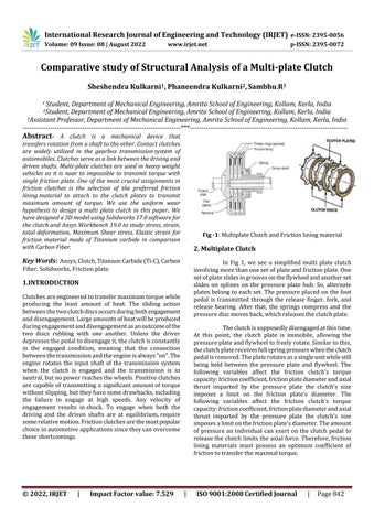
Key Words: Ansys,Clutch,TitaniumCarbide(Ti-C),Carbon Fiber,Solidworks,Frictionplate
Clutchesareengineeredtotransfermaximumtorquewhile producing the least amount of heat. The sliding action betweenthetwoclutchdiscsoccursduringbothengagement anddisengagement.Largeamountsofheatwillbeproduced duringengagementanddisengagementasanoutcomeofthe two discs rubbing with one another. Unless the driver depressesthepedaltodisengageit,theclutchisconstantly in the engaged condition, meaning that the connection betweenthetransmissionandtheengineisalways"on".The engine rotates the input shaft of the transmission system when the clutch is engaged and the transmission is in neutral,butnopowerreachesthewheels.Positiveclutches are capable of transmitting a significant amountof torque withoutslipping,buttheyhavesomedrawbacks,including the failure to engage at high speeds. Any velocity of engagement results inshock. To engage when both the driving and the driven shafts are at equilibrium,require somerelativemotion.Frictionclutchesarethemostpopular choiceinautomotiveapplicationssincetheycanovercome theseshortcomings.
Fig -1:MultiplateClutchandFrictionliningmaterial
In Fig 1, we see a simplified multi plate clutch involvingmorethanonesetofplateandfrictionplate.One setofplateslidesingroovesontheflywheelandanotherset slides on splines on the pressure plate hub. So, alternate plates belong to each set. The pressure placed on the foot pedal is transmitted through the release finger, fork, and release bearing. After that, the springs compress and the pressurediscmovesback,whichreleasestheclutchplate.
Theclutchissupposedlydisengagedatthistime. At this point, the clutch plate is immobile, allowing the pressureplateandflywheeltofreelyrotate.Similartothis, theclutchplatereceivesfullspringpressurewhentheclutch pedalisremoved.Theplaterotatesasasingleunitwhilestill being held between the pressure plate and flywheel. The following variables affect the friction clutch's torque capacity:frictioncoefficient,frictionplatediameterandaxial thrust imparted by the pressure plate the clutch's size imposes a limit on the friction plate's diameter. The following variables affect the friction clutch's torque capacity:frictioncoefficient,frictionplatediameterandaxial thrust imparted by the pressure plate the clutch's size imposesalimitonthefrictionplate'sdiameter.Theamount of pressure an individual can exert on the clutch pedal to releasetheclutchlimitstheaxialforce.Therefore,friction lining materials must possess an optimum coefficient of frictiontotransferthemaximaltorque.
International Research Journal of Engineering and Technology (IRJET) e-ISSN: 2395-0056
Volume: 09 Issue: 08 | August 2022 www.irjet.net p-ISSN: 2395-0072
1. Under working conditions, a relatively high coefficientoffriction.
2. Reasonably good short-term energy absorption capacity.
3. Mustbeabletoendurehottemperaturesbrought onbyslipping
4. Shouldkeepitsfrictionalcharacteristicsthroughout itsoperatinglife.
5. Must endure a pressure plate's high compressive load.
6. Must be extremely resistant to wear effects such scoring,galling,andablation.
7. Oilandmoistureshouldhavenoeffectonit.
8. Theshearstrengthshouldbesufficienttotransmit torque.
9. Goodbasemetalcompatibilityacrosstheworking temperaturerange.
10. Itshouldbeabletodissipateheatwell.
In this study, we compare two distinct friction lining materials,Ti-CandCarbonFiber.Boththesematerialshave high-performance metallic composite material made of carbon.Itcanendurehighenergyinputsandissuitablefor both dry as well as oil-immersed application domains, making it an alternative to often used sintered metallic materials as friction lining. It isn't abrasive to the counter material, operates quietly, and can resist high stresses. Despiteextremetemperatures,wearisminimal
Power = 10.6KW @ 11000 rpm and Torque = 13.2 Nm @ 8500rpm
Table-1Propertiesoffrictionliningmaterials
Property Ti-C CarbonFiber
Density(g/cc) 4.92 1.60
Tensile Modulus (GPa) 400 70
Poissoncoefficient 0.187 0.10
Yield Strength (MPa) 258 600
Coefficient of friction 0.35 0.32
Ti-Consteelwasusedasthematerial
R1 andR2 aretheouterandinnerfrictionfaceradiuses. R1 =0.056mandR2 =0.045m k=noofpairsofcontactsurfaces k=k1 +k2 –1
Wherek1 andk2 areno ofdiscsondrivinganddrivenshaft k1 =6andk2 =4;k=9
Takingintoaccounttheuniformwearhypothesis,wearingis dependent on the magnitude of the pressure “P” and the angular velocity of the friction plate, both of which are dependentonR,
Asaresult,havinganevenrateofwear(P)x(R)iscontinual
ForuniformwearR=0.5*(R1+R2)
WhereR=averageoftheradiusoffrictionmaterial
R=(0.056+0.045)/2=0.0505m
Torque(T)=µ*W*R*k
Where, µ = friction coefficient and W = Clamping force or LoadactingAxially.
13.2=(0.35)*(W)*(0.0505)*(9)
W=82.97N
Now,fromuniformwearhypothesis, W=(2π)*(PmaxR2)*(R1–R2)
Where, Pmax= maximum pressure between the contacting surfaces
95.52=(2π)*(Pmax x0.045)*(0.056–0.045)
Pmax=26,676.94N/mm²
The values of W and Pmax are also calculated for another materialCarbonFiber(µ=0.32),usingthemethoddescribed above.
W=90.75N
Pmax=29,181.32N/mm2
ThemodellingiscarriedoutinSolidworks17.0.A same model of the Multi plate clutch is designed and assembled.Theburstviewofthemultiplateclutchassembly isshownintheFig2.
International Research Journal of Engineering and Technology (IRJET) e-ISSN: 2395-0056
Volume: 09 Issue: 08 | August 2022 www.irjet.net p-ISSN: 2395-0072
Fig3showsthesingleplateofthemultiplateclutch assembly on which the friction lining materials, Ti-C and Carbonfiberarepresent.TheplateismadeupofStructural stainlesssteel.Thefrictionliningmaterialsareattachedto theclutchplateusingdifferentadhesives.
Fig-4: TotalDeformationusingTi-Cfrictionlining
Fig -3: Singeclutchplatewithfrictionlining
Usingcomputingmethods,themaximumpressureisapplied tothefrictionplate.Ansysisusedtocomputetheresultsof Maximumshearstress,TotalDeformationandElasticstrain arecomparedbetweentwomaterials.
In ANSYS structural analysis is done for each node individually, after solving the results of each node it is compiledtogivetheresult.
Underdynamicconditionsforstructuralanalysis,figures4 and5showthetotaldeformationsofclutchplatewithTi-C andCarbonFiberrespectively
Fig-5: TotalDeformationusingCarbonFiberfrictionlining
6.2 Maximum Shear Stress
Under dynamic conditions, figures 6 and 7 show the MaximumshearstressofclutchplatewithTi-CandCarbon Fiberrespectively
value:
Fig-6: Maximumshearstress usingTi-Cfrictionlining
International Research Journal of Engineering and Technology (IRJET) e-ISSN: 2395-0056
Volume: 09 Issue: 08 | August 2022 www.irjet.net p-ISSN: 2395-0072
Table2-ComparisonbetweenTi-CandCarbonfiber Property
Ti-C CarbonFiber Total Deformation(mm) 4.5721e-7 2.7798e-6
Maximumshear stress(MPa) 0.021069 0.020221
Maximumshear elasticstrain 1.2505e-7 6.3551e-7
6.3 Maximum shear elastic strain
Under dynamic conditions, figures 8 and 9 show the Maximumshearelasticstrain ofclutchplatewithTi-Cand CarbonFiberrespectively Fig-8:
AccordingtothefindingsinTable2,itcanbeconcludedthat clutchplatesbuiltusingfiberasthefrictionliningmaterial exhibitlessoveralldeformationandmaximumelasticstrain than clutch plates created with titanium carbide. Upon comparisontoTitaniumCarbide,themaximumstressthat can be created in a clutch plate's friction material with Carbon Fiber is lower for the same amount of torque. Therefore,itispossibletoconcludethatclutchplateswith carbonfiberfrictionmaterialoperatebetterthanthosewith titaniumcarbide.
[1] S.JayaKishore,M.LavaKumar,“StructuralAnalysisof Multi-PlateClutch”,InternationalJournalofComputer TrendsandTechnology(IJCTT)–volume4Issue7–July 2013.
[2] SagarOlekar,KiranChaudhary,AnilJadhav,P.Baskar, “Structuralanalysisofmultiplateclutch”IOSRJournalof MechanicalandCivilEngineering(IOSR-JMCE)Volume 10,Issue1(Nov.-Dec.2013),PP07-11
[3] Mamta G. Pawar, Monarch K. Warambhe, Gautam R. Jodh,“DesignandAnalysisofClutchUsingSinteredIron asFrictionMaterial”,InternationalJournalofInnovative Technology and Exploring Engineering (IJITEE) ISSN: 2278-3075,Volume-3,Issue-7,December2013.
[4] AnilJadhav,GauriSalvi,SantoshUkamnal,Prof.P.Baskar, “Static Structural Analysis of Multiplate Clutch with Different Friction Materials”, International Journal of EngineeringResearchandTechnology,Vol.2,Issue11, November–2013.
[5] Modelling and Analysis of Multi-Plate Clutch by AniruddhaJoshi(IJSR).
As shown in table 2, a comparison is made between the frictionliningmaterialsTi-CandCarbonfiberforthedynamic structuralanalysisoftheclutchplate
[6] DesignandAnalysisofFrictionClutchPlateusingAnsys byS.Gouseseemabegum,A.Balaraju.
[7] Virendrakumarpatel,GopalSahu,PrakashKumarSen, Ritesh Sharma, Shailendra Bohidar, “Review on Wear
International Research Journal of Engineering and Technology (IRJET) e-ISSN: 2395-0056
Volume: 09 Issue: 08 | August 2022 www.irjet.net p-ISSN: 2395-0072
Analysis of Different Types of Clutch Materials”, InternationalJournalofResearchinAdventTechnology, Vol.3,No.11,November2015E-ISSN:2321-9637.
[8] Finite Element Analysis of Multi plate clutchUsed In Power Plants 1M. Suri Babu, 2 Dr.B.Subbaratnam 1M.Tech student, 2Professor, Dept of Mechanical Engineering,Kits,Markapur,A.P,India.
[9] Structuralandthermalanalysisofaboilerusingfinite elementAnalysisD.KondayyaDepartmentofMechanical Engineering, Author Correspondence: Department of MechancalEngineering,SreenidhiInstituteofScience& Technology,Ghatkesar,Hyderabad–501301.
[10] Designandanalysisoftheprototypeofboilerforsteam pressure control 1Akanksha Bhoursae, 2 Jalpa Shah, 3Nishith Bhatt Institute of Technology, Nirma University, SG highway, Ahmedabad-382481,India 3Essarsteelslimited,Hazira,Surat-394270,India.
[11] Lou Roussinos, P. E., “Boiler Design and Efficiency” [online], Available: http://www.forestprod.org/drying06williamson .pd f, Accessed:September1,2010.
[12] Murdock,K.L.,“3dsmax9Bible,WileyPublishingInc. Indianapolis,Indiana,2007.
[13] Nagpal, G. R. E J Berger, F Sadeghi, C M Krousgrill. Analytical and numerical modeling of engagement of rough, permeable, grooved wet clutches [J].Journal of Tribology,1997,vol.119,pp.143-148
[14] SteamPressureReduction:OpportunitiesandIssuesby U.SDeportmentofenergy.
[15] Charles C. Tillotson, PowerTransmission Clutch, US 850981,grantedApr.23,1907.
[16] William Lautenschlager, Friction Clutch, US 1439314, grantedDec.19,1922.
[17] E J Berger, F Sadeghi, C M Krousgrill. Analytical and numericalmodelingofengagementofrough,permeable, groovedwetclutches[J].JournalofTribology,1997,vol. 119,pp.143-148.
[18] JAnaldoM.English,FrictionClutch,US255957,granted Apr.41882.
2022, IRJET | Impact Factor value: 7.529 | ISO 9001:2008 Certified Journal |