ANALYSIS AND EVALUATION OF COEFFICIENT OF DISCHARGE ON ORIFICE PLATE AND FLOW NOZZLE
Assistant Professor, Department of Mechanical Engineering, Guru Nanak Institute of Technology, Khanapur, Telangana, India1 U.G. Student, Department of Mechanical Engineering, Guru Nanak Institute of Technology, Khanapur, Telangana, India2,3,4 ***

Abstract An orifice plate is a tool used for measuring flow charge. Either a volumetric or mass float fee can be decided. The Flow Nozzle is a flow tube consisting of a smooth convergent phase leading to a cylindrical throat region. It is used for measuring the float quotes of the liquid discharged into the ecosystem. The differential strain gadgets which include orifice plates and drift nozzles are substantially used in numerous industries with a purpose to estimate the mass float rate strolling thru a conduit by way of correlating the measured stress loss, speed loss and the mass waft fee. The present work is directed toward to the observe of coefficient of discharge of an orifice plate and float Nozzle. Catia is used for designing the orifice plate and glide nozzle and Ansys is used for analysis of the orifice plate and go with the flow nozzle. Computational Fluid Dynamics (CFD) is used to are expecting the go with the flow capabilities in the orifice plate and drift Nozzle. Outcomes of the CFD simulations in phrases of profiles of pace, strain and coefficient of discharge are discussed in detail. As the diameter of orifice and glide nozzle will increase, the coefficient of discharge also will increase. Flow nozzle has excessive coefficient of discharge than orifice plate. Furthermore, the values of theoretical coefficient of discharge have less deviation from the analytical coefficient of discharge.
Key Words: Computational Fluid Dynamics (CFD), Orifice plate, Flow Nozzle, Velocity, Pressure, Coefficient of discharge
1.INTRODUCTION
1.1 Orifice Plate
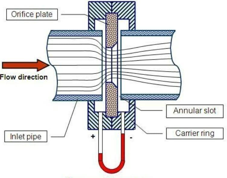
Orificeplates areprimary flowelements, which isused for measuring the flow rate, either a volumetric or mass flowratemaybedetermined.Anorificeplateisatypeof differential pressure device with a hole in it, which is usuallyplacedinapipe.Whenafluid(whetherliquidor gaseous) passes through the orifice, its pressure develops somewhat upstreamoftheorificehoweveras theliquidisconstrainedtoconvergeandpassedthrough the hole of orifice, the velocity increases and the fluid
pressure decreases. A somewhat downstream of the orifice the flow reaches its point of maximum convergence,wherethevelocityreachesitsmaximumand thepressurereachesitsminimum.
Fig.1: Orificeplate[4]
Beyondthat,whentheflowextendsthevelocityfalls,andthe pressure rises. By measuring the difference in fluid pressure across upstream and downstream of the plate, the flow rate canbeobtained fromBernoulli’s principle which states that there is a connection between the pressureandthevelocity of the fluid. When the velocity rises,the pressure falls and viceversa.Theorificeplateis commonlyusedincleanliquids, gasandsteamservice.Itis availableforallpipesizes,anditis verycosteffectivefor measuringfluidflowsinlargerpipes.[5]
1.2 Flow Nozzle
FlowNozzlehasasmoothellipticalinletmaintoathroat section with a sharp outlet. Restriction in the fluid flow causesapressuredrop,whichrelatestotheflowrateby applyingBernoulli’sequation.
The flow nozzles are a flow tube consisting of a easy convergentsectionmaintoacylindricalthroatplace.Throat issmallestsectionofthenozzle.Pressuretapsareplacedon the upstream side of the nozzle plate and at the downstreamsideofthenozzleoutlet.
ISSN: 2395 0056
Volume: 09 Issue: 07 | July 2022 www.irjet.net p-ISSN: 2395-0072

2. LITERATURE SURVEY
Saeid Mokhatab et.al.Thispapersaysthatorificeplateis themostcommonlyusedflowsensor,butitcreatesarather largenonrecoverablepressureduetotheturbulencearound the plate, leading to high energy consumption. An orifice platehasanopeningholethatissmallerthanthediameterof thepipe.Theordinaryorificeplatehasaconcentric,sharp edged opening. Because of the smaller area, the fluid speed increases to cause a corresponding lower in pressure. The flow rate may be calculated from the measuredpressuredropthroughouttheorificeplate.[1]
Fig. : Flownozzle[6]
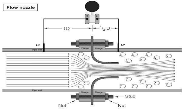
Theymaybeintheformofanannularring,i.e.,equally spaced holes related collectively which open in to the pipeline, or in the form of single holes drilled into the pipeline.[7]
1.3 Modelling
It is the process of converting 2 dimensional/cartoon diagram into three dimensional model the usage of software program’s which convert a diagram right into a mathematical model and venture on show like a model.Thepurposeof whichistomakeaselectedpart or function world less complicated to apprehend, outline, quantity,visualizewiththeaidof referencingit tocurrentandtypicallytypicallyacceptedknow how.
1.4 Analysis
Trouble capturing a designed component about their endurance restriction via making use of strain (each structural and thermal) at the particle within the evaluation software to find if the designed item can overcomesensibleproblems.Itisasystemofbreakinga complex topic orsubstance intosmallerpartssothatit willgainabetterknow howofit.
1.5 Computational Fluid Dynamics (CFD)
Computational Fluid Dynamics (CDF) is the analysis of fluid flows using numerical solution methods and data structuretoanalyzeandsolveproblemsthatinvolvedin fluid flows. Computers are used to perform the calculations required to simulate the free stream flow of the fluid and the interaction of the fluid (liquids and gases) with surfaces defined by boundary conditions CFD is carried out to a huge variety of research and engineeringproblemsinmanyfieldsoftakealookat.In engineering fields where CFD analyses are frequently used for example aerodynamics and hydrodynamics, wherequantitiessuchasliftanddragorfieldproperties aspressuresandvelocitiesareobtained.[8]
Sangani et.al Madetheattempttocomparethepressure drop across the sharp edged orifice between the experimental values with the theoretical and numerical values.Theexperimentsareconductedintheorificemeter setup and for different flow rates of water and the corresponding pressure drop is calculated based on the orificemetergeometryandinletpace,theoreticalpressure dropiscalculatedforexclusivegowiththeflowrates.The similar problem is associated using ANSYS CFX 15.0 for correspondingflowratesusingk ωmodel.16Resultsare comparedwithexperimentalandtheoreticalvalues,anditis foundthattheagreementisreasonablygood.[2]
Mohammad azim aijaz et.al Discussed their work “Finite Element Analysis (FEA) ofpressure drops in orifice meter”. The objective of the task became to examine the theoretical pressure drop and experimental pressure drop. They demonstrated the experimental pressure drop by wayofcomparingitwiththeFEApressuredropacquired through the CFD code simulations. They calculated theoretically pressure drop for 4 different flow velocities and conducted experiments to find out experimental pressure drop for the same flow velocities. Then they modeled the concentric orifice plate to analyze the FEA pressure drop and compared it with experimental pressuredrop.[3]
3.PROBLEM STATEMENT
In past decades, the coefficient of discharge of orifice plate and flow nozzle is calculated by theoretical equations to determinethelossesassociatedwithacertainpieceofthe equipment, while determining the losses theoretically or mathematically way, we have faced many problems regarding pressure loss, velocity, accuracy and time consumption in practical/ real applications. All these problems can be solved by using CFD, which is used to analyzecomplexproblemsinvolvingfluid fluid,fluid solid or fluid gas interaction. The performance of characteristics of various types of integral orifice plate and flow nozzle for diverse working conditions are analyzed using commerciallyavailableCFDsoftware.
Volume: 09 Issue: 07 | July 2022 www.irjet.net p-ISSN: 2395-0072

4. MODELLING OF ORIFICE PLATE AND FLOW NOZZLE
4.1 Modelling of Orifice Plate in Catia V5

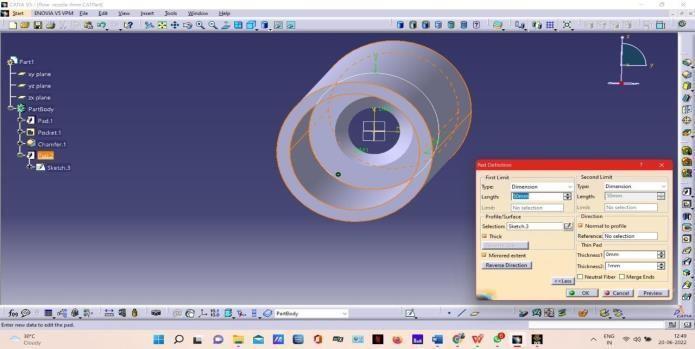

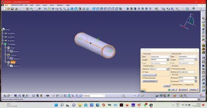
To create orifice plate, go to CATIA and open it. Now startandselectmechanicaldesign,partdesignthenwe willenterintopartdesignmodule.inpartdesignselect sketcherandselectsuitableplane.
Selectcircleandspecifythediameter.Thenclickon exist in workbench. Then we will return to part designmodule.
In part module, select the pad command and specify the length. Then go to sketch module and select circle with required diameter. Click on exist in workbench.
Nowselectthepocketcommand,specifydepthand clickonok.Nowinsketchermodule,selectthepad command and specify the length , thickness then clickonok.Nowwewillobtainorificeplate.
4.2 Modelling of Flow Nozzle in CatiaV5
To create Flow Nozzle, go to CATIA and open it. Now start and select mechanical design, partdesign thenwe willenterintopartdesignmodule.inpartdesignselect sketcherandselectsuitableplane.
Select circle and specify the diameter. Then click on exist in workbench. Then we will return to part designmodule.
Inpartmodule,selectthepadcommandandspecifythe length. Then go to sketch module and select circle withrequireddiameter.Clickonexistinworkbench.
Andselectthepocketcommand,specifythedepthand click on ok. Now select the chamfer and specify the length, angle, and give propagation and then click on ok.
In sketch module, select the pad command and specifylength,thickness,thenclickonok.Nowwewill obtainthefinalflownozzle.
Fig,3:Orificeplateβ=0.2
Fig.5:FlowNozzleβ=0.2
Fig.4:Orificeplateβ=0.4
Fig.6:FlowNozzleβ=0.4
Volume: 09 Issue: 07 | July 2022 www.irjet.net p-ISSN: 2395-0072

5. ANALYSIS OF ORIFICE PLATE AND FLOW NOZZLE
ANSYS develops and markets engineering simulation software program to be used throughout the product existencecycle.AnsysMechanicalfiniteelementanalysis software is used to simulate laptop models of systems, electronics, or system components for evaluation the energy, durability, elasticity, temperature distribution, electromagnetism,fluidglide,anddifferentattributes.

In ANSYS, the fundamentals of FEA concepts, modelling and the analysing of engineering trouble the usage of ANSYS workbench. Computational Fluid Dynamics (CDF) is the evaluation of fluid flows the usage of numericalanswermethodsandinformationstructureto investigate and clear up troubles that involved in fluid flows. The orifice plate and flow nozzle is subjected to Ansysfluentandtheresultedpace,stressarestudiedand calculated coefficient of discharge for specialdiameters. TheclothselectedforreadingisAluminumandfluidused isair.
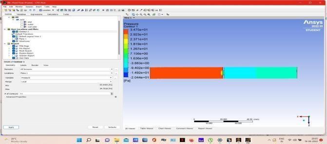
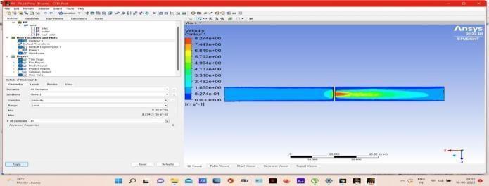
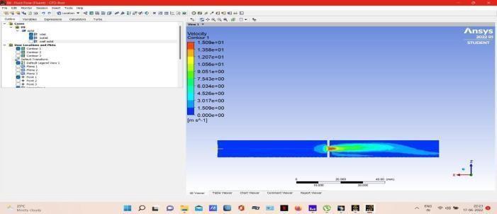
Fig.8:velocitycontourβ=0.2
Fig. 7: Modelsetup
6. RESULTS AND DISCUSSION
Aftertheanalysisisfinishedthenextimportantstepisto understandtheevaluatedresults.Inthisproject,wehad evaluatedvelocity,pressure,coefficientofdischargesofar.
6.1 Orifice plate
6.1.1 Velocity
Select velocity under the solution node in the tree outline,thevelocityofmodelisdisplayedinthegraphics screen.Also,thecorrespondinglegendisdisplayedinthe graphicsscreen.
Fig.9:velocitycontourβ=0.4
Thelegendshavecolorsarrangedinabandfrompinnacle to bottom. Depending upon the type of analysis and parameters evaluated, each color will suggest a extraordinary value. From the abovefigures 8 and nine it'smilesobservedthat,theminimalvelocityislocatedat place wherein waft processes the orifice and the maximumvelocitycomesoutasjettheplatehollowand reaches the downstream. The point at which pace is the maximum is called vena settlement. The blue shade within the version represents the bottom cost of the speed,whilethepinkcolor denotes the maximum fee of thespeed.
6.1.2 Pressure
Select pressure under the solution node in the tree outline, the pressure of model is displayed in the graphics screen. Also, the corresponding legend is displayedinthegraphicsscreen.
Fig.10:Pressurecontourβ=0.2
Fig.11:Pressurecontourβ=0.4
From the above figures 10, 11 it is observed that, the maximum pressure is observed at the flow approaches theorificeandminimumpressurecomesoutfromtheplate holeanditsreachesthedownstream.Theredcolourinthe model represents the maximum value of the pressure, whereasthe blue colour denotes the minimum value of pressure.
Formulas;
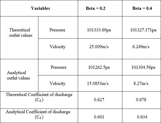
Diameteroforifice d=2mmDiameterofpipe D=10mm Betaratio β=d/D P1V1=P2V2,A1V1=A2V2 QTH Cd =


Theabovetable-1,summarizestheresultsforcoefficient of discharge of each orifice size. It is evident from the above table that increasing the orifice diameter will increase the coefficient of discharge. Furthermore, the values of theoretical coefficient of discharge have less deviation from the Analytical values of coefficient of discharge.
6.2 Flow Nozzle
6.2.1 Velocity
Select velocity under the solution node in the tree outline, the velocity of model is displayed in the graphics screen. Also, the corresponding legend is displayedinthegraphicsscreen.
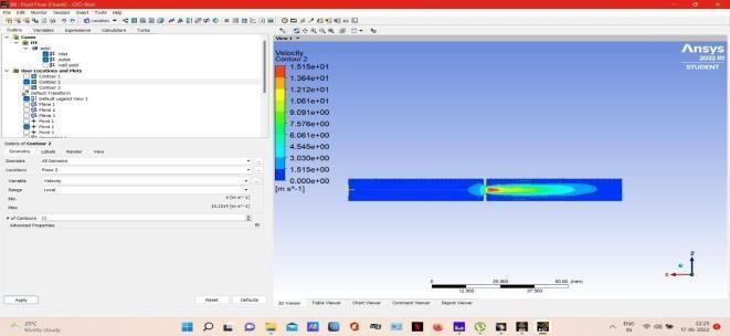
Fig.12:Velocitycontourβ=0.2
Table-1: CalculationsofOrificeplate

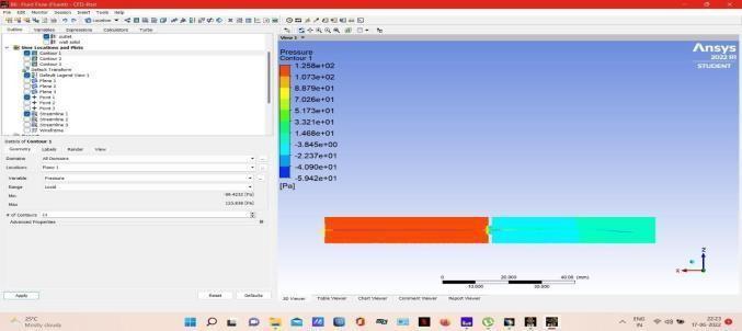
Fig.13:Velocitycontourβ=0.4
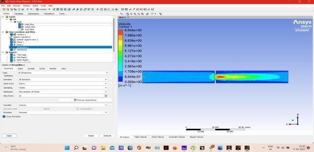
The legends have colours arranged in a band from top to bottom. Depending upon the type of analysis and parameters evaluated,eachcolour will indicatea differentvalue. Fromtheabovefigures12,13itisobserved that, the minimum velocity is observed at the region whereflowapproaches thenozzle, and the maximum velocity comes outasjetfromthenozzleandreachesthe outlet. The blue colour in the model represents the lowest value of the velocity, whereas the red colour denotesthe maximumvalueofthevelocity.
Volume: 09 Issue: 07 | July 2022 www.irjet.net p-ISSN: 2395-0072
6.2.2 Pressure
Select pressure under the solution node in the tree outline, the pressure of model is displayed in the graphics screen. Also, the corresponding legend is displayedinthegraphicsscreen.
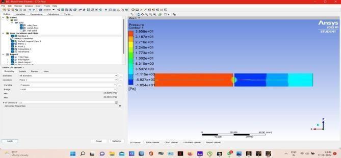

Fig.14:Pressurecontourβ=0.2
From the above figures 14 ,15 it is observed that, the maximumpressureisobservedattheflowapproachesthe flownozzleandminimumpressurecomesoutfromthe nozzle and its reaches the outlet. The red colour in the model represents the maximum value of the pressure, whereasthebluecolourdenotestheminimumvalueof pressure.
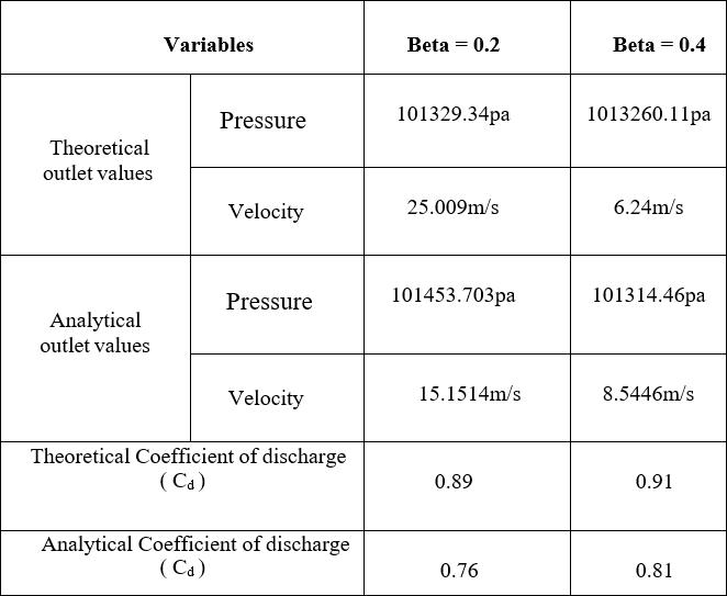
Table-2: CalculationsofFlowNozzle

From the above table-2 summarizes the results for coefficientofdischargeofeachnozzlesize.Itisevidentfrom theabovetablethatincreasingthenozzlediameterwill increase the coefficient of discharge. Furthermore, the values of theoretical coefficient of discharge have less deviation from the Analytical values of coefficient of discharge.Ascomparedtotheorificeplatetheflownozzle ashighcoefficientofdischarge.
7. CONCLUSION
Theconclusionoftheworkisthatbyanalysisandstudying thevelocity,pressure,andcoefficientofdischargeoforifice plateandflownozzleofdifferentdiameters.Itisobserved that the velocity is maximum at downstream than the upstreamoftheOrificeplateandFlownozzle,thepointat whichvelocityismaximumisknownasvenacontracta. Pressureismaximumattheinletandminimumattheoutlet oftheorificeplateandflownozzle.Whenthediameterof the Orifice and Flow nozzle increases, the velocity, pressure decreases and the coefficient of discharge increases. It is observed that the values of theoretical coefficientofdischargehavelessdeviationfromthevalues of analytical coefficient of discharge. The coefficient of dischargeofflownozzleishigherthantheorificeplateby theoreticallyandanalytically.
REFERENCES
[1] SaeidMokhatab,JohnY.Mak,inHandbookofNatural Gas Transmission and Processing (Fourth Edition), 2019.
[2] R.Sangani,D.C.Jayani,A.H.Hingu,M.Y.Jadav,D.V. Jiyavia “Comparison of Experimental, Theoretical and Simulation result for Pressure Drop-in SharpEdged Orifice meter”. International Journal of Science, Engineering and Technology Research(IJSETR), Volume5,Issue3,March2016.

International Research Journal of Engineering
and
Technology (IRJET) e ISSN: 2395 0056

Volume: 09 Issue: 07 | July 2022 www.irjet.net p-ISSN: 2395-0072
[3] Haikrishna V. Gohil, Mohammad AzimAijaz “Finite Element Analysis of Pressure Drop in Orifice Meter””. International Journal of Science, Engineering and Technology Research (IJSETR), ISSN: 2278 0181, Volume3,Issue3,March 2014.
[4] https://sagemetering.com/natural gas flow measurement/orifice platepart vii naturalgas flow meter types/
[5] https://physics.stackexchange.com/questions/405977/ relationshipbetween velocity and pressureof afluid in motion
[6] https://www.nandantechnicals.com/2021/05/flow nozzle introduction working.html
[7] http://www.newpages2u.com/userfiles/19646/attach ment/2844641/20200116_05af882da13137a3c9733b6 e3fba508c/Flow Nozzles.pdf
[8] https://webdev3.coasthotels.com/cfd modelling of hydrodynamics and heat transfer in pdf/
