International Research Journal of Engineering and Technology (IRJET) e ISSN: 2395 0056

Volume: 09 Issue: 07 | July 2022 www.irjet.net p ISSN: 2395 0072

International Research Journal of Engineering and Technology (IRJET) e ISSN: 2395 0056

Volume: 09 Issue: 07 | July 2022 www.irjet.net p ISSN: 2395 0072
1,2 Student, Dept. of Civil Engineering, Mahavir Swami College of Engineering & Technology, Surat, Gujarat 3 Professor, Dept. of Civil Engineering, Mahavir Swami College of Engineering & Technology, Surat, Gujarat. India ***
Abstract - The design communication is gradually being changed from 2D based to integrated 3D digital interface. Building Information Modeling (BIM) is a model based design concept, in which buildings will be built virtually before they get built out in the field, where data models organized for complete integration of all relevant factors in the building lifecycle which also manages the information exchange between the AEC (Architects, Engineers, Contractors) professionals, to strengthen the interaction between the design team. BIM is a shared knowledge about the information for decisions making during its lifecycle. There’s still much to be learned about the opportunities and implications of this tool. In this paper we have shown the comparison and work done on both software named AutoCADandRevit.
Key Words: AutoCAD, Revit, Drafting, Modelling
AutoCAD is used by AEC (Architecture, Engineer, and Construction) to generate and optimize 2D and 3D designs. AutoCAD is a Computer Aided Design (CAD) drafting software, marketed by Autodesk. On the other hand, Revit is powerful tool for everyone in construction industry to make 3D Parametric Drawings with single databaseforeveryelementinvolvedindesign.
The major dividing factor for both software is theyare both work as different bases which is CAD and BIM respectively for AutoCAD and Revit. CAD is Computer Aided Design. CAD software provides technology for architects, engineers, and construction professionals to design and create precise 2D and 3D drawings, replacing manualdraftingwithanautomatedprocess.BesidesBIMis Building Information Modeling. It is an intelligent 3D model based process that gives architecture, engineering, andconstruction(AEC) professionals the insightand tools toefficientlyplan,design,construct,andmanagebuildings andinfrastructure.
The biggest difference is that AutoCAD is a CAD software and Revit is software forBIM. While AutoCAD is a general drawing tool with broad application, Revit is a design and documentation solution, supporting all phases and disciplinesinvolvedinabuildingproject.
Revitisused tocoordinateall data inputs(including CAD) andproducefederatedprojectdeliverables.Bothprograms are often used within the same firm, with BIM and CAD specialistsworkingondifferentelementsofaproject.
AutoCAD is globally used by surveyors, designers, engineers, drafters. Globally, AutoCAD has proven as an efficient and user friendly program. AutoCAD software is recognized internationally for its remarkable editing capabilities,whichmakeitlikelytodigitallydrawbuilding plansorrecreate3Dimages.Thissoftwarewasdeveloped in the year 1982 by Autodesk. AutoCAD consist of some Drawing Commands such as Line, Polyline, Circle, Rectangle,Eclipse,Arc,Hatch,Constructionline,etc.There aresomeModificationtoolsavailabletomodifyinexisting drawing such as Extended, Trim, Offset, Mirror, move, Copy,Scale,Fillet,Rotate,Erase,Align,Break,etc.
AutoCADcanbedefinedastheuseofcomputersystemsto assist in the creation, modification, optimization of a design. In this, we can create both 2D and 3D drawings usedinconstructionandmanufacturing.Itwasdeveloped by John Walker in 1982 with the help of AUTODESK and maintained it successfully. It is most commonly used for creating and modifying 2D & 3D designs for professional drafting with detail measurement information about the conceptualdesignandlayoutoftheproduct,alsoavailable in 14 different languages with respect to location. Users can customize the CAD software with available add on apps as per project requirements. User specialized tool setting can be done to view and design product in wireframe and surface modelling. Widely preferred in the industries of mechanical, telecom, civil, architectural engineering. It stands on demand to students and industriesbecauseofitsrequirements
Unit (UN): It can be used for controls coordinate and angledisplayformatsandprecision. Line (L): It can be used for making simple lines in the drawing.
International Research Journal of Engineering and Technology (IRJET) e ISSN: 2395 0056

Volume: 09 Issue: 07 | July 2022 www.irjet.net p ISSN: 2395 0072
Circle (C): It is the command used for making a circle in AutoCAD.
Polyline (PL): This command can be used to make a Polylineinyourdrawing.
Rectangle (REC):Thiscommand will makea rectangle in AutoCAD.
Arc (ARC): As the name suggests, this command can be usedtomakeanarcinAutoCAD.
Ellipse (EL): As the name suggests, this command can be usedtomakeanellipsewiththemajorandminoraxis.
Copy (CO): This command is used to copy object(s) in AutoCAD.
Trim (TR): This command is used for trimming a geometry.
Scale (SC):Thiscommandisusedtochangethescaleofan object.
Block (B):Thiscommandisusedforcreatinga block;the properties of the block can be defined using the block definitionwindow.
Insert (I):Thiscommandcanbeusedtoinsertanexisting blockoradrawingasablockinAutoCAD.
Test style (ST): Using this command you can open text style window which controls properties of the default AutoCADtextstyle.
Explode (X): This command can be used to explode objectslikePolylinetosimplelines,anarrayora block to asimplegeometryetc.
Fillet (F): This command can be used to add rounded corners to the sharp edges of the geometry; these round cornersarealsocalledfillets.
Layer (LA): This command can be used to open layer propertiesmanagepalettewhichisatoolforcreatingand managinglayersinadrawing.
Revit is a 3D parametric modelling software package for building information modelling (BIM). Parametric modellingmeansyoucancreateeachofthefollowingfrom within the tool, providing a single database for all the elementsinvolvedinyourdesign:
Instead of drawings, making a design more precise. Furthermore, it can help you generate floor plans, elevations,sections,details,andschedules.BeforetheBIM methodology was introduced, these tasks were both complex and time consuming. Nowadays, thanks to BIM software such as Revit, the design process has become morestraightforwardandefficient.
The scope of the study is to explore and evaluate the advantages of integration which will enables theeaseofproject.
It is viable career option as implementation of softwareisdoneforbetterdevelopment.
BIM digitalizes the life of building which gives solutiontoeveryphaseofstructure.
BIM increases productivity, infrastructure value andquality
Reductionofcostandtime
Revitiscommercial buildinginformation modelling (BIM) software by the companyAutodesk. It’s generally used by architects,structuralengineers,mechanical,electrical,and plumbing (MEP) engineers, designers, and contractors. AutodeskRevitallowsuserstocreate,edit,andreview3D models in exceptional detail. Revit allows you to place real lifebuildingcomponentssuchaswindows,walls,and doors
Drawingroom
Drawingroom
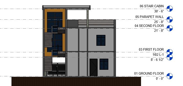
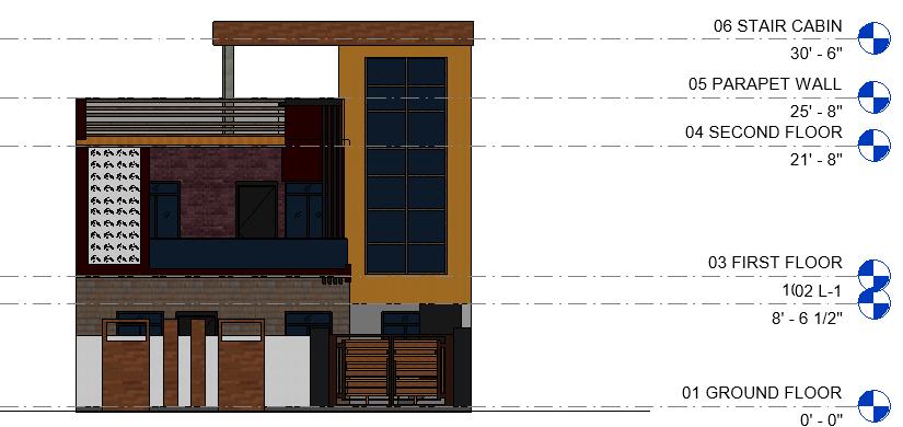
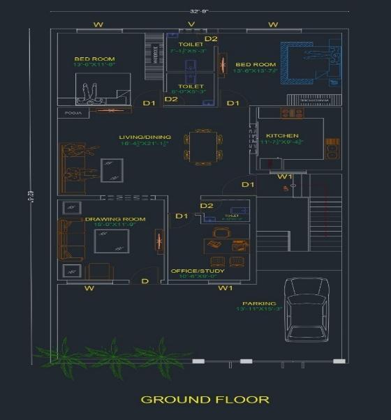

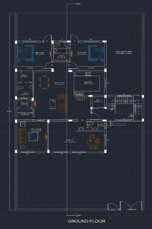
Groundfloor
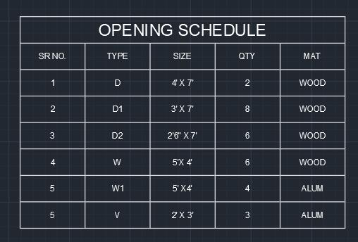
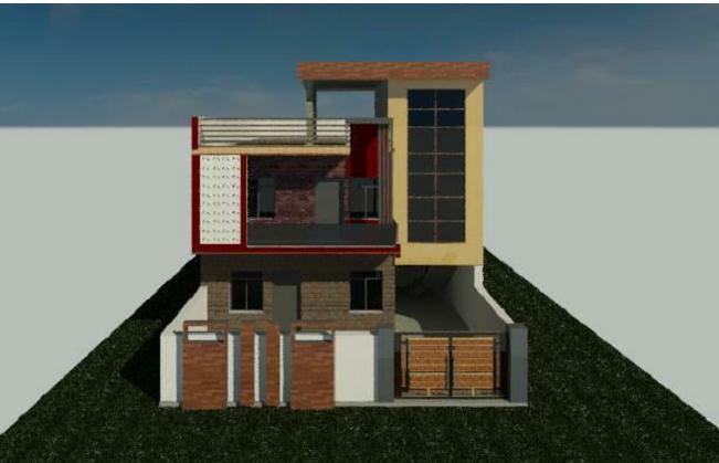
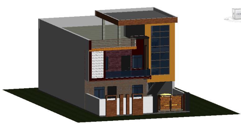

Drawingroom
Leavingroom
Dressingroom
Parkingarea
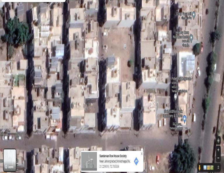
AttachedbathandaToilet
02CommonbathandaToilet
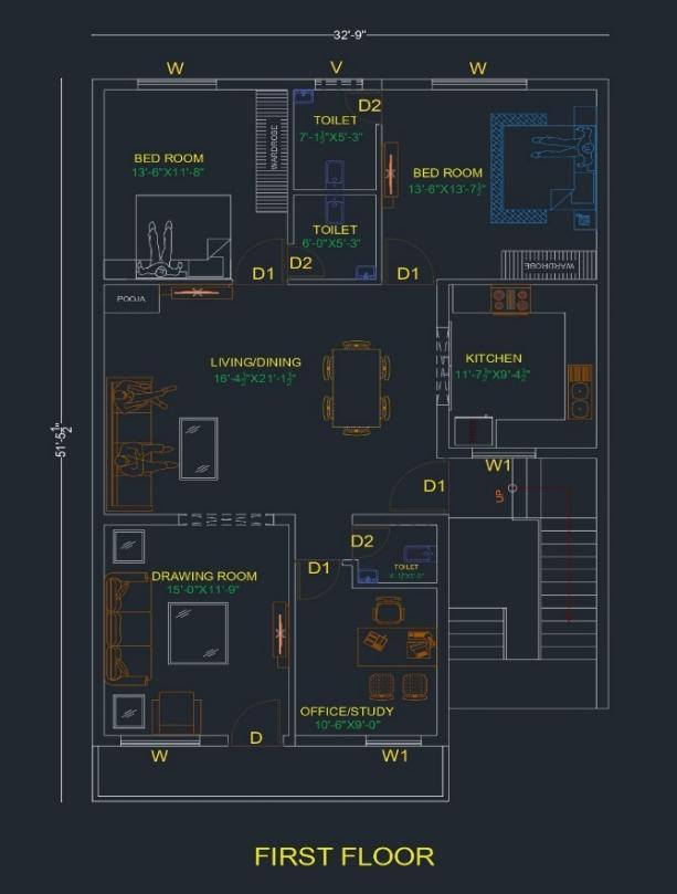
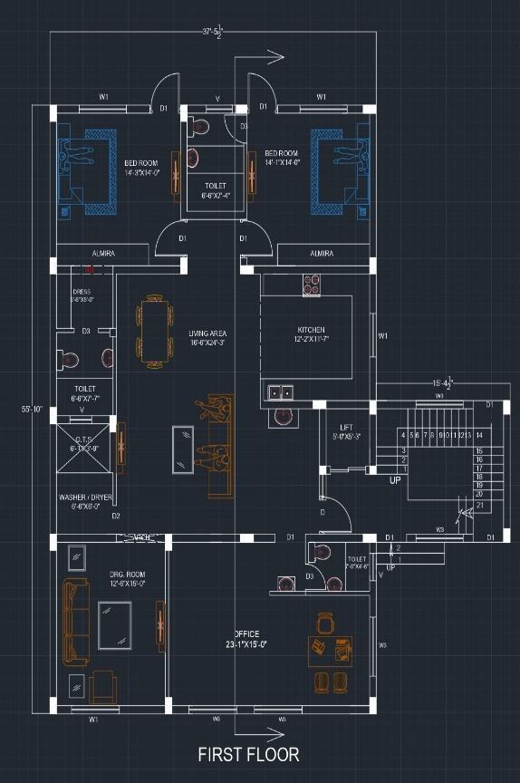
Firstfloor
Drawingroom
Leavingroom
Dressingroom
AttachedbathandaToilet
02CommonbathandaToilet
International Research Journal of Engineering and Technology (IRJET) e ISSN: 2395 0056

International Research Journal of Engineering and Technology (IRJET) e ISSN: 2395 0056

Volume: 09 Issue: 07 | July 2022 www.irjet.net p ISSN: 2395 0072
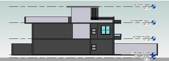
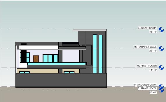
resultsofsystem’sintegration.TheAimofthisresearchis to set side by side Revit and AutoCAD for interior design andArchitecturepurposes.
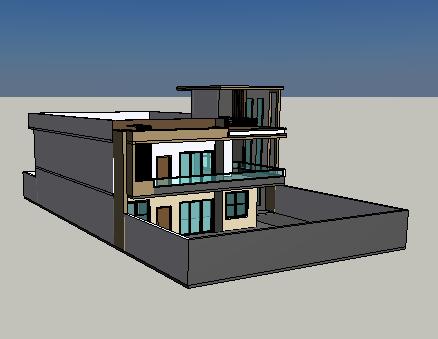
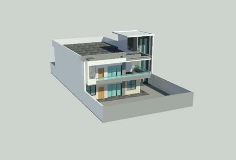
The primary goal of the project has been met, which is to gain knowledge in planning, modelling and analysis using software’s. Getting familiar with structural software like AutoCAD and Revit. A clear design and modelling of residential building with architectural plans. All the draftingwasdonebyusingAutoCAD.Alsothesedrawings madeonAutoCADalsoservedasabasefortransferofthe structure for modelling and analysis into Revit. The modeling of the building in Revit software gives a beautiful,realistic3Dviewofthebuilding.
[1] Bergin, Michael S. "A Brief History of AUTOCAD AND REVIT". Archived from the original on March 2, 2014. RetrievedDecember15,2012
[2] J. Vinoth Kumar* and Mahua Mukherjee 2009, consulting Scope of Building Information Modeling (AUTOCAD AND REVIT) in India, Department of ArchitectureandPlanning,IndianInstituteof Technology, Roorkee,India.
[3] Allen Consulting (2010), Productivity in The Buildings Network: Assessing the Impacts of Building Information Models, Report to the Built Environment Innovation and IndustryCouncil,Sydney,October.
[4] Mehmet F. Hergunsel 2011, consulting Benefits of AUTOCAD AND REVIT for Construction Managers &AUTOCAD AND REVIT base schedule, Degree of Master ofScienceinCivilEngineering.
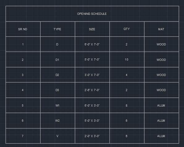
Revitisveryhandytooltowhichprovidesconsistencyand helpstocoordinate whileworkingonanydrawing/model in design Phase. Revit is not only a tool which is used for Drafting purposes but also it is afflicted in analysis of Drawing. We do have used both Revit and AutoCAD to make construction documents, where differences and spaceofworkisquitenotablydifferboth.InAutoCADyou candrawyourimagination, simplyAutoCADisdrawlines which we used to make by hand but digitally, whereas in Revit you does need decent Library and Family to start and make model. In simple words, in AutoCAD you can draw whatever you want and it gives you the results and per your drawings. In the other hand, Revit needs quite a bitknowledgeofConstructionaswellasitrequiresuserto have higher understanding of the way it works. By these, we can say Revit is not preferable for Design phase of Drawing, but for testament it put forward incredible
[5]Crotty,Ray(2012).TheImpactofBuildingInformation Modelling: Transforming Construction. London: SPON/Routledge.p.72.ISBN9781136860560.
[6]MichaelGraves(September1,2012)."Architecture and the Lost Art of Drawing". The New York Times. AutoCAD andRevit.viainterconnecteddatabases.
[7] Building planning and drawing DR.N. Kumara Swamy, M.E., B.E. (civil engineering), Principal. Sixth edition:2012,CHAROTARPUBLICATIONS.
[8] Autodesk to Acquire Revit Technology Corporation, 2002AutodeskPressRelease.
[9] R. D. Deshpande, Manoj N. Pai, N. Pawan, Aashish P. Pednekar, Design and Estimation of Basement (g+1) Residential Building, International Research Journal of
International Research Journal of Engineering and Technology (IRJET) e ISSN: 2395 0056

EngineeringandTechnology(IRJET),Volume:04Issue:06 |June 2017.
[10]PunamBhimraoKokate,MilindsInternationalJournal of Innovative Science and Research Technology, Volume/Issue:Volume3 2018,Issue4 April
Mr. Dhruv Patel
Studying Final Year of B.E Civil at MahavirSwamiCollegeofEngineering &Technology,Surat,Gujarat.
Mr. Dhaval Patel
Studying Final Year of B.E Civil at MahavirSwamiCollegeofEngineering &Technology,Surat,Gujarat.
Prof. Janki Patel
ProfessoratMahavirSwamiCollegeof Engineering & Technology, Surat. B.E Civil.Surat,Gujarat.
Volume: 09 Issue: 07 | July 2022 www.irjet.net p ISSN: 2395 0072 © 2022, IRJET | Impact Factor value: 7.529 | ISO 9001:2008 Certified Journal |