International Research Journal of Engineering and Technology (IRJET) e ISSN: 2395 0056

Volume: 09 Issue: 07 | July 2022 www.irjet.net p ISSN: 2395 0072

International Research Journal of Engineering and Technology (IRJET) e ISSN: 2395 0056
Volume: 09 Issue: 07 | July 2022 www.irjet.net p ISSN: 2395 0072
1Student, Department of Mechanical Engineering, Sardar Patel College of Engineering, Andheri, Maharashtra, India
2Head of Department, Department of Mechanical Engineering, Sardar Patel College of Engineering, Andheri, Maharashtra, India ***
Abstract The strength of a vehicle is one of the most significant factors that contribute to determining its crashworthiness during an impact. During the designing process, it is essential to ensure that the structure of a car can protectorreducethelevelof damagedonetothedriverorthe car’s body by absorbing the impacted load and reducing the stress values. It has been scientifically proven that the frontal side of a car is more prone to high energy impacts and deformation during a crash. A frontal accident using an explicit dynamics code is simulated and analyzed here using the ANSYS Workbench to calculate the effect of the frontal collision on various barriers. The developed stress and deformation on impact with a static concrete wall and a moving car with its speed of 20 m/s and its body structure were investigated using a car body made of aluminium, stainless steel, and composites travelling at an initial velocity of 30 m/s. The developed stress was plotted and analyzed for all three scenarios, the developed stress, and deformation resultingfromthecrash.Thedeformationcausedbyacollision between two moving cars was found to be the greatest, whereas that caused by static walls was the least adverse.
Key Words: Crashworthiness, Explicit Dynamics, ANSYS, Frontal CollisionThe crashworthiness of a car determines its structural integrity. The increasing importance of the safety of a passengercarhasbecomearelevantfieldofstudyinterms ofpassengersafety,frameanalysis,andmaterialselection. With the advent of Material Sciences and Composites, selecting an appropriate material has become difficult. Composites offer higher structural strength without increasing weight. The possibilities in terms of use in the automobileindustrythuswidenandopenabroaderscopeof the analysis. Over the years, various studies have been conductedonthestrengthofframeormaterialanalysisin different passenger car components. Studies have been mutuallyexclusiveandareyettoofferaconclusivematerial forbroaderapplicationincarframesandimprovementofits strength.Anotherreasonfortheimprovementinstructural strength is the safety of the driver and pedestrian. This factor makes suitable simulations essential for better analysesoftheselectedmaterial.
In2015,itwasreportedthatcaroccupantwasthehighest single casualty group in Europe, with 45% of death [3]. Frontalimpactcollisionsinvolvingcarsarethesinglemost frequent accident category resulting in a high fatality and severeinjuriestotheoccupants.Criticalfatalinjurypoints associatedwithfrontalimpactarethehead,followedbythe chest, and then the abdomen, while those resulting in disabilityaremostlythoseinthelegsandneck.Thecritical determinants of injury and its severity are travel speed, restraint use, interior occupant contact, size and weight mismatch of involved vehicles, ejection from the car, and inadequatevehiclecrashprotection[4].
Severalvehicledesigntechnologieshavebeenimprovedto assistthedriverinavoidingaccidentoccurrences.Evenifthe accidentoccurs,thevehicleshouldprotectbothpassers by and the occupants against serious injuries. Therefore, researchers and industries are exploring all the possible optionstoenhancevehiclecrashprotectivedesign[5].The industriesandgovernmentarestrivingtowardsproducing environmentally friendly, improved, lighter cars while maintaining the rider’s safety [6]. Recently, car manufacturershaveusedlightweightcompositeAluminium, magnesium,plastics,orothersteelmaterialsofhighstrength toconstructcarsduetotheirstrengthandtensileproperties [7],[1].
Aluminiummaterial mightnotbedurableinthecarbody. Still its lightweight increases the rate of acceleration and provides better fuel mileage needed for the efficient operation of Hybrid Electric Vehicles (HEVs) and pure Electric Vehicles (EVs). An essential requirement in the designprocessofanautomobilecompanyisthedeformation zones which are meant to protect the car occupants. Its primary function is to absorb the impact through deformation while preserving the space occupied by the crew.Acarcrashtestisoneofthemostimportanttestsused tovalidatethedeformation designstrengthofthevehicle. Thepopularlyknowncrashtestsincludefront,frontoffset, side,androllovercrashtests[6].Inadditiontothecostof running a physical test, the time needed to carry out an experimentalcrashtestisrelativelyhighaswellasthedata used might be incorrect. As a result, simulation is used to eradicatesuchproblemsusingnumericalmodellingmethods suchastheFiniteElementMethod(FEM).
International Research Journal of Engineering and Technology (IRJET) e ISSN: 2395 0056
Volume: 09 Issue: 07 | July 2022 www.irjet.net p ISSN: 2395 0072
AstudypresentedbyA.K.Pickettaetal.[8],foundthatthere isarapidincreaseinmorecompetitivemoderncardesigns. Also, there is a need for an improved bumper system mechanism that will solve crashing problems while maintaininglowcostatoptimalperformance.Itisnecessary toincreasetheperformanceofcarsintermsofcrashes.The factors that must be improved include materials used and energy absorbers. The energy should be absorbed or transmittedbythepartsorcomponentsthataresubjectedto impactduringacrash.However,thispowerintakeabilityof the car body is determined by its geometrical design and materials used [1]. A car should be able to resist impact during crashing, thereby keeping both the driver and the occupant safe from having any injury. This withstanding propertyisknownascrashworthiness[7].
In a paper by Sadhasivam et al. [9], vibration and crash analysisduringafrontal,side,andrearcollisionimpactofa car body was investigated through simulation. The paper determines the natural frequency of the structure within whichthesafetyofthecaroccupantsisguaranteed.Ifthetest fails, the analysis has to be repeated using different body materials,andsometimesthestructurehastobere designed and adjusted until the safety standard is achieved and guaranteed [2]. An investigation on the safety of a car passenger at reduced cost wasconducted by Byeong et al. [10]. An electric vehicle was used in LS DYNA to perform frontalcrashanalysisoftheupperandsubframebodyofthe car.Twocrashanalyses:ahigh speedvehicleintoawalland ahigh speedvehicleintoastationaryvehicle,weresimulated and presented by Lin et al. [11]. The analysis was done to determinewhichimpactwouldharmthedriverandbeable todesignabumpermodelcapableofwithstandingthecrash impact. Tejasagar et al. [12] performed frontal car crash analysis using computer simulations intending to reduce productiontesttimeandcost.Frontalandsidecollisioncar crash analysis in a transient dynamic was performed by Praveenetal.[13].Thedeformationsandstressesobtained from the collisions were used to determine the car’s crashworthiness.Theresponsesofadummydriverinafour seatmodelledcartofrontalandsidecrashingwereselected andpresentedbySaeedetal.[14].
AnSUVcarwasusedasthehittingvehiclewhilethedesigned variableswereevaluatedandgenerated.Thispaperpresents acrashanalysisofa3Dmodelledcarbodyperformedusing the ANSYS workbench. In line with the quest for a lighter bodyforEVsandHEVs,thisstudyusesAluminiummaterial whichisrelativelynewinautomanufacturingindustries.An explicitdynamicanalysisofthecarbodyataspeedof35m/s and on collision impact for three different scenarios was conducted.Thestudyaimstoinvestigatethecrashworthiness ofthecarbodybasedonitsmaterialandstructuraldesignby measuringtheamountofdeformationandstressexertedon
thefrontalimpactofthecarbodyonasteelwall,astaticand ahighspeedmovingcar.
Abolfazi Masoumi et al. [16], tested Material selection for automotive closures. The conclusion states that safety is influenced by different factors such as cost, weight, and structural performance. The paper offered an detailed analysisofthedistancebetweenenginepartsandthefront bumper,whichisessentialforheadimpactandhighlightsthe importance of material selection. N. Bhaskar et al. [17] conductedasimilaranalysisforthedesignofacarbonnet. ThematerialselectedwasAluminiumAlloy,awidelyapplied metalintheautomotiveindustry.
J. Schulzetal. [18]incorporatedcompositematerial incar bonnets.Thecriteriabehindchoosingcompositematerials werestiffnessandpedestriansafety.Energyabsorptionon frontal collision was also considered to select a suitable material.Thecarbonnetsandwichdesignwasthemainfocus inculcatingacoredesign.Thematerialofthecoreimparted morestrengthtothebonnetinadditiontotheouterfabric. ThecompositesusedwereCarbonFiberReinforcedPlastic (CFRP)withPolyvinylChlorideasasuitableresin.
Furtheranalysistoreinforcethethemeofthisresearchwas done by Narayana et al. [19], which further solidified the introductionofcompositesinCarBonnet.MartinMohlinetal. [20],JohanKarlsson[21],andL.Kiranetal.[22]conducted weightreductionanalysesbyintroducingmaterials.
Thelatestadvancementinhybridandpureelectric
hasatrade upbetweenmileageandweight,requiringlighter bodyweight.Coupledwiththat,thesurgeinpopulationand rapidinfrastructuraldevelopmentsofhigh speedroadsand multiplelineshasaggravatedtheneedforthecriticalsafety assessmentofthevehiclesproduced.
International Research Journal of Engineering and Technology (IRJET) e ISSN: 2395 0056
Tensile Yield Strength Pa 2.8e+008 TensileUltimateStrengthPa 3.1e+008
ThepropertiesofthestainlesssteelareshowninTable2.
Density 7750kgm^ 3
CoefficientofThermal Expansion 1.7e 005C^ 1
SpecificHeat 480Jkg^ 1C^ 1 ThermalConductivity 15.1Wm^ 1C^ 1
Resistivity 7.7e 007 ohmm CompressiveUltimate StrengthPa 0 CompressiveYieldStrength Pa 2.07e+008
TensileYieldStrengthPa 2.07e+008 TensileUltimateStrengthPa 5.86e+008
ThepropertiesofthecompositeareshowninTable3.
Density
1857kgm^ 3
TensileYieldStrength 4.401e+008Pa TensileUltimateStrength 4.401e+008Pa
IsotropicSecantCoefficient ofThermalExpansion 1.688e 005C^ 1 IsotropicThermal Conductivity 0.5523Wm^ 1C^ 1
SpecificHeatConstant Pressure 1069 kg^ 1C^ 1
Theconcretepropertiesassignedtothewallareshownin Table4.
Density 2392kgm^ 3
TensileYieldStrength 1.095e+006Pa TensileUltimateStrength 1.196e+006Pa
IsotropicSecantCoefficientof ThermalExpansion 1.015e 005C^ 1 IsotropicThermal Conductivity 2.933Wm^ 1C^ 1
SpecificHeatConstant Pressure 936.3Jkg^ 1C^ 1
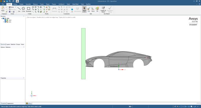
For this study, SOLIDWORKS and ANSYS were used for designandsimulation,materialswereaddedtotheANSYS directory,andtheModalSettingsforExplicitDynamicswere specified.ThefinalreportwasgeneratedfromANSYS,which containedtherequirednumericalvaluesandgraphsforeach of the tested parameter. These values and graphs were inferred,andtheconsolidateddataispresentedinthisstudy. Below mentioned are the units that are taken into considerationfortheexperiment.
UnitSystem
Metric (m, kg, N, s, V, A) Degreesrad/sCelsius
Angle Degrees RotationalVelocity rad/s Temperature Celsius
ANSYS Explicit Dynamics was used for this study. The EngineeringData wasupdated.Concrete(non linear)was chosen as additional material. Aluminium, Stainless steel, and Composite was added to the material library, and the following properties for the same were input for each material:Density,IsotropicElasticity(Young’sModulusand Poisson’s Ratio), Bilinear Isotropic Hardening (Yield StrengthandTangentModulus),andSpecificHeat.
ThegeometrywasimportedintoANSYSandtheModelwas opened.Geometrysettingswereupdated.Concretematerial was assigned to the wall, and the stiffness behaviour was
Volume: 09 Issue: 07 | July 2022 www.irjet.net p ISSN: 2395 0072 © 2022, IRJET | Impact Factor value: 7.529 | ISO 9001:2008 Certified Journal | Page2591
International Research Journal of Engineering and Technology (IRJET) e ISSN: 2395 0056
Volume: 09 Issue: 07 | July 2022 www.irjet.net p ISSN: 2395 0072
changed from the default ‘flexible’ to ‘rigid’. Different materialswereassignedtothecar,andathicknessof10mm was given to the car body. Table 5 mentions the initial conditionsallottedtotheparts.
Pre StressEnvironment NoneAvailable
PressureInitialization FromDeformedState InputType Velocity
DefineBy Components
CoordinateSystem GlobalCoordinateSystem
XComponent 30.m/s
YComponent 0.m/s
ZComponent 0.m/s Geometry Car
Meshinginvolvesdividingtheentiremodelintosmallpieces (elements). The element type is decided first to mesh the model.Acoarsemeshwasgeneratedwith10331nodesand 9649elements.VelocitywasaddedintheInitialConditionsof Explicit Dynamics. To justify the suggestion of a material, three different velocities of 30m/s were taken along the negativeX directionsuchthatthecarwouldcollidewiththe wallwiththesevelocities.
Table
Step Controls
NumberOfSteps 1
CurrentStepNumber 1
LoadStepType ExplicitTimeIntegration EndTime 1.e 002
ResumeFromCycle 0
MaximumNumberofCycles 1e+07
MaximumEnergyError 0.1
ReferenceEnergyCycle 0
InitialTimeStep ProgramControlled
MinimumTimeStep ProgramControlled
MaximumTimeStep ProgramControlled
TimeStepSafetyFactor 0.9
CharacteristicDimension Diagonals
AutomaticMassScaling No
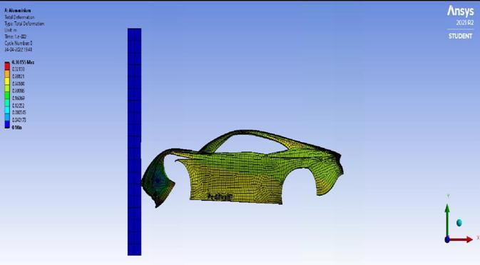
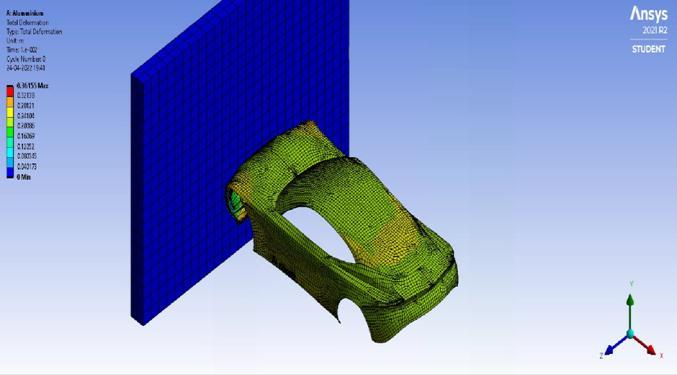
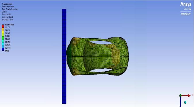
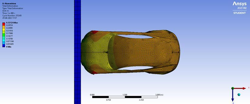
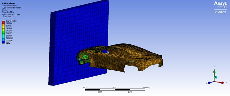
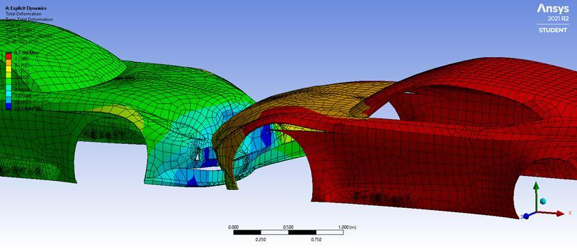
4.1. Aluminium 4.1.1. Aluminium car v/s Concrete wall
Fig 2:Totaldeformationofaluminiumcarbody
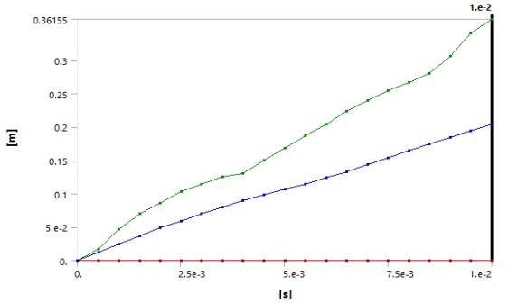
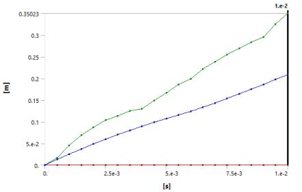
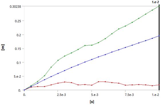
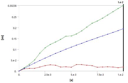
Fig 3:Totaldeformationgraphforaluminiumcarbody
Object Name Total Deformation (m)
Equivalent Elastic Strain (m/m)
Equivalent Stress(Pa)
Minimum 0 3.0782e 005 1.0891e+005
Maximum 0.36155 7.2068e 002 3.7902e+009
Average 0.20467 2.5983e 003 1.4919e+008
2022, IRJET | Impact Factor value: 7.529 | ISO 9001:2008 Certified Journal
International Research Journal of Engineering and Technology (IRJET) e ISSN: 2395 0056
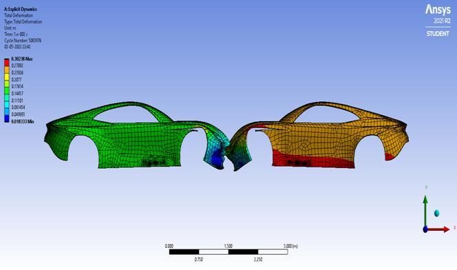
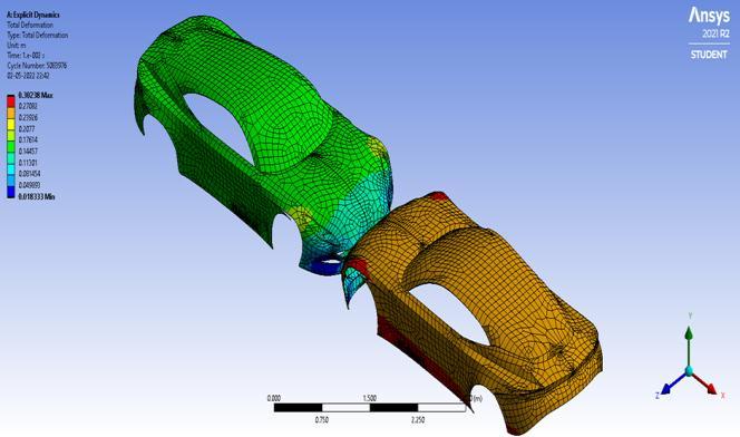
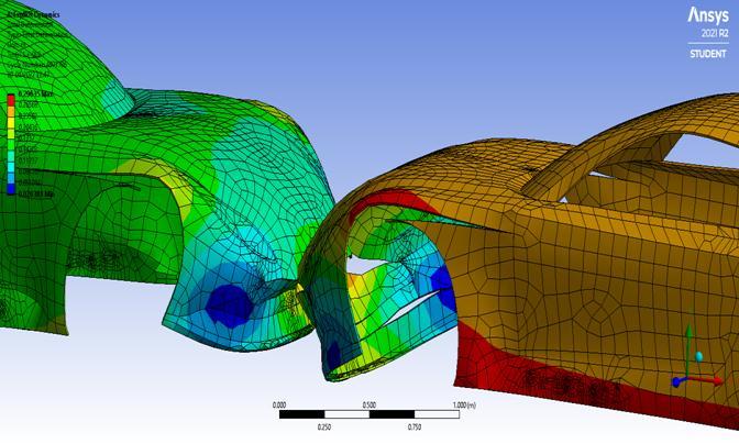
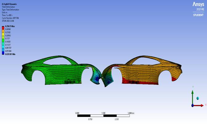
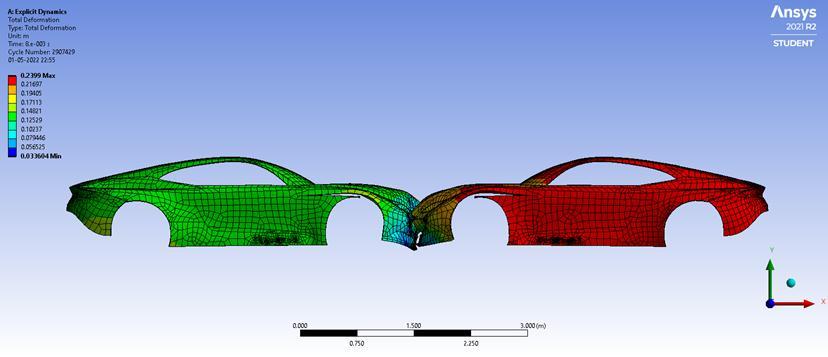
Recentadvancesinhybridandpureelectricvehicleshave created a trade off between mileage and weight, so lightweight body parts are necessary. The increase in population density and the rapid development of transportationinfrastructures,suchashigh speedroadsand multiple lines, have heightened the need for the critical safetyassessmentofvehiclesproduced.Asimplecarbody structurewassimulatedinafrontalcollisionusingANSYS explicitdynamicmethodat30m/s.Threedifferentmaterials wereconsideredforeachcase.Basedontheresults,itcanbe determinedthatamovingcarwillcausemoredamagetothe carbodythanastaticwall.
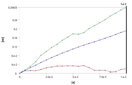
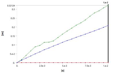
Further, the figures illustrate the degree of deformation experiencedbythevehicleineachcase.Thecollisiontime and deformation are linearly related. The amount of deformation for the dynamic cars is higher, and then the deformationforthewallisnext.Thus,thedesignobtained using aluminium sheets needs to be optimized. It experiences a high amount of stress and deformation, especiallyinacar to carcollision,whichisexpectedtobe themostcommonscenarioforvehicleaccidents.Itisnoted that composite cars are the lightest with 264kg in mass, whereasstainlesssteelcarsaretheheaviestwith1100kgof mass. In spite of its heavy weight, it is seen that stainless steelcarshavethebestreadingstowithstandthecrash,and composites have the most brittle nature. Aluminium can proveagoodmaterialifstrengthisincreasedbyperforming somemechanicalprocesses.Itislighterthanstainlesssteel and more robust than composite material. In order to determinethebestbodystructureandmaterialstousefor the construction of cars, it is recommended in the future study that different car body structures with hybrid aluminiummaterialmixturesbeusedtomodelandanalyze thecrashworthinessofthecarsanddeterminethebestbody structureandmaterialstouse.
WewouldliketoacknowledgeourgratitudetoDr.Balwant Bhasme and Dr. R. S. Maurya for sharing their pearls of wisdomwithuswhilereviewingthisresearch.
WewouldalsoliketothankSPCEInstituteforprovidingus withthesoftwareinthecomputerlab.
[1] LPraveenandNSandeepKumar,"CrashAnalysisofa composite car body," in International Conference on Advancement in Aeromechanical Materials for Manufacturing,India,2018.
International Research Journal of Engineering and Technology (IRJET) e ISSN: 2395 0056
Volume: 09 Issue: 07 | July 2022 www.irjet.net p ISSN: 2395 0072
[2] A.P.Lokhande,A.G.Darekar,S.C.NaikNimbalkar,andA P. Patil, "Crash Analysis of Vehicle," International Research Journal of Engineering and Technology (IRJET),vol.3,no.12,pp.1070 1075,2016.
[3] W. H. Organization, "Global Status on Road Safety Report,"WorldHealthOrganization,Europe,2015.
[4] C.A.Hobbs,PrioritiesforMotorVehicleSafetyDesign, Brussels:EuropeanTransportSafetyCouncil,2001.
[5] V.S.R.Centre,(2011)WrittenevidencetotheUKHouse of Commons Transport Committee, London: LoughboroughUniversity,2011.
[6] B.S.N.Pavan,M.V.Reddy,andK.A.Reddy,"Designand Crash Analysis of Car body using FRP material," International Journal of Research In Advance Engineering Technology, vol. 6, no. 2, pp. 368 381, 2017.
[7] C.S.Kiran,J.Sruthi,andS.C.Balaji,"DesignandCrash AnalysisofaPassengerCarusingANSYSWorkbench," CVRJournalofScienceandTechnology,vol.13,pp.96 100,2017.
[8] A. K. Picketta, T. Pyttelb, F. Payenb, F. Lauroc, N. Petrinicd,H.Wernere,J.Christlein,"Failureprediction for advanced crashworthiness of transportation vehicle," International Journal of Impact Engineering, vol.30,p.853 872.,2004.
[9] C. Sadhasivam, and S. Jayalakshmi, "Simulation of car body bydevelopmentof staticanddynamicanalysis," International Journal of Automobile Engineering ResearchandDevelopment,vol.4,no.3,pp.1 6,2014.
[10]B. S. Kim, K. Park, and Y.Song, "Finite element frontal crash analysis of vehicle’s platform with upper and subframe body," in 28th International Symposium on AutomationandRoboticsinConstruction,Seoul,Korea, 2011.
[11]L.C.S,K.D.Chou,andC.CYu,"Numericalsimulationof vehicle crashes," Applied Mechanics and Materials, p. 135,2014.
[12]T. Ambati, K.V.N.S. Srikanth and P. Veeraraju, "Simulation of vehicular frontal crash test," InternationalJournalofAppliedResearchinMechanical, vol.2,no.1,pp.24 29,2012.
[13] T.A.Babu,D.V.Praveen,andM.Venkateswarao,"Crash analysis of car chassis frame using finite element method,"InternationalJournalofEngineeringResearch &Technology,vol.1,no.8,pp.1 8,2012.
[14] S.Barbat,X.Li,andP.Prasad,"Vehicle to vehiclefront to sidecrashanalysisusingaCAEbasedmethodology,"
Passive Safety Research and Advanced Ford Motor Company,UnitedStates,2007.
[15]A.Muhammad,andI.H.Shanono,"StaticAnalysisand OptimizationofaConnectingRod,"InternationalJournal ofEngineeringTechnologyandSciences,vol.6,no.1,pp. 24 40,2019.
[16]AbolfaziMasoumi,MohammadHasanShojaeefard,Amir Najeebi. (2011). Comparison of steel, aluminum and composite bonnet in terms of pedestrian head impact,SafetyScience,Vol.49,1371 1380.
[17]N.Bhaskar,P.Rayudu.(2015).DesignandAnalysisofa CarBonnet,InternationalJournalofCurrentEngineering andTechnology,Vol.5,3105 3109.
[18]Vulavapoodi Narayana, L. Ramesh, K. Veeranjaneyulu.(2016). Design and Analysis of Car Bonnet by Using PRO E Abs Ansys with FRP, International Journal & Magazine of Engineering, Technology,ManagementAndResearch,Vol.3,811 821.
[19]MartinMohlinandMikaelHanneberg.(2016).Chassis Component Made of Composite Material, M.S. Thesis, KTHRoyalInstituteofTech.,Stockholm,Sweden,78.
[20]JohanKarlsson.(2016).CompositeMaterialinCarHood, M.S.Thesis,Dept.HealthScienceandTechnology.
[21] L.Kiran,ShrishailKakkeri,ShridharDeshpande.(2018). Proposal of Hybrid Composite Material for Light Commercial Vehicle Chassis, Materials Today, Vol. 5, Issue11,Part3,24258 24267.
[22]R. Balamurugan, Dr. M. Sekar.(2017). Design of Shock AbsorberforCarFrontBumper,InternationalJournalof ScienceTechnology&Engineering,Vol.3,Issue9,166 169.
2022, IRJET | Impact Factor value: 7.529 | ISO 9001:2008 Certified Journal