International Research Journal of Engineering and Technology (IRJET) e-ISSN: 2395-0056

Volume: 09 Issue: 07 | July 2022 www.irjet.net p-ISSN: 2395-0072

International Research Journal of Engineering and Technology (IRJET) e-ISSN: 2395-0056
Volume: 09 Issue: 07 | July 2022 www.irjet.net p-ISSN: 2395-0072
1, S. Sarkar 2, Neem Sagar 3
1POST GRADUATE STUDENT, DEPARTMENT OF ELECTRICAL ENGINEERING, G.B. PANT INSTITUTE OF ENGINEERING AND TECHNOLOGY, GURDHAURI, PAURI GARHWAL (U.K), INDIA
2ASSISTANT PROFESSOR, DEPARTMENT OF ELECTRICAL ENGINEERING, G.B. PANT INSTITUTE OF ENGINEERING AND TECHNOLOGY, GURDHAURI, PAURI GARHWAL (U.K), INDIA
3ASSISTANT PROFESSOR, DEPARTMENT OF ELECTRICAL ENGINEERING, G.B. PANT INSTITUTE OF ENGINEERING AND TECHNOLOGY, GURDHAURI, PAURI GARHWAL (U.K), INDIA ***
Abstract This paper presents the modelling and simulation of an autonomous DC microgrid in Matlab Simulink. A DC DC converter, an inverter, a solar PV array, and DC loads are all included in the proposed microgrid system. A boost converter connects the PV array to the circuit and draws the most power possible from it. This study also covers a bidirectional DC DC converter, which is in charge of the system's energy flow in both directions. The microgrid system also includes a Battery Storage, which is linked by a bidirectional buck boost converter. Through its control function, the Battery Storage upholds the general stability of the microgrid. Finally, a simulation study of the microgrid is performed for a range of operational scenarios utilizing the proposed control strategies.
Key Words: BidirectionalDC DCconverter,photovoltaic, DCMicrogrid,MaximumPowerPointTracking,Inverter.
Recentyearshaveseensignificantconcernsaboutrising emissions, diminishing fossil fuel reserves, and rising energy usage. A boom in interest in distributed renewable energy generation has been driven by these worries. Microgrids look to be a promising strategy for incorporating these greener, more effective renewable energysourcesintothegrid.Inaddition,theyofferahost of other advantages, including as reduced transmission losses,enhancedpowerqualityanddependability,lower emissions, and even support for a range of power quality.Mostimportantly,itmakesitpossibletoelectrify remote communities that are outside the range of the conventional power system. Depending on their power frequency of operation, microgrids can be classified as AC, DC, or hybrid microgrids. A DC microgrid can save more energy than an AC microgrid by having fewer converters inside the microgrid system. There are converters for connecting distant renewable energy sources, loads, and energy storage systems. Other significant benefits of a DC system include addressing some of the microgrid's control issues. For instance,
controllersarenolongerreliantondispersedgeneration synchronisation and are now purely reliant on DC bus voltage.Furthermore,maincontrolissignificantlyeasier becausethereisnoreactivepowerflowmanagement.
Inthisstudy,itissuggestedtodevelopandanalyseaDC microgrid utilising a DC DC bidirectional converter. The microgridisintendedtofunctionindependentlyfromthe electrical grid. A number of solar PV modules make up the energy generation component of the microgrid system. The sources are connected to the proper converters in order to provide electricity to the microgrid. Throughan inverter,theload isconnected to the DC bus. To achieve seamless control of the entire microgrid,a centralisedbatteryunitwitha bidirectional converterisalsoused.
First, the simulation of dc dc bidirectional is carried out to demonstrate that it is capable of carrying out battery charging and discharging. Then, we demonstrated the algorithm and operation of the maximum power point tracking. Finally, we have examined how the DC microgrid functions when its constituent parts are present.
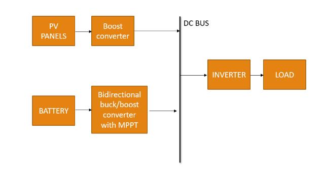
The proposed DC microgrid's overall system configuration is depicted in Fig. 1. It comprises of a common radial DC bus to which the microgrid's numerous parts are connected. In this setup, solar PV is regardedasthemainpowersource.Aboostconverteris alsousedtolinka2.5kWsolarPVarraytothemicrogrid. ThemicrogridsystemprovidesavariableDCload,which couldbeabuildingloadoracollectionofhouseholds.To provide precise control of the microgrid, a centralised BESS is used. In this instance, the battery unit is connectedusingabidirectionalDC DCconverter.
International Research Journal of Engineering and Technology (IRJET) e-ISSN: 2395-0056
Volume: 09 Issue: 07 | July 2022 www.irjet.net p-ISSN: 2395-0072
The DC microgrid's configuration is created such that it can function independently without any connection to theutility.
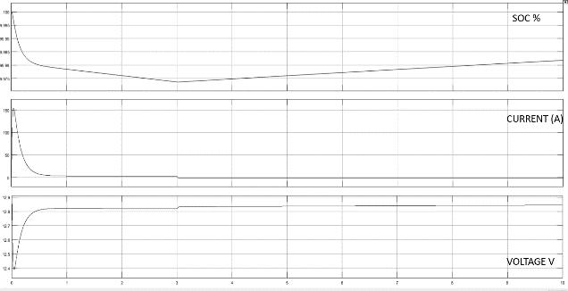
charging or discharging The Fig. 3 is the simulation resultofthebidirectionaldc dcconverterinMatlab.
The thorough modelling processes for each of the microgrid system's components are covered in the sectionthatfollows.
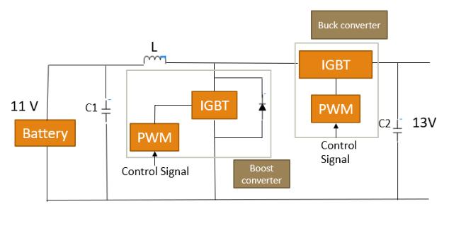
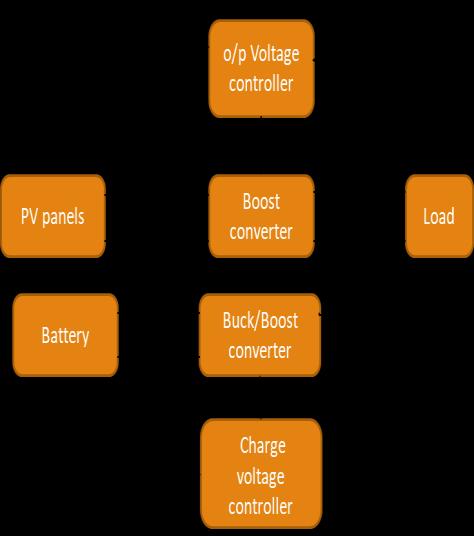
The Battery Storage is connected to the microgrid network using a bidirectional DC DC converter (shown inFig.2).Itsprimarypurposeistoincreasethestability andsecurityofthemicrogrid'soverallperformance.The bidirectionalconverter,asdepictedinthefigure,ismade up of two converters: a boost converter and a buck converter. The Inverted Gate Bipolar Transistors (IGBT) used in each converter are powered by the appropriate Pulse Width Modulated (PWM) signals. The converter's control mechanism is designed to permit a controlled flowofelectricityinbothdirections.Acontrolsignalthat drives the circuit in buck mode is generated during the periodofexcesspower.
We have used step signal at 3 second, therefore we are seeing the change in graph of Soc, Voltage and current. The negative current indicates the discharging of Battery.Itconfirmsthatcharginganddischargingcanbe doneinthisconverter.So wecanusethisconverterand changethevaluesaccordingtoourdcmicrogrid.
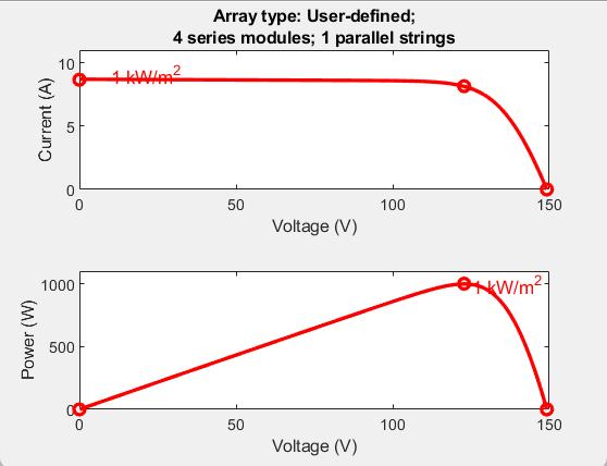
Wehaveusedauser definedPVpanel withfourmodule strings and one parallel string. T is held constant at 25, and the irradiances vary. The simulation will last 2 seconds. Irradiance is 1000 at 0 sec, 300 at 1 sec, and remainsconstantfortherestofthesimulation.
A 2.5kW PV array is utilised for the DC microgrid simulation. A boost converter connects this array to the DC distribution network. The Maximum Power Point (MPPT) tracking algorithm is used by the boost converter. This MPPT capability is essential because it willenablethePVarraytogeneratethegreatestamount of power for a specific irradiation input. The MPPT incremental conductance approach is applied in this situation. One of the key techniques in this system is incremental conductance, a tracked control mechanism that is frequently used due to its improved steady state accuracyandenvironmental adaptability. TheP VandI VcurvesofourPVmodulearedepictedintheFig.4.
It is reducing the 13V DCvoltage to a level that is appropriate for charging the battery unit roughly 11V.When there is a power shortage, the control signal activates the boost converter, which raises the battery voltage to the DCvoltage in order to draw power from the battery. These values are just for analysis of the DC DC Bidirectional converter to show that it can perform
International Research Journal of Engineering and Technology (IRJET) e-ISSN: 2395-0056
Volume: 09 Issue: 07 | July 2022 www.irjet.net p-ISSN: 2395-0072
PointiswherethePVcharacteristiccurveoccurs(MPP). Thispointisalwaysatthesolarpanel'sI Vcurve'sknee. In summation, it can be said that the solar panel's I V curve has a point called the MPP (Maximum Power Point), which is always found at the knee of the curve and is where the amount of PV power produced is at its maximum. This MPP changes as the temperature and radiation levels fluctuate. The MPP tracking algorithm must operate essentially in real time by changing the duty cycle continuously in order to maintain the tracking's speed and accuracy because the irradiation andtemperaturearedynamicinnature.
Fig. 4.I VandP VCurve
A Battery Storage is an electrochemical device that charges (or gathers) energy from the grid or a power plantandthendischargesthatenergywhenelectricityor other grid services are required. We used a lead acid battery with a nominal voltage of 56 volts and a rated capacityof11amperehour.Theinitialstateofchargeis 45 percent and the battery is connected with the bi directionalconvertertotheDCBus.
A negative electrode constructed of spongy or porous lead is used in a lead acid battery. The lead is porous in order to allow lead formation and dissolution. Lead oxide serves as the positive electrode. Both electrodes are submerged in a sulfuric acid and water electrolytic solution.
TheDCmicrogridusesavarietyofcontroltechniquesto function properly regardless of changes in load and generation.Thebuckconverter,whichisthemicrogrid's converter, is operated in a voltage control mode since it is treated as the main source of energy and runs independently. This indicates that the converter's control action is configured to maintain the necessary 200V DC bus voltage when it is in use. While the PV array's controller runs in a current controlled mode to draw the most electricity possible. To get the most current and thus the most power out of the PV circuit, theconverterusestheMPPTalgorithm.
When the solar panel is operating at the voltage where the P V characteristic's global maximum is located, the maximum power (MP) is obtained. It demonstrates that the solar panel can produce its maximum power output at a certain operational point. The Maximum Power
A control device used to keep track of the MPP's continual change is called the Maximum Power Point Tracker (MPPT). This control system or controller is made up of two primary components: a converter that changesthegeneratedvoltagetothecorrectlevelforthe load and a microcontroller that tracks the MPP. On the microcontroller, analgorithmis being usedto track the MPP. Numerous alternative algorithms are employed to track the MPP, but none of them are effective in rapid fluctuations, such as rapidly changing irradiance levels orwhenthesolarpanelispartiallyshaded.However,itis crucial for the system to have an algorithm that can deliver precise control signals even when irradiance levelsarerapidlychangingorthesolarpanelispartially shaded. Therefore, the algorithm's effectiveness is crucial.
The MPPT controller uses the algorithm to determine the MPP. The controller accepts as inputs the measured output voltage and current of the solar panel. The algorithm performs its calculations depending on these inputs. The controller generates an output that is the PWM's modified duty cycle. It powers the switching component of the DC/DC converter. The controller generates a separate duty cycle for each each operating point.
TheslopeoftheP Vcurveisdetectedbytheincremental conductance technique, and the MPP is monitored by seeking the peak of the P V curve. For MPPT, this technique use the instantaneous conductance I/V and theincrementalconductancedI/dV
The Perturb & Observe Algorithm is enhanced by the Incremental Conductance Algorithm. Particularly in the face of changing atmospheric circumstances, our algorithm guarantees greater accuracy and efficiency. Despite these benefits, there are a few disadvantages to this method, including a longer response time and the factthatsmall scalePVplantscannotaffordit.Whenthe perturbationand tracking processreachestheMPP,this
International Research Journal of Engineering and Technology (IRJET) e-ISSN: 2395-0056
Volume: 09 Issue: 07 | July 2022 www.irjet.net p-ISSN: 2395-0072
Mode. 1: When PPV < PL, which indicates that there is insufficient solar power, the PV panels operate in MPPT mode under the control of the boost converter. Meanwhile, the battery provides the complementary power using the bidirectional buck/boost converter, which is operating in boost mode to control the DC bus voltageVo (thereferencedirectionisshownasinFigure 6.a).
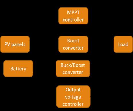
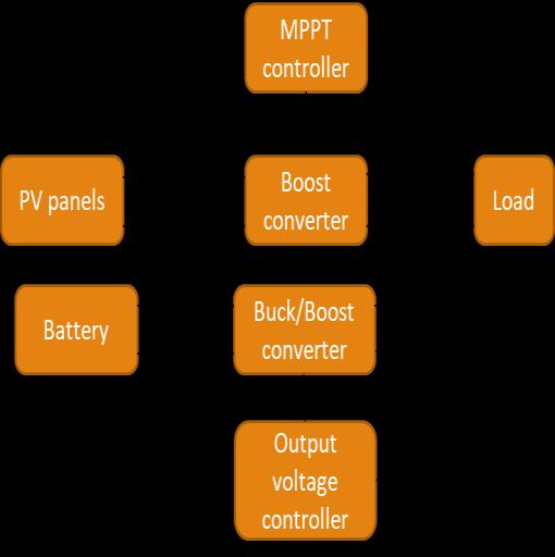
Fig. 5(a)
Mode. 2: The PV panels run in MPPT mode under the supervision of the boostconverter when PPV > PL, which denotes an excess of solar power. Bidirectional buck/boost converter is running in boost mode to control the DC bus voltage Vo while the battery is being chargedbycomplementarypowerutilisingtheconverter (thereferencedirectionisshownasinFigure6.b).
Fig. 5(b)
Mode. 3: Ibat must be managed to protect the battery when Ppv > PL and it hits the maximum charging current limit, Ibmax. As a result, the bidirectional buck/boost convertercontrolsibatwhenoperatinginbuckmode.As seen in Figure c, the PV panels must transition out of MPPTcontrolmodeandmanagethedcbusvoltage.
Fig. 5(c)
Mode. 4: The bidirectional converter will work in buck mode to control Vbat when PPV > PL and Vbat reaches the maximum battery voltage limit Vbmax. The boost converter continues to control Vo at the same time, as seeninFigure6.d.
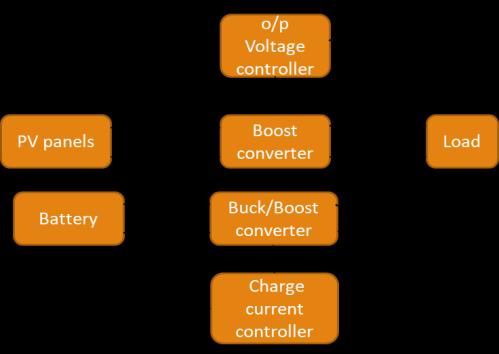
Fig. 5(d)
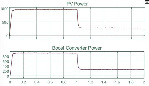
AsimulinkmodelofaDCmicrogridisconstructedusing themodelsofitsnumerous components.Avariableload with a maximum demand of 6 kW is considered for the simulation's purposes. Solar radiation inputs are provided to the solar PV array model. The microgrid is then the subject of a simulation study under various operationalconditions.Thesimulationsareperformedin this example for a total of 2 seconds. We operate our system at 1000 watts per square metre for the first 1.0 secondsbeforeswitchingto300wattspersquaremetre fortheremaining1.0seconds.
Initiallywetooktheirradianceas1000 wattsper metre square. That means MPPT should extract the maximum power around 1000 watts per metre square. After 1 second you can see the change in the graph as we have shifted our system from 1000 to 300 watt per metre square.
e-ISSN: 2395-0056
Volume: 09 Issue: 07 | July 2022 www.irjet.net p-ISSN: 2395-0072
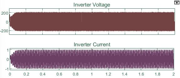
Here,youcanseethatthegraphisstaticofbothvoltage and current, indicating that the AC load is receiving powerwithoutinterruption.
Fig. 6(a)
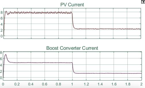
Asyoucansee,theinitialcurrentatthePVis8Amperes. For around 1 second, it oscillates between 8 and 6 Ampere before becoming somewhat steady. After 1 seconds, when we reduce the irradiance from 1000 to 300 watts per square metre, it reduces to around 2 Ampere.
Initial boost converter current was 7 amperes, but it swings and drops to around 4.7 amperes in the first second.Whentheirradianceischangedto300wattsper square metre from 1000 watts per square metre, it remainsconstantformorethan0.9secondsanddropsto around1.7ampsat1second.
Fig. 6(b)
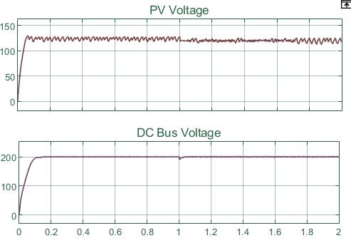
The MPPT voltage level is maintained as the PV voltage. Additionally, the DC Bus voltage is kept at or near the refrencevoltage,or200volts
Fig. 6(c)
Fig 6(d)
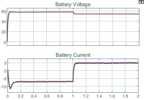
56 volts were initially present in the battery, and this voltage was held for about 1.0 second. But when the irradianceischangedfrom1000to300wattspersquare metre,thevoltagesomewhatreducestoroughly53volts.
The fact that the battery's first current was negative indicates that the battery was originally charging. But thecurrentturnspositivewhentheirradianceisreduced from1000to300wattspersquaremetreat1.0seconds. Consequently, the battery began to discharge at1.0 seconds after the irradiance was changed from 1000 to 300wattspersquaremetre.
Fig. 6(e)
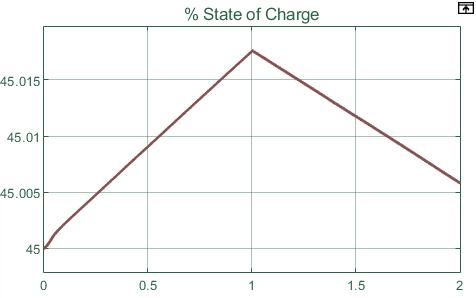
The battery'sinitial SOC,as shown in the figure, wasset at 45%. The battery was charging for the first 1.0 secondswhiletheirradiancewasaround1000wattsper squaremetre.
However, as the irradiance changes from 1000 to 300 after1.0seconds,thebatterydischargesduringthefinal 1.0seconds,indicatingthatthebatteryisnowsupplying energytothesystemsinceitisrunninglow.
International Research Journal of Engineering and Technology (IRJET) e-ISSN: 2395-0056
Volume: 09 Issue: 07 | July 2022 www.irjet.net p-ISSN: 2395-0072
[5] T. Esram and P. Chapman, “Comparison of Photovoltaic Array Maximum Power Point Tracking Techniques,” IEEE Trans. On Energy Conversion,vol.22,no.2,2007.
[6] V. Agarwal H. Patel. Maximum power point trackingschemeforpvsystemsoperatingunder partially shaded conditions.IEEE Trans.Ind,55:1689 1698,2008.
Fig. 6(f)
With the help of Matlab Simulink, a self sufficient DC microgrid is developed and put into operation. As a result of their apparent simplicity of control and increased efficiency, DC microgrids are the focus of this paper.TheanalysisoftheDC DCbidirectional converter and DC microgrid revealed that they successfully produce the outcomes we require. And from this research, it can be inferred that a DC microgrid's design is far more straightforward and reliable than its corresponding AC version. To improve the batteries' charging and discharging modes while utilising a bidirectional DC DC converter, more thorough investigationisneeded.
[1] P. Sanjeev, N. P. Pandhy and P. Agarwal, “Effective control and energy management of isolated DC microgrid,” 2017 IEEE Power & Energy Society General Meeting, Chicago, IL, USA,2017
[2] P. Sanjeev, N. P. Pandhy and P. Agarwal, “Autonomous Power Control and Management Between Standalone DC Microgrids,” in IEEE Transactions on Industrial Informatics, vol. PP, no.99.2017.
[3] S.Chowdhury,S.P.Chowdhury,andP.Crossley, Microgrids and active distribution networks: Stevenage: Institution of Engineering and Technology,2009.
[4] Mirza Mursalin Iqbal, Kafiul Islam, “Design And SimulationOfAPVSystemWithBatteryStorage Using Bidirectional DC DC Converter Using Matlab Simulink, ” International Journal of Scientific & Technology Research Volume 6, Issue07,JULY2017.
[7] Bharath K R, Harsha Choutapalli, KanakasabapathyP“ControlofBidirectionalDC DCConverterin Renewable based DC Microgrid with Improved Voltage Stability” in International Journal of Renewable Energy ResearchJune,2018.
[8] Nihad Abdulkhudhur Jasim, Majli Nema Hawas “Modelling and simulation of microgrid power system including a hybrid energy storage system” Middle Technical University, Baghdad, Iraq,2020.
[9] Srikanth Kotra, Mahesh K. Mishra “Design and Stability Analysis of DC Microgrid with Hybrid EnergyStorageSystem”inIEEE,2019.
[10] C. Phurailatpam, R. Sangral,B.S. Rajpurohit, S.N. Singh,F.G.Longatt,“DesignandAnalysisofaDC Microgrid with Centralized Battery Energy StorageSystem”conferencepaper,dec2015.
[11] Y. Wang, K. T. Tan, and P. L. So, "Coordinated control of battery energy storage system in a microgrid," in Power and Energy Engineering Conference (APPEEC), 2013 IEEE PES Asia Pacific,2013.
[12] M. Kumar, S. N. Singh, and S. C. Srivastava, "Design and control of smart DC microgrid for integration of renewable energy sources," 2012 IEEE Power & Energy Society General Meeting, p. 1,2012.