International Research Journal of Engineering and Technology (IRJET) e ISSN: 2395 0056
Volume: 09 Issue: 07 | July 2022 www.irjet.net p ISSN: 2395 0072

International Research Journal of Engineering and Technology (IRJET) e ISSN: 2395 0056
Volume: 09 Issue: 07 | July 2022 www.irjet.net p ISSN: 2395 0072
Abstract It is a known concept that having bluff bodies in tandem(besides) may reduce the drag generated by single bodies comparatively. Many experimental and numerical researches [2] [13] had undertaken and is being in process in order to reduce the drag experiencedbythe body. Similarlya V shaped gutter is a one type of flame stabilizers being used in afterburner of an aircraft gas turbine engine with main purpose to hold the flame in an afterburner These after burners were used in combat missiles to provide an extra impact thrust for a limited period of time . But when the burner is not under use the presence of V gutter shaped flame stabilizers creates an excess drag also creates some excess drag force. Hence it is necessary to reduce the drag created by these V gutter. In this work an attempt has been made to study about the flow separation [7] characteristics ofV gutter also a different varities of modified V flame stabilizers were analyzed The flow simulation is done using CFD FLUENT FLOW.
Key Words: Reynolds number, Turbulent flow, Flow separation,DragCoefficient,fterburnerflame,Drag,Aerofoil shapegutter,v shapedgutter,tandembodies
Inaircraftapplication,largeramountof thrustfor smalldurationisrequiredinordertoprovidesuddenimpact forcemajorlytherearetwomethodsavailabletoattainthese impactforce.Firstmethodisbydirectlyincreasingthemas flowrateandtheotherisbygeneratingthrustaugmentation. InanafterburnermajorpurposeofFlamestabilizingand to hold and the flames, which are placed after the turbine section in an afterburner. Generally Bluff bodies are characterized bya large regionofseparatedflow,a direct consequenceofwhichisthattheysufferfromlargevaluesof Cd. Various research and development are carried out to improvetheperformanceofafterburner[2]numericallytoo, by reducing the drag created by these bodies both experimentallyandtheoretically.InrecentlyComputational methodshavebecomehighlyusefultooltodesign,develop, modify and finally analyze the performance of an afterburner[1].The amount of drag generated by the presenceofboundarylayerformationandboundarylayer separation offlamestabilizerandtherecirculationzonesin
***
thewakeofthestabilizerplaysveryimportantfactortobe consideredforbetterperformanceofanafterburnerinany gasturbineengines.Inthepast,variousresearchactivities havebeencarriedouttoreducethedragofbluffbodies[11], byvaryingtheorientationandarrangementofthebluffbody suchas,tandem,staggered,normal,andperpendiculartothe flow.Theabove researches were carriedoutthroughCFD using ANSYS fluent software. A brief review of literature relatedtotheabovestudiesarepresented.
Initially,formervarious casestudiesonthevarioustypesof flamestabilizergeometriesaredone.
The design parameters and the boundary conditions for analysispurposesaredetermined.•

Modelling of various types of V gutters were done on considering the factors which affects drag property using ANSYSFLUENTFLOWworkbench.
MeshingandValidationofthedragforceofnewlymodified modelisundergonewithreferencetoboundaryconditionsof referencejournals.[16]
Dragvaluesfromvarious researchpaperiscomparedwith the CFD analysis value done in our software by taking the sameboundarycondition.[20]•
2022, IRJET | Impact Factor value: 7.529 | ISO 9001:2008 Certified

International Research Journal of Engineering and Technology (IRJET) e ISSN: 2395 0056
Volume: 09 Issue: 07 | July 2022 www.irjet.net p ISSN: 2395 0072
ThefluidflowanalysisisdoneusingAnsysFLUENTtoobtain forces acting on the geometries and Drag coefficient is calculatedusingDragEquation.Ifrequired•
The results are compared and optimum results for better performanceofafterburnerischosen.
ANSYS fluent software is used for the computational fluid dynamicsanalysisofflowoveraV gutter.
A steady flow with viscous flow is considered and k ɛ turbulence model is taken for the analysis. Standard wall functionischosenwithv gutterasnoslipwall.[18]
Acomputationalfluiddomainiscreatedsurroundingthev guttermodelwhichistakenfromtheliteraturesurveywhich correspondstothesectionofanafterburnerTheanalysisis carriedoutforthethreedifferentconfigurationofthebluff bodieseachhavingthreedifferentcases.
Dragcoefficientiscalculatedusingthedragforceobtainedby thesoftwareinthedragequation.
Table -1: Boundarylayerconditionparameters
Boundarylayerconditionparameters
Parameters value
Inletvelocity 220m/s
Inletgaugepressure 124075N/m^2
Turbulencekineticenergy(k) 187.8m^2/s^2
Turbulencedissipationrate(ɛ) 655.57m^2/s^3
Outletgaugepressure 122675N/m^2
Turbulencelevel(%) 5
Ratioofspecificheat(ɤ) 1.35 Temperature 1009.1K
DragEquationisusedtofindthedragcoefficient.[20]
Cd=Fd0.5∗ρ∗v2∗A
Where,Cd CoefficientofDrag.
Fd DragforceinNewton.

A Projectedareaonaplaneperpendiculartothedirection ofmotioninm2.
ρ DensityofthefluidinKg/m3.
v Velocityofthefluidinm/s.
Fig 02: schematicdiagramofFlame stabilizer
Coefficient of drag is calculated and flow over the bare v gutterandwhenthebluffbodiesareplaceddownstreamare observed. Three different configurations were studied consideringthefactorsaffectingthedragandcompared.The results show reduction of drag over the v gutter with the bluff bodies placed downstream when compared with the barev gutter.

CFDsimulationofflamestabilizershavebeencarriedoutfor all three different models angled geometries. Industrial scaledgeometriesareexposedintoFLUENTandactualplant operating conditions are taken as input to validate the results.
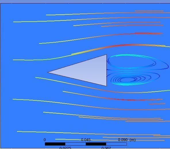
CFD predictions have been carried out with gutter kept normaltotheflow.Thevelocityvariationandflowpattern areshowninthefigure.Thedragforcewasfoundfromthe forcesummaryoutputfromtheCFD ACE+analysissoftware along the direction of flow over the gutter. For V gutterof modified model 01 the dragforce iscalculate using set up tool in ANSYS FLUENT FLOW with an iteration of 1000, initialized and the graph is plotted with drag force and respectediterations,fromthegraphastandardvalueofdrag forceisachieved
Fig 03: CFDMODELOFCURVERBODYV GUTTER
International Research Journal of Engineering and Technology (IRJET) e ISSN: 2395 0056
Volume: 09 Issue: 07 | July 2022 www.irjet.net p ISSN: 2395 0072
Inthismodel,wecanobservethattheflowisoccurred always,alongthebodyofv gutter,fromtheANSYS FLUENT flowsoftwarethedragforceiscalculatedtobe1197.2188N valuealongwiththatfromstreamlineflowdiagramitisseen that the flow of particles is along the body without any deviation[17]anyhowdragforceiscreatedbyswirlmotion oftheflowmedium
Case 2) LINEAR BODY(MODEL 02):

Withreferencetothedragforceobtainedfromtheprevious modified model, a new model is to be created with same boundaryconditionsandotherpropertiesCFDpredictions [14]have been carried out with gutter kept normal to the flow, thus this model should be analyzed using ANSYS FLUENTFLOWsoftwaretocalculateitsdragforce.


In this modified model 02 V Gutter, moreover the flow is alongthebodyofv gutter,beyondthattheboundarylayer separationpoint[17]andflowofseparationwasmarginally reducedthanpreviousmodel,fromtheANSYS FLUENTflow softwarethedragforceiscalculatedtobe1128.4947Nvalue.
Inordertocompareandanalyzetheresultofour modified flame stabilizer model, a commercially available modeloranystandardmodelofflamestabilizershouldbe created and analyzed using ANSYS FLUENT software [14] underthesameboundaryconditionparameters
Fig 07: CFDMODELOFORIGINALBODYV GUTTER
International Research Journal of Engineering and Technology (IRJET) e ISSN: 2395 0056
Volume: 09 Issue: 07 | July 2022 www.irjet.net p ISSN: 2395 0072
visibleinstreamlinediagram.Becauseofflowseparationis verymuchlessertheturbulenceisreducedandhencedragis reduced[4].
Also,bytheearlierre attachmentofthestreamtakesplace, theflowseparationis considerablyreducedthanmodel02 V gutter.
Hence by creating a modified linear body with aero foil characteristics,wecanconsiderablyreducethedragforceby increasingtheareaofflowparticlesbywhichtheboundary layerseparationismarginally
S.NO BODY DRAG FORCE(N)
1 MODEL01 1197.2188
Behindthepreviousmodel,thisoneisanexistingavailable model, for the comparable data and to verify our better results.ThisbodyisalsoanalyzedusingANSYS FLUENTthen itsdragvalueiscalculatedtobe1190.375N.Thenfromthe streamlinediagramwecanclearlyobservedthatdragforce createdismorethanothertwomodels,becauseofbackflow motion of particles and swirl motion of those particles boundary flow separation takes place easily and the re attachment point was located far away, hence more drag forceiscreated.
After the overall results are achieved and analysis is completedthecomparisonhasbeenmade.Thecomparison formodel02vgutteritcanbeseenfromwhichismodified aero foil shape gutter is more efficient in drag reduction when compare to other cases. When v gutter shape is requiredthenmodel02isbetterthanotherone.Comparing theaboveresults,itcanbesaidthattheaerofoilshapegutter ismoreefficientthanthev guttershapeflamestabilizer.
Butinmodel03thedragforcecreatedismore,becauseof flow separation[3]ofstreamtakesplaceatearlierandpoint ofre attachmentisfarawaythanothertwomodelsandin model01thedragforcecreatedwasconsiderablylargerthan othermodel.
Dragforceiscreatedinboththemodelcreatedbutinmodel 02V gutterasbecausetheflowseparationtakesplaceearlier becauseofitsaerofoilturbulenceiscreatedwithinthebody ofV gutterhencesomereversedflowstreamiscreatedthat causesanegativepressurealongthebodyofV gutter[10], alsothecompleteabsenceofre attachmentpointsalsomade itmoreturbulent.
Asbecauseofangularchangestheflowseparationtakesplace atbeyondsomeregionsofthemodel02V gutter,isclearly
2 MODEL02 1128.4947
3 MODEL03 1190.375
InthisprojectworktheanalysisofdragforceofaV gutter wasdone,usingCFDFLUENTFLOW,inordertoreducethe dragforceinanafter burnerflamestabilizer,researchand development are carried out improve the performance of afterburner, both experimentally and theoretically. Computationalmethodshavebecomehighlyusefultoolto design, develop, and analyze the performance of an afterburner before implementing. The amount of drag generated by the presence of flame stabilizer and the recirculation zones in the wake of the stabilizer are very importantfactortobeconsideredforbetterperformanceof an afterburner in any gas turbine engines These type of flamestabilizers wereavailableinvarious models.By our workwecanconcludethatV gutterofmodifiedmodels is moreefficientindragreductioninafterburnerbecauseofits lesserturbulence,areabetweenthe flowseparationandre attachmentpointisconsiderablyreducedinitssurfaceand hencelesserdragforceisachieved.
ItcanbeconcludedfromtheCFDanalysisthatthedragcan be reduced by placing the bluff bodies tandem to the V gutter. It can be observed from our above work that modified gutter is experienced with lesser drag force also clearlyexplained .Consideringtheabovethreecasesit is goodtouseaerofoilshapelineargutterinplaceofv gutteris used,. Thus taking performance of the afterburner as consideration the suitable gutter has to be used as flame stabilizerintheafterburnersection
International Research Journal of Engineering and Technology (IRJET) e ISSN: 2395 0056
[1] S Srinivasan, J J Isaac, C.Rajashekar, A.Arokkiaswamy, Aug 2012 DragreductionofVgutterofanafterburner by tandem bluff bodies using CFD, OSR Journal of MechanicalandCivilEngineering(IOSRJMCE).
[2] Anand R, Lokesharun D, Rajkumar S, Kirubakaran R 2017 “3D CFD Analysis In An Afterburner Using Numeca”.InternationalJournalofAdvancedResearchin Engineering&Management(IJAREM).
[3] Parammasivam K M, K. Kirubhakaran,” Experimental StudiesonBehaviorofFlameStructureduetoVortexin V Gutter Combustors (AIAA 2015 4090)”, 51st AIAA/SAE/ASEE Joint Propulsion Conference, 2015, 10.2514/6.2015 4090,July28,Florida,USA
[4] Parammasivam K M,S.Subaramanian, Sai P Suganth, Shaik Shahabaz Ahamed and ( 2015),“Experimental StudiesOfFlameHoldingIn ColdFlows”,2ndNational PropulsionConference,2015,OrganizedbyIITBombay, 23 24,February2015
[5] Amitay,M.andGlezer,G.,“ControlledTransientsofFlow
Reattachment Over Stalled Airfoils,” International JournalofHeatandFluidFlow,Vol.23,2002,pp.690 699.
[6] Mueller,T.J.andBatile,S.M.:Experimentalstudiesof separationonatwo dimensionalairfoilatlowReynolds numbers,AIAAJournal,20 4(1982).
[7] Lian,Y.andShyy,W.:Laminar TurbulentTransitionofa Low Reynolds Number Rigid or Flexible Airfoil, AIAA Journal,45 7(2007),1501 1513
[8] P.F.Zhang, J.J.Wang, S.F.Lu.J.Mi, Aerodynamic characteristics of square cylinder with a rod in staggeredarrangement,ExperimentsinFluids,Volume 38,Issue4,pp.494 502,March 2005.
[9] Umyshev,D.R.,etal.,ExperimentalInvestigationofV gutterFlameholders,ThermalScience,21(2017),2,pp. 1011 1019
[10] Umyshev,D.R.,etal.,ApplicationofSemiPerforatedV gutter Flame holders in Heat Generating Systems for AutonomousBuildingHeating,InternationalJournalof MechanicsandMechatronics,16(2016),6,pp.63 69
[11] Schefer, R., et al., Effect of Confinement on Bluff Body BurnerRe CirculationZoneCharacteristicsandFlame Stability,Combust.Sci.Technol.
[12] Tang, H., et al., Characteristics of Flame Modes for a Conical Bluff Body Burner with a Central Fuel Jet, JournalEng.GasTurbinesPower,135(2013)
[13] Aiwu,F.,etal.,NumericalInvestigationonFlameBlow off Limit of a Novel Microscale Swiss Roll Combustor withaBluff Body,Energy,123(2017),Mar.,pp.252 259
[14] Steven, Tran., et al., Finite Element Based Large Eddy Simulation of Flow over Bluff Bodies, Computers and Fluids,158(2017),Nov.,pp.221 235
[15] Bikram,R.etal.,EffectsofFreeStreamFlowTurbulence on Blowoff Characteristics of Bluff Body Stabilized PremixedFlames,CombustionandFlame,190(2018), Apr.,pp.302 316
[16] Birkam, R., et al., Experimental Study of the Effects of Free StreamTurbulenceon CharacteristicsandFlame Structure of Bluff Body Stabilized Conical Lean PremixedFlames,CombustionandFlame,178(2017), Apr.,pp.311 328
[17] Nicholson,H.M.,Fields,J.P.,SomeExperimentTechnikal for the Investigation of the Mechanism of Flame StabilizationintheWakesofBluffBodies,Proceedings, 3rdIntl.Sympos.onComb.,WilliamsandWilkensCo., Baltimore,USA,1949,pp.44 48
[18] Dawson, J.R., et.al,Visualization ofBlow offEvents in Bluff Body Stabilized Turbulent Premixed Flames, ProceedingsoftheCombustionInstitute,(2011)
[19] Gan,D.,et.al.,StudyontheVortexSheddingMechanism of Coupling Combustion Stabilizer with V gutter and Strong Swirl Flow, Proceedings, 2014 Asia Pacific International Symposium on Aerospace Technology, APISAT2014,Shanghai,China,2014
[20] Rakesh.C1,JafarMSayed2,MSGaneshaPrasad31Dept. of Mechanical Engineering, New Horizon College of Engineering,,Int.J.HydrogenEnergy,38(2013),26,pp. 11438 11445.
[21] Watkins,S.,Mohamed,A.,Fisher,A.,Clothier,R.,Carrese, R.andFletcher,A.:TowardsAutonomousMAVSoaringin Cities: CFD Simulation, EFD Measurement and Flight Trials, International Journal of Micro Air Vehicles, (2015),441 448.
[22] Brzozowski, D. P., Woo, G. T. K., Culp, J.R., Glezer, A., “TransientSeparationControlUsingPulse Combustion Actuation,”AIAAJournal,Vol.48,No.11,2011,pp.2482 2490.
[23] Amitay,M.andGlezer,G.,“ControlledTransientsofFlow Reattachment Over Stalled Airfoils,” International JournalofHeatandFluidFlow,Vol.23,2002,pp.690 699.
[24] Williams,D.,Kerstens,W.,Pfeiffer,J.,King,R.,Colonius, T., “Unsteady Lift Suppression with a Robust Closed
Volume: 09 Issue: 07 | July 2022 www.irjet.net p ISSN: 2395 0072 © 2022, IRJET | Impact Factor value: 7.529 | ISO 9001:2008 Certified Journal |
International Research Journal of Engineering and Technology (IRJET) e ISSN: 2395 0056
Volume: 09 Issue: 07 | July 2022 www.irjet.net p ISSN: 2395 0072
LoopController,”ActiveFlowControlII,NNFM,Vol.108, 2010,pp.19 30.
[25] Thake,M.P.,Packard,N.O.,Bonilla,C.H.,Gompertz,K. A., and Bons, J. P., “Reynolds Number Scalability for Separation Control on a Laminar Airfoil,” 49th AIAA AerospaceSciencesMeeting,Orlando,FL,4 7Jan.,2011.
[26] Rethmel, C., Little, J., Takashima, K., Sinha, A., Adamovich, I., Samimy, M., “Flow Separation Control over an Airfoil with Nanosecond Pulse Driven DBD Plasma Actuators,”49th AIAA Aerospace Sciences Meeting,AIAA2011 487,Orlando,FL,4 7Jan.,2011.
[27] Flohr,P.andPitsch,H.,2000,Aturbulentflamespeed closure model for LES of industrial burner flows.Proceedingsofthe2000CTRSummerProgram,p. 169 179.
[28] Abdel Gayed,R.G.,Al Khishali,K.J.andBradley,D.,1984, Turbulent burning velocities and flame straining in explosions. Proceedings of the Royal Society, London, A391,393 414.
[29] Karpov,V.P.,Lipatnikov,A.N.andZimont,V.L.,1994,A model for premixed turbulent combustion and its validation.ArchiviumCombust.,4,125 141.
[30] Raushenbah,B.V.,Bely,C.A.,Bespalov,I.B.,Borodachev, B.Ja.,Bolinsky,M.S.,andPrudnikov,A.G.,1964,Physical PrinciplesoftheProcessesinCombustionChambersof Air Breathing Jet Propulsions (Moscow: Mashinostroenie),p.265 280(inRussian).
[31] Dinkelacker,F.andH¨olzer,S.,2000,Investigationofa turbulent flame speed closure approach for premixed flames calculations. Combustion Science and Technology,158,321 340.
[32] Zimont, V.L., 2000, Gas premixed combustion at high turbulence.Turbulentflameclosurecombustionmodel ExperimentalThermalandFluidScience,21,179 186
[33] Biagioli, F. and Zimont, V.L., 2002, Gas dynamics modelling of counter gradient transport in open and impinging turbulent premixed flames. Proceedings of the29thInternationalSymposiumonCombustion,pp. 1207 1214,TheCombustionInstitute.
[34] Zimont,V., Polifke,W., Bettelini, M. andWeisenstein,W., 1998, An efficient computational model for premixed turbulentcombustionathighReynoldsnumbersbased onaturbulentflamespeedclosure.Transactionsofthe ASME,120,526 532.
[35] Dinkelacker,F.,Soika,A.,Most,D.,Hofmann,D.,Leipertz, A., Polifke,W. and D¨obbeling, K., 1998, Structure of locallyquenchedhighlyturbulentleanpremixedflames.
Proceedings of the 27th International Symposium on Combustion,pp.857 865.TheCombustionInstitute.
© 2022, IRJET | Impact Factor value: 7.529 | ISO 9001:2008 Certified Journal |