International Research Journal of Engineering and Technology (IRJET) e ISSN: 2395 0056


International Research Journal of Engineering and Technology (IRJET) e ISSN: 2395 0056
1 M.E. Scholar, Department of Mechanical Engineering, Faculty of Technology and Engineering, The Maharaja Sayajirao University of Baroda, Vadodara
2 Assistant professor, Department of Mechanical Engineering, Faculty of Technology and Engineering, The Maharaja Sayajirao University of Baroda, Vadodara ***
Abstract - Abrasive water jet machine (AWJM) is a nonconventional machining technique in which, material removal takes place from the work piece by impact erosion. High pressure and high velocity water jet mixed with abrasive material to provide smooth surface finish. Abrasive Waterjet (AWJ) cutting has proven to be an effective technology for material processing with the distinct advantages of no thermal distortion, high machining versatility, high flexibility and small cutting forces. In the currentstudy,aBox Behnkendesignoftheresponsesurface methodology (RSM) was used to investigate the performance of the abrasive water jet machining (AWJM) of INCONEL 718.The nozzle traverse speed, abrasive mass flow rate and standoff distance were selected as AWJM variables, whereas the material removal rate (MRR), kerf width and kerf taper angle (θ) were considered as output responses. Statistical models were developed for the response, and Analysis of variance (ANOVA) was executed for determining therobustnessofresponses.
Key Words: Abrasive waterjet machining (AWJM); Response surface methodology (RSM); Box Behnken; ANOVA;Optimization;Material removal rate (MRR); Kerf width;Kerftaperangle.
It is very difficult to machine an alloy using traditional machiningmethodsbecauseofitshighstrengthandwork hardening nature. Hence non traditional methods like electrochemical machining, ultrasonic machining, electro discharge machining (EDM), Wire cut Electro Discharge Machining (WEDM), water jet machining (WJM), Abrasive water jet machining (AWJM), Ultrasonic Machining(USM), Electron beam machining (EBM), Laser beam machining (LBM)etc.areused[1,2]IRJET.Inconel 718isoneamong the family of nickel chromium based super alloys which are having high strength, corrosion resistant used at 217°C to 704°C extreme temperatures [3]. Inconel 718 having 8mm thickness is studied in the present investigation.
Thesuitableprocessmodeltomachiningnickel chromium based super alloys was found to be Abrasive water jet machining, because it has no thermal influence on
machining material. Abrasive water jet can machine a various range of materials such as metal matrix composites(MMC),superalloys,Titaniumalloys,stainless steel, ceramics, and plastics etc. The Cutting time is faster but cost per cutting is relatively high. Abrasive waterjet machining (AWJM) is one of the most widely used non traditional processes in industries for the machining of hard materials [4.5,6]. AWJM has a high cutting speed, ensures high accuracy and flexibility, has no heat affected zone, and is eco friendly [7,8]. Some of the other advantages include the low machining cost, ease in programming, and conservation of properties due to a lowertemperatureduringmachiningandthewiderangeof machinablematerials[9,10,11].InAWJM,thehighvelocity and pressured water jet mixed with abrasives target the workpiece leading to erosion of the material. Some of the limitations of AWJM include the development of surface roughness,kerftaper,delamination,abrasiveembedment, etc.,whichresultsinpoorqualityofthemachinedpart[7]. The use of optimized AWJM process parameters can reduce these limitations. A considerable amount of work has been conducted in recent years to study the mechanism of AWJ cutting and to develop kerf geometry and surface roughness models for process control and optimization. These have involved the processing of ductileandbrittlematerials,leathers,woodsandrubbers, aswellascompositesandlayeredcomposites.
B. Satyanarayana et al. optimized the value of MRR and kerf width simultaneously of AWJM process on INCONEL 718alloyusingTaguchigreyrelationalanalysisaccurately. Minitab17wasusedforanalysispurpose.Water pressure is the most influencing process parameter for MRR and Kerfwidth[12].
Reddyetal.[13]investigatedmultiobjectiveoptimization using WASPAS and MOORA techniques for input controllableparametersofAWJMsuchasTS,AFRandSOD whichinfluencesperformancecharacteristicsofMRR,kerf width, and SR. They performed experiments on the Inconel 625 workpiece. They found that MRR was positively varying with TS and AFR. SR was increasing
Volume: 09 Issue: 07 | July 2022 www.irjet.net p ISSN: 2395 0072 © 2022, IRJET | Impact Factor value: 7.529 | ISO 9001:2008 Certified Journal
International Research Journal of Engineering and Technology (IRJET) e ISSN: 2395 0056
Volume: 09 Issue: 07 | July 2022 www.irjet.net p ISSN: 2395 0072
withanincreaseinAFRanddecreasingwithanincreasein TS
Thakkar et al. worked on optimization of machining parameters on Material removal rate and Surface roughnessofworkpieceofMildSteel[14], StainlessSteel 403 [15], red mud reinforced banana/polyester hybrid composite [16], Inconel 718 [17,18], Inconel 800H [19], mild steel [20], ductile material such as AISI 4340, Aluminum2219[21] using Taguchi’smethod
Vinod B Patel [22], investigated the influence of AWJM process parameters on response MRR and Ra of EN8 material based on Taguchi’s method and analysis of variance.Theyfoundthatvaryingparametersareaffected indifferentwayfordifferentresponse
Pravin R. Kubade, Pranav Potdar, Ravindranath G. Kshirsagar [23] worked on optimization of the process parameters on abrasive water jet machining for Inconel 718materialbytakingMaterialremovablerate(MRR)and surface roughness (SR) as responses. Traverse Speed (S) plays a vital role on influencing material removable rate (MRR) by 90.27% as observed in ANOVA test. Then the majorcontributiononMRRisabrasiveFlowRatewhichis about 5.97%. We also observed that Standoff distance is sub significant in influencing MRR. In case of surface RoughnessAbrasiveFlowRatemajorsignificanceofabout 42.51%. Traverse speed and Standoff distance having sub significance influence on SR by 25.49% and 22.09 % respectively. The confirmation experiments were conducted using the optimum combination of the machiningparametersobtainedfromTaguchianalysis.
The material removal rate (MRR) increases with increase in standoff distance because of abrasive jet particles impacts deeper on work surface which creates craters [24]. Lower traverse speed also influences in higher materialremovalrate(MRR)[25].
In this investigation, the work material Inconel 718 was used. The workpiece was procured from BHARAT AEROSPACE METALS, Mumbai, India. The chemical composition of the workpiece examined by spectroscopic analysisisgiveninTable1.
Table 1: ChemicalCompositionofINCONEL718
Ahmedabad.ThemachineusedforsampleswasWaterJet Model:DWJ1525 FAwhichisequippedwithSL V50PLUS pressure pump with the designed pressure of 3900 bar. The machine is equipped with a gravity feed type of abrasive hopper, an abrasive feeder system, a pneumatically controlled valve and a work piece table withdimensionof3000mmx3000mm. Sapphireorifice was used to transform the high pressure water into a collimated jet, with a carbide nozzle to form an abrasive waterjet.

TheAbrasive Water JetMachining hasbeen conducted on 3 axis machine (ADTECH CNC4640) with CNC programming at BALAJI Enterprise, vatva GIDC,
Factor value:
Figure 1:ExperientialsetupofAWJMprocessusedin currentstudy
Constant Parameters :
Nozzlematerial:ROCTEC100CompositeCarbide
Nozzlediameter:1.02mm
Orificematerial:Sapphire
Orificediameter:0.33mm
Impactangleofjet:Neutralnozzleposition(90°)
WaterPressure(P)Bar:3900Bar
Typeofabrasivematerial:Garnet
Meshsizeofabrasive:80mesh
International Research Journal of Engineering and Technology (IRJET) e ISSN: 2395 0056
Volume: 09 Issue: 07 | July 2022 www.irjet.net p ISSN: 2395 0072
In most of the literature surveyed, two performance parameters, namely, MRR or cutting rate and Kerf width, were the most important performance measure for investigating the machinability of a material by AWJM. In the present study, Kerf taper angle is also included as a performance measure. Thus, in this experimental work MRR, Kerf width and Kerf taper angle are considered as responseparameters.

The material removal rate (MRR) of the work piece is the amount of the material removed per minute. MRR and Cutting speed capabilities of AWJM have increased enormously over the years. MRR is measured on weight basesorvolumebases.
TheMRR(g/min)isthequantumofmaterialremovedper unitoftimeandiscalculatedusingfollowingequation,
The experiments were systematically designed using the designofexperiments(DOE)technique.TheDOEarranges the experiments such that the maximum amount of information can be collected by performing fewer experiments.
The weight of the job before machining ( ) and after machining( )wasdeterminedusinga digitalweighing machine with a precision of ± 0.001 g. The time (t) requiredforcuttingtheslotofthedefinedsizeismeasured usingastopwatchwithanapproximateprecisionof ±1s.
It is the measure of the amount of the material that is removed during machining and determines the dimensionalaccuracyofthefinishingpart.

The kerf taper angle was calculated using following equation, ( ) where is the width at the top, is the width at the bottom,and isthedepthofpenetration.
In this study, experiments were designed based on Box Behnken design with three level of Parameters. Table 3 shows the 15 experimental runs by considering the 3 factors at 3 levels along with experimentally measured valuesofresponses.
Table-3: TheBBDmatrixofthreevariablesalongwith experimentallymeasuredvaluesofresponses
Exp No ProcessParameters ResponseParameters
SOD (mm) AFR (g/min) TS (mm/min) MRR (g/s) Kerf width (mm)
Kerf taper angle, θ(◦ )
1 2 200 90 0.067310 0.4649 1.6646
2 3 200 100 0.101400 0.7624 2.8352 3 3 250 90 0.106440 0.5929 2.1221
4 3 300 80 0.093860 0.5395 1.9312
5 3 300 100 0.107260 0.6215 2.2244
6 4 300 90 0.107400 0.4566 1.6346
7 2 250 80 0.086880 0.3173 1.1364
8 2 250 100 0.095380 0.3289 1.1779
9 4 250 80 0.094080 0.4249 1.5212 10 4 200 90 0.086280 0.4506 1.6131 11 3 250 90 0.100290 0.5572 1.9945 12 3 250 90 0.084273 0.5876 2.1030 13 2 300 90 0.110030 0.3443 1.2331 14 3 200 80 0.084510 0.6543 2.3417 15 4 250 100 0.098250 0.8449 3.0227
Figure-2:
International Research Journal of Engineering and Technology (IRJET) e ISSN: 2395 0056
Volume: 09 Issue: 07 | July 2022 www.irjet.net p ISSN: 2395 0072
The AWJM process variables as per the Box Behnken of Response surface methodology (RSM) are shown in Table 3 The measured values of the selected output response parameters of MRR, SR, and θ are also showninTable 3. Mathematicalregressionmodelsweregeneratedusingthe RSM technique for the prediction of output responses. ANOVA analysis is carried out one by one on all the response parameter and then Regression equation is generated with significant terms based on response surface methodology. Confidence level of 95% (α = 0.05) wasusedthroughoutanalysisoftheexperiment.


3.1.2 Surface Plot and Contour Plot of MRR
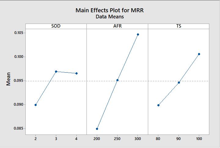
Figure 4: MaineffectsplotforMRR
Figure 4 represents the influence of various parameters on MRR. It can be observed that Traverse speed increases the MRR. This is due to an increase in intermolecular forces and energy causing the sharing and erosion of more material from the parent material. As the number of abrasives increase with an increase in Abrasive flow rate, the number of sharp edges performing the cutting action increases, resulting in higher MRR. An increase in Stand off distance also enables higher MRR due to the divergenceofthejetbecausethejetdiameterincreases due to divergence, which leads to the erosion of materialfromlargerareas.
Figure 5: SurfacePlotofMRRvsAFR,SOD
Figure-6: SurfacePlotofMRRvsTS,SOD
Figure 7: SurfacePlotofMRRvsTS,AFR
International Research Journal of Engineering and Technology (IRJET) e ISSN: 2395 0056
Volume: 09 Issue: 07 | July 2022 www.irjet.net p ISSN: 2395 0072


3.2.1 Main effects plot for Kerf width

Figure 9: ContourPlotofMRRvsTS,SOD
Figure 11: MaineffectsplotforKerfWidth
Figure 11 shows the main effect plot of MRR at different parameterslike, Standoff distance,Abrasive flow rateand Traverse speed in Abrasive water jet machining of Inconel718 material. It can be observed that Traverse speed increasesthekerfwidth.Itcanbehighlighted that when Abrasive flow rate is increased from 200 to300g/min,itdecreasesthekerfwidth.


3.2.2 Surface Plot and Contour Plot of Kerf width
Figure-12: SurfacePlotofkerfwidthvsAFR,SOD
Figure 10: ContourPlotofMRRvsTS,AFR
International Research Journal of Engineering and Technology (IRJET) e ISSN: 2395 0056
Volume: 09 Issue: 07 | July 2022 www.irjet.net p ISSN: 2395 0072
3.3

Figure 17: ContourPlotofkerfwidthvsTS,AFR


3.3.1 Main effects plot for Kerf taper angle


Figure 18: MaineffectsplotforKerf
Thekerftaperangleisameasureofthestraightnessofthe machined slot cross section. The main effect plot of the kerf taper angle as shown in Figure indicated a positive correlation between TS and the Kerf taper angle. Increasing the TS increases the kerf taper angle. This can beattributedtoinsufficientbroadeningofthebottomkerf width by the jet as TS increases. The increase in SOD was foundtoincreasethetaperangle.Thiscanbeattributedto the fact that at higher SOD, the jet is impacted by the flaring mode. Thus, eroding more material at the top causes a higher top kerf width and lower bottom kerf width. As Abrasive flow rate increases, the number of sharp edges performing the cutting action increases, resultinginlowerkerftaperangle.


International Research Journal of Engineering and Technology (IRJET) e ISSN: 2395 0056
Volume: 09 Issue: 07 | July 2022 www.irjet.net p ISSN: 2395 0072
From optimization plot Figure 6.13 the optimized parametric values and the ranges of optimization are SOD (2mm),AFR(300g/min)anTS(100mm/min).
Figure 25: Optimizationplotshowsoptimizedvaluesof parameters
The present study investigated the effect of AWJM parameters Stand off distance, Abrasive flow rate and Traverse speed on responsesof MRR,Kerf widthand the KerftaperangleforINCONEL718.Basedonthework,the followingimportantconclusionscanbedrawn:
Mathematical regression models were generated usingtheRSMtechnique,andANOVAresultshave showntheadequacyofthedevelopedmodels.
From the investigations carried out and reported in this thesis, a few possible future avenues of research derived fromthisworkcanbesuggested.

Normal probability, the significance of model terms, and the insignificance of lack of fit for all responseshighlightedgoodpredictioncapabilities of the developed models of MRR, Kerf width and thekerftaperangle.
Single objective optimization results yielded a maximumMRRof0.11003g/s(atSODof2.56566 mm,AFRof300g/min,andTSof100mm/min),a minimum Kerf width of 0.3173 mm (at SOD of 2 mm, AFR of 300 g/min, and TS of 92.7273 mm/min), a minimum Kerf taper angle of 1.1364 θ(◦ ) (atSODof2mm,AFR of300g/min,and TS of 92.7273mm/min).
Asimilarstudycanbedoneondifferentmaterials, composite materials and different material thickness.
A similar study can be done on the other process parameters which are not covered in this study for investigating effect on response parameters like water pressure, Orifice Diameter, Focusing TubeDiameter,Abrasiveparticlesizeetc.
UsedifferentDesignOfExperimenttechniquesfor planning of experiments such as Taguchi, Central CompositeDesign(CCD),FullFactorialetc.
Itismyproudprivilegeanddutytoacknowledgethekind of help and guidance received from my research supervisor Mrs. Sheetal S. Soni in preparation of this research work. I consider myself privileged to express gratitude and respect towards my research supervisor who guided me through the completion of the entire research work. I would also like to extend my thanks to the technicians of the BALAJI Enterprise for their help in offering me the resources to complete the experiment. I would like to thank my parents for helping me out and alsoforinspiringandmotivatingmethroughoutmywork.
[1]https://mechanicalenotes.com/abrasive water jet machining/
[2] Lingaraj N., Gajendran S, “ Study of optimization of abrasive water jet machining ,” Int. J. Appl. Eng. Technol., vol.6,no.1,pp.16 22,2016.
[3] D. S. Reddy, a S. Kumar, and M. S. Rao, “Parametric Optimization of Abrasive Water Jet Machining of Inconel 800H Using Taguchi Methodology,” Univers. J. Mech. Eng., vol.2,no.5,pp.158 162,2014.
[4] Karkalos, N.E.; Karmiris Obratan´ski, P.; Kudelski, R.; Markopoulos, A.P. Experimental Study on the Sustainability Assessment of AWJ Machining of Ti 6Al 4V Using Glass Beads Abrasive Particles. Sustainability 2021, 13,8917.
[5] Natarajan, Y.; Murugesan, P.K.; Mohan, M.; Khan, S.A.L.A. Abrasive Water Jet Machining process: A state of artofreview.J.Manuf.Process.2020,49,pp.271 322.
International Research Journal of Engineering and Technology (IRJET) e ISSN: 2395 0056 Volume: 09 Issue: 07 | July 2022 www.irjet.net p ISSN: 2395 0072
[6] Saravanan, S.; Vijayan, V.; Suthahar, S.J.; Balan, A.; Sankar, S.; Ravichandran, M. A review on recent progressesinmachiningmethodsbasedonabrasivewater jetmachining.Mater.TodayProc.2020,21,pp.116 122
[7] Thakur, R.; Singh, K. Experimental investigation and optimization of abrasive water jet machining parameter on multi walled carbon nanotube doped epoxy/carbon laminate.Measurement2020,164,108093.
[8] Alberdi, A.; Rivero, A.; De Lacalle, L.L.; Etxeberria, I.; Suárez, A. Effect of process parameter on the kerf geometry in abrasive water jet milling. Int. J. Adv. Manuf. Technol.2010,51,pp.467 480.
[9] Alberdi, A.; Rivero, A.; López de Lacalle, L. Experimental study of the slot overlapping and tool path variation effect in abrasive waterjet milling. J. Manuf. Sci. Eng.2011,133,034502.
[10] Alberdi, A.; Rivero, A.; De Lacalle, L.L.; Etxeberria, I.; Suárez, A. Effect of process parameter on the kerf geometry in abrasive water jet milling. Int. J. Adv. Manuf. Technol.2010,51,pp.467 480.
[11]Deaconescu,A.;Deaconescu,T.ResponseSurfaceMethod sUsedforOptimizationofAbrasiveWaterjetMachiningoftheS tainlessSteelX2CrNiMo17 12 2.Materials2021,14,247
[12] B. Satyanarayana and G. Srikar, “Optimization of Abrasive Water Jet Machining Process Parameters Using Taguchi Grey Relational Analysis ( Tgra ),” procedding 13thInt.Conf.pune,pp.1 6,2014.
[13] Reddy, P.V.; Kumar, G.S.; Kumar, V.S. Multi response OptimizationinMachiningInconel 625byAbrasiveWater JetMachiningProcessUsingWASPASandMOORA.Arab.J. Sci.Eng.2020,45,pp.9843 9857
[14] Z. Jurkovic, M. Perinic, S. Maricic, M. Sekulic, and N. Sad, “Application of modelling and optimization methods in abrasive water jet machining,” J. trends Dev. Mach. Assoc.Technol.,vol.16,no.1,pp.59 62,2012.
[15] F. Kolahan and a H. Khajavi, “Modeling and Optimization of Abrasive Waterjet Parameters using Regression Analysis,” World Acad. Sci. Eng. Technol., vol. 59,pp.488 493,2009.
[16]P.K.H.Thakkar,P.V.M.Prajapati,andP.S.aThakkar, “AMachinabilityStudyofMildSteelusingAbrasiveWater JetMachiningTechnology,”Int.J.Eng.Res.Appl.,vol.3,no. 3,pp.1063 1066,2013.
[17] G. Upadhyay and K. Hassan, “Optimization MRR Of Stainless Steel 403 In Abrasive Water Jet Machining UsingAnova And Taguchi Method,” Int. J. Eng. ressearch Appl.,vol.5,no.5part 2,pp.86 91,2015.
[18] M. Uthayakumar and V. A. M. Kathiresan, “Experimental invstigation of the process parameters in abrasive water jet cutting of red mud reinforced banana/ polysterhybridcomposite",DepartmentofMechanical
[19]J.aPatelandA.K.Gothwal,“OptimizationofAbrasive Water Jet Machining Process Parameters Using Particle Swarm Optimization,” Int. J. Mech. Ind. Technol. ISSN, vol. 3,no.1,pp.2348 759394,2015.
[20] M. A. Azmir, A.K. Ahsan, “Optimization of Abrasive WaterjetMachiningProcessParametersUsingOrthogonal ArraywithGreyRelationalAnalysis,”Reg.Conf.Eng.Math. Mech.Manuf.Archit.(EM3ARC)2007,pp.21 30,2007.
[21]O.Çolak,“Investigationonmachiningperformanceof Inconel718underhighpressurecoolingconditions,”Stroj. Vestnik/Journal Mech. Eng., vol. 58, no. 11, pp. 683 690, 2012.
[22] Vinod B Patel & Prof. V. A. Patel (2012), “Parametric analysisofabrasiveswaterjetmachiningofEN8material”, International Journal of Engineering Research and applications,2,pp 3029 3032
[23] Pravin R. Kubade, Pranav Potdar, Ravindranath G. Kshirsagar“ParametricOptimizationofAbrasiveWaterJet MachiningofInconel718material”,InternationalResearch Journal of Engineering and Technology (IRJET), Volume: 03Issue:08|Aug 2016
[24] Palleda, Mahabalesh. "A study of taper angles and material removal rates of drilled holes in the abrasive water jet machining process." Journal of materials processingtechnology,Vol.189,No.1(2007):pp.292 295.
[25] Fowler, G., P. H. Shipway, and I. R. Pashby. "Abrasive water jet controlled depth milling of Ti6Al4V alloy an investigation of the role of jet workpiece traverse speed and abrasive grit size on the characteristics of the milled material." Journal of materials processing technology Vol.161,No.3(2005):pp.407 414.
2022, IRJET | Impact Factor value: 7.529 | ISO 9001:2008 Certified Journal |