International Research Journal of Engineering and Technology (IRJET) e-ISSN: 2395-0056
Volume: 09 Issue: 07 | July 2022 www.irjet.net p-ISSN: 2395-0072

International Research Journal of Engineering and Technology (IRJET) e-ISSN: 2395-0056
Volume: 09 Issue: 07 | July 2022 www.irjet.net p-ISSN: 2395-0072
Department
Abstract The project activity introduces a wireless battery charging system with a charging device. The proposed method transmits power without any physical connection between the transmitter and the receiver side. The AVR family microcontroller’s (ATMEGA328P) which are used for proposed system constantly measures the charge on the battery and charges the battery accordingly this whole process is automated by microcontroller. The charge of the battery is displayed on the LCD screen (Voltage). As soon as the battery is fully charged, the microcontroller triggers switch off action andthe supply are cuttedout. Anelectronic ballast circuit is used in the project to scale down the grid's 230V, 50Hz AC supply to 12V AC (50Hz). An air core transformer's primary coil receives the transformed output. As current flows through primary coil, the magnetic induction process causes an EMF to be induced in the secondary coil. The transformer's secondary coil produces 12V of high frequency. Power is passed from the primary coil to the secondary coil, which are spaced apart by 2 4 cm. By enlarging the coil, the range may be extended. An Avr family microcontroller receives the secondary coil's output. This microcontroller keeps track of the battery's charge in real time, automatically charges the battery until it is fully charged, at which point it stops being charged. This charger may be used to charge and test the charge of batteries for a variety of gadgets and applications, including battery powered scooters and electrical vehicles.
Key Words: WPT (Wireless Power Transfer), Wireless Communication, Wireless Charging System with Charging Monitor, Wireless Energy Transfer.
Wireless battery charger can be used in many battery powered products likely smart watches, smartphones, andahostofothersmallelectronicproducts.Originally the technology focused at small products. Now a days wireless charging technology is used for larger applications which include cars batteries and many other items. Wireless charging usually works on principal of power transmission from one circuit to another via inductive coupling between two circuits. Sincenoelectricalconnectiondirectlyisimplementedit is very easy and does not depend on contacts that may
wear out and become unreliable after many charging cycles.
Wireless battery charging works by transferring electricity between two objects, often coils, using the magneticinductionormagneticfieldprinciple.Poweris transmitted without a physical connection being made from a source to a receiver, where it is frequently utilised to recharge a device's battery. With so many portable gadgets like smartphones, smartwatches, media players, and other portable devices, wireless charging is advantageous. However, they are widely used in items like electric toothbrushes when wireless functioning is necessary and transmission could be inefficientorfleeting.
Theflatshapeofthetransformerutilisedinthismanner makesiteasiertoaccesstheequipmenttobeemployed. Many wireless battery charging options are used when purchasingsmallitems. Thetransformer'ssecondaryis linked to the driving circuit, while the main side is connectedtothe230VACmainssupply,whichservesas themotherinower'stypicalpowersource.
Typically,thewirelessbatterychargingmechanismwill include two flat coils to accommodate the majority of circumstancesanduserapplications.Usually,thecentre of the pad or mat where the charging device is to be positioned is where the power supply is located. There are a few key points associated with wireless transmission receiver system. Factors such as efficiency, range of coils, frequency waves and the like affect the way wireless charging works. Another aspect of wireless charging that needs to be carefully maintained during design is to check and ensure that wireless power transfer’s transmitting circuit and its frequency must not affect or interfere with other electrical appliances and circuitry of outside world in theproperty,specificallythosewhoreceiveitspower.
Insteadofutilisingtraditionalcopperwiresandcurrent connections,thisprojectmeasuresbatterychargeandis a wireless power transfer instrument. Additionally, it uses a wireless communication method to fully charge thebattery.NikolasTesladevelopedtheideaofwireless communication. This power is designed to transport just a tiny quantity, such as to recharge batteries and other devices. We have a wirelessly powered
© 2022, IRJET | Impact Factor value: 7.529 | ISO 9001:2008 Certified Journal | Page916
 Pearl Patel1 , Dr. Dhananjay Upasani2 , Dr. Reena Gunjan3 Dr. V. V. Shete4
of Electronics and Communication Engineering, MIT School of Engineering, MIT ADT University, Pune, India
rechargeable battery for display reasons. This requires anelectricalconnectiontoconvertAC230V50HztoAC 12Vhighfrequencybeforebeingconnectedtothemain aircoretransformercoil.
Amaximumfrequencyof12Visproducedbythesecond transformer coil. Additionally, the system gauges battery charge and fully charges it. To do this, we employ a tiny AVR controller from the AVR family, which continuously monitors the battery charge, until thebatteryisfullycharged, atwhichpointthecharging process is stopped. Consequently, the energy is transmitted in this manner via the first coil to the secondcoilafterbeingseparatedbyadistanceofabout 1 cm. By expanding the coil's size, width may be increased.[fig.1]
The batteries for a number of equipment and applicationsmaybechargedwiththisproject,including motorbikes that charge the battery and unconnected vehiclesthatcanonlychargetoacertainextent.

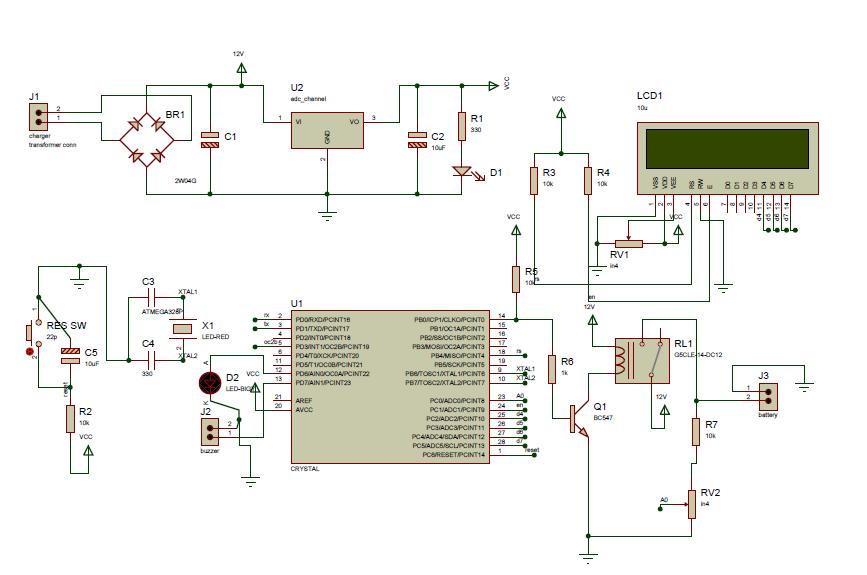
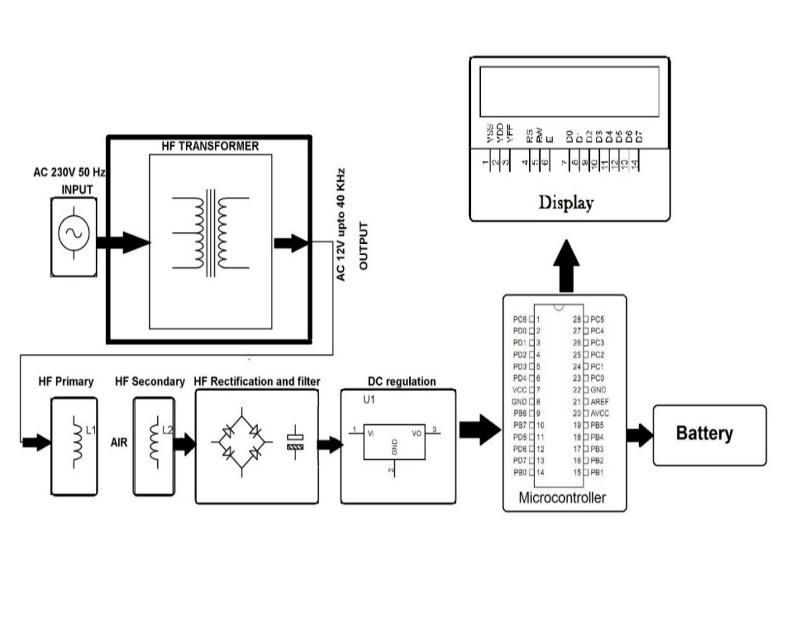
Figure.1BlockCircuitDiagram
Figure.2SchematicDiagram[9]
The output of transformer (Step downed AC) is connected to bridge rectifier where the bridge rectifier is rectifying the output and the frequency is getting doubledaspeaksofthenegativesidesareshifteddueto the bridge rectifier and hence we get our output as undirected one. This output is passed through the capacitor C which smooth out the DC output and removesACcomponentfromthesystemifanypresent. Further this smoothened output is connected to input pin of Voltage regulator IC (7805) which gives the constantoutputof5Vdespiteanychangeorfluctuations in input side of the circuitry. again, a capacitor is connected at output of voltage regulator IC (7805) to avoid sudden change in output making sure that it will give its rated output which can drive the dependant further circuitry of microcontroller and sensors of circuit.
The bias in Fig.1, Fig.2 is spontaneous which means we cannot say that if any coil finds bias. Therefore, the secondcoilgeneratesA.Casaresultofthecurrentflow in the primary coil throughout both halves of the cycle. The frequency of A.C is 25 KHz due to the quick switching of transistors. This has copper L1 windows thatarelinkedtothesecondtransformer.EMFfromL1 sends25KHzA.C.toL2(TransformerSystem).[Fig.2]
The bridge rectifier, which produces pulse setting DC and filters the voltage driven L2 coil through an electrolytic capacitor of around 1000 uF, is made up of four diodes. The capacitor's fully filtered output is sent toICLM7805,whichoutputsaconstant5voltsonPIN3 regardlessoftheinputdc(LM7805'sratingrangesfrom 9to14volts).[Fig.2]
The5VDCoutputofLM7805isalsofilteredwithasmall 10uF electrolytic capacitor for avoiding any circuit
generated noise and sudden change in output that can be used to drive next circuitry . one LED is connected aftercapacitorofLM7805whichshowstheindicationof powerisonoroffforcircuitry.Andotherwindingofthe transformer is used for battery charging which deals withhighervoltages.
The reaction converter's size, density, and end time of the ferrite core flux, as well as the frequency of oscillation, are all heavily influenced by these factors. Thecurrentintheresponsetransformergrowsafterthe cycle has started until the spine is full. At this moment, the active transistors' reaction drive is turned off, and after its expiry date, it turns off. The oscillation frequency in this application is around 25 kHz. Dependence on storage time weakens the transistor's RC network, which accelerates the rate of discharge from the base when the transistor is turned off. The network also strives to stop the device's artificial opening by separating the base from the roaming that thebasetransformercauseswhenitturnsoff.
To have storage durations within predetermined ranges,thetransistorsandFETsmustbechosen,tested, and selected. Larger storage time transistors can lead the circuit to wash below the output converter's operational thresholds, resulting in complete filling at theconclusionofeachcycle.Asaresult,thetransistors' collectorcurrentwillsurgethroughoutthecycle,which willeventuallyleadtooverheatinganddestruction.

In previous chapter we see that the battery charges wireless without using wires (copper cables) and it charges battery up to 100% capacity by using Microcontroller from the AVR family, which continuouslymonitorsbatterychargingandchargesthe battery until it is fully charged. could block the battery fromcharging.
Inthischapterfocusesonthemagneticfieldlayoutofa multiple coil transmission power transfer system for rechargingelectriccarswithaminimalairgapbetween thetransmissioncoilsandthereceiver.Forsimplicityof useanda superioruser experience,thistechnologyhas several potential uses, ranging from tiny toothbrushes topowerfulelectriccars.
There are already various smart wireless battery chargerunitsinthemarket.TheSmartWirelessBattery ChargingProjectcomeswithtwounits,oneofwhichisa wireless power source that is last receiving unit that converts usable energy. This power is used in this project to charge a 12V battery charged by the ATmega328 system and is disconnected as soon as the requiredpowerisreached.Itallstartsattheendofthe
transfer.Here,powerfromthesupplyoflargepipelines is taken and reduced to AC 12V at a frequency of 38 KHz. Because air loss is so low at high frequencies, this high frequency is necessary. The circuit inside the high frequency transformer handles frequency reduction on itsown.
Thenasecondcoiloutofthetransformertransmitsthis energy in the form of electric waves. The receiver coil whenplacedwithinthelimitsofreceivingtheseenergy waves converts back the electromagnetic waves into electrical signals. In this way the receiver board gets powered up to run the micro controller system as well as for charging the batteries. Battery charge is monitored from time to time to see if the desired voltage has been reached. For the purpose of studying analogy energy, these analogy energies are converted into digital values and returned to the percentage that will be displayed on the LCD screen. When charging is complete, the relay switches on and disconnects the batterysupplyuntilthebatteryvoltagedropsbelowthe desiredvoltage.Whencharging,itindicatesitscharging and charging percentage and notifies you when chargingiscomplete.
AhmedA.S.MohamedandChr.Joffe[1 3]presentedthe magnetic field configuration of the Inductive Power TransmissionSystem(IPT)forusinganarrowairgapto charge electric cars the transmission coils and the receiver. The placement of a particular vehicle package utilising a new integrated numerical approach and processing of other geometric coils and other twisted structures improve the magnetic design of a multi coil system.
Razvan asanache and Isaac Nam [4 5] the result is a wireless charger with a few desirable features: eliminates the need for digital communication between the transmitter and receiver, the design is strong against coefficient of integration and load variability, operatesmostofthetimeinahighlyefficient(cohesive) operating environment. gain frequency), uses synchronized adjustments to improve efficiency, does not require a lower battery charge controller, and providesfasterchargingperformancemode.
ThepaperpresentbyD.Kurschner[7]awirelessPower Transfer (WPT) uses magnetic resonance, a technology that can free a person from irritating cords. Currently various studies have been done and continue to increase the efficiency of wireless power transmission. ThisprojectinitiatedtheintroductionofWPTtocharge an electric car battery. In this study, the distance between the sender and receiver circuit has been improved, and at the same time the different power level at different distances between the sender and receiverhasbeenassessed.
Volume: 09 Issue: 07 | July 2022 www.irjet.net p ISSN: 2395 0072

In order to analyse the wireless charging process, the WPTS (Wireless Power Transfer System) is built. Using thetechnologythatisnowinuseasthestateoftheart, preliminary study was done on the fundamentals of wirelesspowertransferapplications.Basedonphysical and strength criteria, the Resonant Inductive Power Transfer (RIPT) charging system is chosen as the best candidatemodel.
Pedro Lopes [9] studied RIPT control is recommended aswell power(electrical)converter rating and damages the networks. Synonyms for results are available, also made to measure, is the indication. The suggested topologyandcontrol areverifiedby testing.Analysisof theobservedwavesleadstoaconclusionontheoverall effectivenessoftheinductiveresonantcharger.
A novel method for electric car wireless charging that uses the battery chargers to demonstrate the theory thathasbeencreated.Electriccarbatterychargingwith a charger and cable is time consuming, costly, and unsafe. Vehicles with fuel and petrol powered vehicles now on the road contribute to air, noise, and greenhousegaspollution.
ShitalR.Khutwad [8]thisstudydescribestheinductive coupling method based wireless battery charging system that has been used for electric vehicles. The driving loop, which uses a MOSFET for switching, is utilised between the transmitter coil and the reception coil. When the vehicle is present or not, you may turn thetransmittercoilcircuit ONor OFF,correspondingly. The system provides safety, dependability, simple to maintain, and an extended product life while operating ata67percentefficiencylevel.[8]
Wireless transmission, another name for wireless charging, is a technique that enables a power source to transmitmagneticenergytoanelectricalloadintheair withouttheuseofcords.Duetoitssimplicityofuseand improveduserexperience,thistechnologydrawsawide range of applications, from low power toothbrushes to more potent electric automobiles. Today, wireless charging is quickly evolving from futuristic concepts to a technology found in many commercial items, particularlysmartphonesandothersmartgadgets.
XiaoLu[10]studiedanew generationsmartphonewith integrated wireless charging capabilities started to be released in 2014 by a number of top smartphone makers. According to IMS Research, the market for wireless charging will be worth $4.5 billion in 2016. According to Pike Research, the market for mobile phone devices is expected to quadruple to $ 15 billion by2020.
Arigorous processofregionallevelanalysisanddesign ofallsystems,developedto forthefirsttime,basedon the introduction of a two hole parallel circuit, to define a wireless power connector where the transmitter and receiver are in the middle of a nearby field or in an equally distant region. This method allows one to accuratelycalculatethevalueofaqualifyingsystem,i.e. theefficiencyofthepowertransfer.
A. Costanzo et al [11] the detailed examination of specificdualconfigurationguidelinesisfollowedbythe adoption of software tools based on a mix of complete wave analysis and indirect harmonic balancing methods. A few real world examples based on this design method are provided to show the testing and predicted behaviour of anomalous devices for both close byandfar offpowertransmission.
J. Garnica [12] Since the early 20th century till the present,wirelesspowerhasbeenahotissue.Thisstudy explores radiant energy utilising microwaves and follows the development of wireless energy transmission from Nikola Tesla. This study discusses the distinctions between near field approaches and remoteregions,explainswhythenear fieldapproachis more appropriate for consumer electronics, and investigates close by energy transfer using magnetic field. Examples of wireless power systems for short andmedium termuseareinvestigated.
Power is suggested to be sent one way to a greater operationalareautilisingtheuniqueconceptofwireless power transmission via inductive coupling. This idea makes use of a zigzag group that was specifically created on the transmission side to create a moving magnetic field. This field's reception coefficient is affectedbymagneticfluctuations,whichfeedspowerto thecoil.
J. Gao [13] the prototype system offers one or more power receivers that are 4.0 mm thick and 11.5 mm broadaneffectiveworkingareaof180by220mm.Each receivergetsa staticpower ofaround330mWat 3.1+ 0.4 V dc, which is electrically driven throughout the working system. This idea may be applied to enable offlinemicrorobots.
Since its introduction by Nikola Tesla in 1900, the concept of wireless power beams, lasers and mutual magnetic induction. Far field systems such as lasers, focused microwaves and large aperture RF links are well suited for traversing large (>100 m) distances but exhibitrelativelylow(<10%)overallsystemefficiencies due to beam diffraction limits, atmospheric absorption andmultipleconversionlosses.Near fielddevicesusing direct or resonant magnetic induction offer higher
Volume: 09 Issue: 07 | July 2022 www.irjet.net p ISSN: 2395 0072

efficiencies but only at low power levels and close distances.
G.E.LeyhandM.D.Kennan[14]thispaperexploresthe potential of using coupled electric fields between two tuned resonant transformers as a means for transmitting considerable power (>500 W) over laboratory scale distances (5 to 20 m) with reasonable efficiency. The paper presents design concepts, circuit simulationsandtestresults.
In previous chapter we observe that wireless power transmission and reception has attracted interest since the early20thcenturytill thepresent day.SinceNikola Teslafirstproposedtheideaofwirelesspowertransfer in1900,ithasevolvedinavarietyofways.
In this chapter we do (1) a continuous test which is an electricalcircuittesttodeterminethecurrentflow(that is actuallya complete circuit). (2) the power of the test performedtocheck whethertheelectrical powerin the variousterminalscomplieswiththerequirementornot. Mobile phone and cordless appliance charging are no longer necessary with the use of cables. By merely positioning the appliance close to a wireless power transmitteroranauthorisedchargingstation,awireless charger allows the battery inside any battery powered equipment to be charged. As a consequence, the appliance enclosure can be completely sealed. In addition to the inherent convenience it provides, wireless charging may also significantly increase dependability because the side mounted charging port on an appliance is susceptible to mechanical damage and can even be accidentally plugged in with the incorrect adaptor. Wireless charging is based on the well known Faraday's law of induced voltage, which is frequentlyappliedinmotorsandtransformers.
The contactless Inductive Power Transfer (IPT) allows electrical energy to be transferred to both stationary and mobile consumers without the use of physical connections, wires, or slip rings. A new systematic and modular design technique must be used in order to reduce the increased development effort of modern contactless inductive power supply. These methodologies, which are specifically integrated into a simulation software tool, incorporate novel techniques to improve the transfer efficiency and placement flexibilityoftheconsumerdevice.
The coil and ferrite geometry can be optimised to increasepositioningtolerance.Inthisway,theeffectsof modifyingphysicalandgeometricalfactors onmagnetic coupling and therefore on electrical transmission are
examined.AnovelIPTsystemforhomeapplianceswith an output power range of 1 kW is given as a consequence of the design technique, with an overall efficiency of more than 90% and a high positioning tolerance.

In above Fig.3 It depicts the input of a 6 12 V direct current source delivered by a battery or eliminator to the electronic ballast. Inside an electronic ballast, a technique called inversion converts DC signals into AC signals. They are seldom encountered. The electronic ballast's transistor switching action high frequency AC signals from low frequency AC signals are produced. The transmitting coil uses AC impulses with a high frequency received from an electronic ballast's input. Receiving Coil produces an EMF as a result of Magnetic Induction and Resonance.TheCellPhoneChargerCircuit receives its input from the Receiving Coil's output. Therefore, wireless power transfer enables cell phone charging.
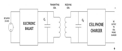
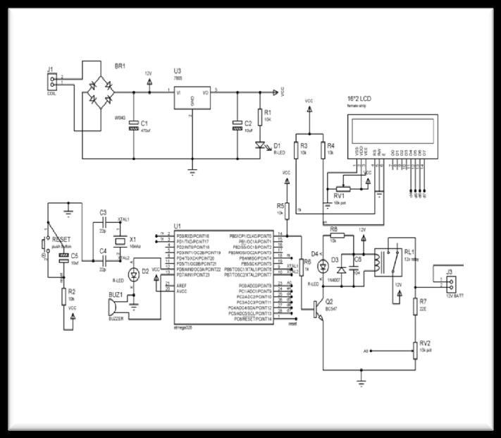
Figure.4 FullcircuitDiagram


Generally,light batterychargers do not offer the ability to charge other’s battery technology or batteries with the same condition but with less or more voltages and power. Best of all, this may result the battery uncharged. Worse still, it could be a serious security risk. A micro controller can produce the wisdom to solvetheseproblems.Inadditiontointelligentcontrols, the micro controller can provide flexible solution, an inexpensiveforchargingbatteries.

The battery charging applications can be modified quickly by using a small controller. With this the serial communicationcapacityofthesub controller,real time data monitoring and logging is possible. Simple battery chargers use all parts of the simulation to accomplish their mission. However, with the help of a micro controller, a charger can be made smarter. The advantages of Micro controller are flexibility to handle various technologies, electrical power and flexibility Voltage Generation Controller, Multiple Charging / Output Battery Packs, “Windowed” A / D Advanced Adjustment. The micro controller gives the design flexibility. Modification may be accomplished using software not the hardware, and charging methods can be readily made helpful to fit the user’s individual battery charger packs. The capacity or ability to rechargeanddischargeasinglebatteryortwobatteries ofthesametypemeangreaterflexibility.
There are a number of well known families of small controls used in different systems according to their capabilities and their ability to bring about the desired function, the most common of which are 8051
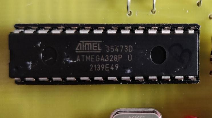
microcontrollers, AVR and PIC. In this project, the AVR family of microcontrollers are introduced. AVR was founded in 1996 by Atmel Corporation. AVR buildings were created by Alf Egil Bogen and Vegard Wollan. A low power, 8 bit CMOS microcontroller based on the AVRimprovedRISCarchitecture,theAtmelATmega328 can carry out complex instructions in just one clock cycle.
There is a 1 KB Electrically Erasable Programmable Read OnlyMemoryonthe ATmega328(EEPROM).This feature demonstrates that the microcontroller can still store data and provide outcomes after receiving an electric source, even if the electric supply is disconnected. Additionally, the ATmega 328 features 2KB of static random access memory (SRAM). Later explanationswillincludeothertraits.
Themostwell likedproductonthemarketrightnowis the ATmega 328, which offers a variety of unique characteristics. A real time counter with a separate oscillator,sixPWMpins,aprogrammableSerialUSART, a programming lock for software security, throughput of up to 20 MIPS, and high performance are a few of thesefeatures.TheATmega328willbecoveredinmore detailinalaterportionofthisarticle.
As indicated in the beginning, Harvard architecture whichincludesprogrammememoryandaseparatedata memory isthefoundationuponwhichATmegamicro controllers are built. Flash Random Access Memory, commonly referred to as Program Memory or Code Memory (ROM). Program memory can be between 8K and 128K bytes in size. 32 General Purpose Registers, Input/output Memory, and Internal Static Random Access Memory make up the three sections of the data memory (SRAM). The size of internal SRAM and I/O Memory differs amongst chips, although the size of General PurposeRegistersisfixed.
ThefollowingcharacteristicsareprovidedbytheAtmel ATmega48/88/328: A 6 channel 10 bit rADC (8 channels in TQFP and QFN/MLF packages), a programmable Watchdog timer with inter process communication, a byte oriented 2 wire Serial Interface, an SPI serial port, a serial programmable USART, 256/512/512 bytes of EEPROM, 512/1K/1K bytes of SRAM, 23 general purpose I/O lines, 32 general purpose working registers, and three flexible Timer/Count.
A genuine read while writing self programming mechanism is supported by ATmega328 (SPM). You may use the SPM command from the separate Boot LoaderCategory,whichispresent.
The16KbytesofsystemstorageontheATmega328are located on the chip. Flash is configured as 8K 16 becauseAVRinstructionsareall16or32bitswide.The Flash Program memory area is divided into two sections, Boot Loader Phase and Phase, for the security ofthesoftware.ATmega328application
Thelocationofthepresentlyusedcommandisstoredin this programme counter register on a computer's CPU. The system for each, counter raises the value it has stored by 1. command that is downloaded. The applicationcalculatordirectsuserstothenext message inorderonceeachcommandhasbeendownloaded.The system calculator often resets to 0 when the machine restarts or resets. A programme on a computer is a predetermined set of operations that the machine carries out. A computer processor's software is called an instruction. An address in a computer refers to a unique spot in storage or memory. One of the few data archives used by the CPU is the register. The most crucial component of microcontrollers is the system counter.
They are the fastest AVR microcontroller that uses multiplecommandsinasingleoperatingcycle.PICsare about 4 times or slower than AVRs, using smaller amountofpowerandcanworkwithavarietyofenergy saving methods. Let's make a comparison between the threemostwidelyusedmicrocontrollerfamilies.
AVR is an 8 bit small controller owned by the RISC (Reduced Instruction Set Computer) family. In the RISC architecture a bunch are not only few in number but alsoeasytouseandquick toexecute.Anothercategory of classification is CISC (Complex Instruction Set Computers). To view the between differences CISC and RISC.Wewillinvestigatemoreonthisaswelearnmore
about the features of the AVR microcontroller in the sectionthatfollows.
The microcontroller has the ability of receiving and transmitting data that is eight bits wide. Eight bit I/O registers are readily available. The family of AVR controllers has a register based structure, which implies that each operation's datatypes and outcomes are kept in separate registers. An easy example of conducting an OR operation between two input registers and saving the result in an output register is showninthepreviouslymentionedfigure5,which.

1. TinyAVR Small in size and memory, only appropriateforapplicationbasics
2. MegaAVR The majority of them are ideal for medium and sophisticated applications, contain a lot of internal peripherals, and have good memorycapacity(upto256KB).
3. XmegaAVR Usedtopromotesophisticatedapps that demand fast processing and a lot of system memory.
AVR microcontrollers have 32 x 8 bit standard operationalregistersandarebuiltonanadvancedRISC architectural design. During one cycle of the clock, the AVR is able to input into two registers for general objectives and place it in the ALU to perform the requested function, and then return the result to the incomprehensibleregister.
ALUisabletoperformcalculationsandentriesbetween theregisterorfromtheregisterareperformedlogically in terms of consistency. Only one register tasks suchas takingacomplementcanalsobeperformedatALU.We note that the AVR does not have an accumulator like registerasinthe8051familyofmicrocontrollers;tasks can be performed between any registers and can be savedinanyofthem.
AVRfollowstheHarvardArchitectureformatwherethe processor is loaded with different memory and System basesandDatainformation.Herewhilethecommandis being performed fully, the following command is pre downloadedfromthesystemmemory.
Since AVR is capable of performing one cycle, it indicates thatAVRcanprocessamillioncommandsifa frequency of 1MHz is utilised. The controller's processing speed will increase with increasing operation frequency. We have to improve energy efficiency at processing speeds and we need to choose therightfrequencyforoperating.
There are two flavours of the Atmega16 microcontroller:
1. Atmega16: Operating frequency range is between0and16MHz
2. Atmega16L: Operating frequency range is between0and8MHz
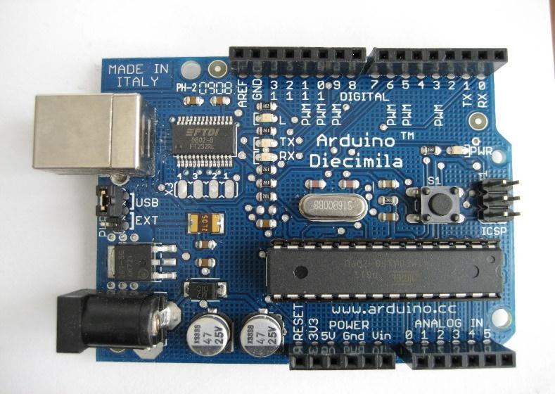
Arduino is an open source software and software company, project, and community of users who design and produce small single board controls and small control kits to build digital gadget. Different types of microprocessors and controllers are used in Arduino board designs. boards that may be attached to various expansion boards (also known as "shields") or veneer boards (making prototyping possible) and different circuits. These boards are equipped with digital anchor setsandoutput/input(O/I)symbols.
Programs can also be loaded onto boards with a network of ports, certain variations also including UniversalSerialBus(USB).Thecomputerprogramming languages C and C++, as well as a common API commonlyreferredtoastheArduinolanguage,whichis supported by the language of Processing and utilised with an altered rendition of the Processor IDE, can be appliedtomanageminorcontrols.
The project of Arduino started in 2005 as a student deviceattheItalianInstituteofInteractionDesignIvrea, it seeks to present novices and everyday users with a cheap and simple route to construct devices that function according to their requirements utilising actuatorsandsensors.Recreationalrobots,motion,and temperature detectors are typical examples of such gadgetsforbeginners.
The project's objective was to provide easy, affordable tools for non engineers to use while producing digital projects. The Wiring platform featured an ATmega128 microcontroller on a printed circuit board (PCB), a Processing based IDE, and library features for quick microcontrollerprogramming.
IDE (Integrated Development Environment) is a software program that given complete resources for computer programmers to develop software. The IDE usually made up of at least single source code editor, a dynamictoolbuilderandcorrector.Arelocationcontrol system or other tools that help with the creation of Graphical User Interface (GUI) may occasionally be incorporated, blurring the line between IDE and other components of the larger software development environment. For object based software development,

many contemporary IDEs additionally include a class browser,objectbrowser,andsectiondiagram.
ArduinoIDEisamulti platformimplementationwritten inJavaprogramminglanguage.ItcomesfromtheIDEof language processing and editing. It includes a code editorwithfeaturessuchascutandpastetext,replacing and searching text, auto loading, splint matching, and highlightingsyntaxandprovideseasyone clickwaysto merged and upload programs to the Arduino board. It alsocontainsamessagebox,atextrepair,atoolbarwith buttons for general functions and a menu of work menus.
TheArduinoIDEhasspecificcodeguidelinestosupport the C and C++ languages. Software from the Wiring project, which offers several installation and output operations, is included in the Arduino IDE. User coded programming only needs two fundamental operations, the main programme stub is connected to the main programme loop and the initial drawing () in a cyclic executive program via the GNU tool chain, embedded with IDE. distribution. Arduino IDE uses the program avrdude to convert usable code into a text file in hexadecimal text that is downloaded to the Arduino board via an uploader program on the firmware of the board.
The Arduino project offers an Integrated Development Environmentinadditiontotypicalcompilertool chains (IDE). Asa tool for students, the Arduino project began in2005 to providea low costandeasy wayfor novices and professionals to create devices that interact with their environment usingsensorsandactuators. Common examples of such devices intended for beginner hobbyists include simple robots, thermo statsandmotiondetectors.

The Arduino Pro IDE was made public. Next, in March 2021, IDE 2.0 was given as the new name for the beta test. Despite advancements including a more professional programming environment, autocompletionsupport,andGitintegration,thesystem continues to use the Arduino CLI (Command Line Interface).Thefrontendoftheprogrammeisbuiltusing the Eclipse Theia Open Source IDE. The following are theprimaryfeaturesofthelatestrelease:
Modern,wellequippedworkingenvironment,
ProMode,ClassicMode andDualMode,
NewBoardManager,
NewLibraryManager,
BoardList,
BasicAuto Completion,
SerialMonitor
In the Arduino IDE, a sketch is a written programme. The useable computer stores sketch the extension as text files "extension. ino." Pre 1.0 versions of the Arduino Software (IDE) stored sketches with the "extension.pde"format.Onlytwofunctionsarepresent inanArduinoC/C++programme:
setup(): This function is never used more than once when a sketch starts following a power on or reset. Using it, the sketch's variables, input and outputpinmodes,andothernecessarylibrariesare changed.Itisconnectedtotheprimarygoal().
loop(): The function loop()is continually executed in the main programme after the setup() method quits(ends).Untiltheboardisturnedofforreset,it is in control. It is comparable to the while(1) function.
In electronics, a continuous test checks an electrical circuitto seeifitisflowing current(thatitisactuallya complete circuit). Continuity testing is performed by setting a small voltage (series cable with LED or a component that produces sound like a speaker) throughout the selected path. The circuit is "open" if damaged components, broken conductors, or excessive resistanceareobstructingthepassageofelectrons.
Numerous current metres and specialised continuous testers cheap,straightforwarddevicesoften equipped with a simple light to monitor the current flow are
tools that may be used to conduct continuous tests. There won't be many inconsistencies between "right" conclusions, and only between "right" conclusions, therefore checking the string of strings' continuity to identify the two non single ends is a significant application.
As soon as the hardware soldering and setup are finished, this test is performed. This examination aims to find any open power lines in the circuit following a blackout.Inmanycases,thepowersupplyinthecircuit is lost due to improper adhesion, improper and improperhandlingofthePCB,improperuseofcoupling iron,partialfailureandthepresenceofinterruptionsin the circuit diagram. We use several meters to perform this test. We store several meters in buzzer mode and connect the ground terminal several meters down. We connectbothterminalstoapaththatneedstobetested. Ifthereisaconnectionyoucanhearabeepsound.
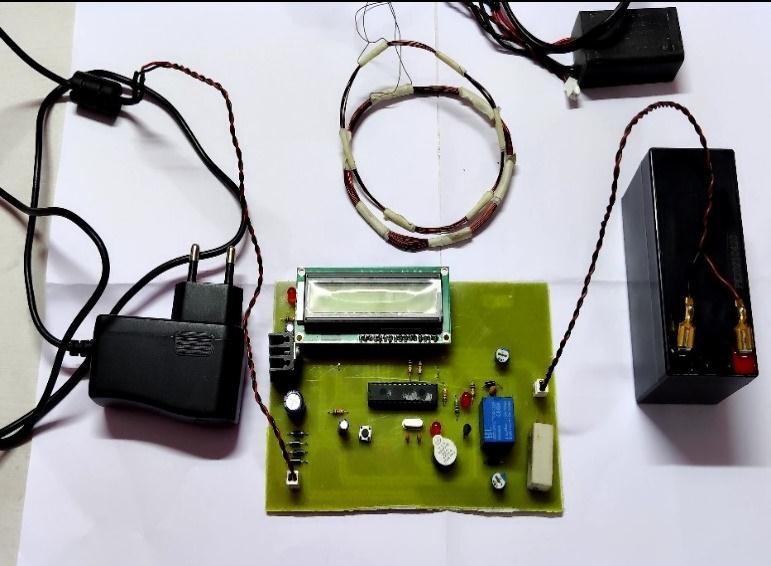
• High frequency transformer and wirelessly transforming power We are using coli which is high frequency transformer and wirelessly transforming power to the circuit through second coilattachedtothecircuit.
• LED screen monitoring When we supply power the circuit indicter starts glowing which indicate that power supply through coil to coil and the LED screenmonitorshowuschargingstatus.
• The fully charged battery As soon as the battery charged100%theLEDscreenshowsthestatus.The battery Fully charged and the circuit automatically switchoffthesupply.
This test is done to determine whether, the voltage of power at the different points complies with the necessary power or not. We take several meters and kept them in voltage mode. Remember that these tests are done without ICs. When employing a transformer, we must first verify that the transformer's output produces the necessary 12 V AC voltage (depending on thetransformerkeptinthecircuit). Whenthebatteryis in operation, we use a multi meter to determine if it is completely charged or not based on the battery's specifiedvoltage.
Then weapply this voltage to the power supply circuit. NotethatwedothistestwithoutICsbecauseifthereis toomuchelectrical power,this couldleadtodamageto ICs. If the circuit contains an electrical controller it checkstheinputtothepowercontroller(suchas7805, 7809,7815, 7915 etc.)that is,doesitgetthe12V input
and output required depending on the controller used inthecircuit.
This output from the power controller is supplied with thepowersupplypinofcertainICs.Therefore,wecheck the voltage level on those pins to see if we are getting therequired electricalpower.Similarly,wecheckother terminals for the required voltage. In this way we can ensure that the voltage across all terminals complies withtherequirement.
the Arduino board using the uploader programmer builtintothefirmwareoftheboard.
• Coding TheIDEcodeeditoriscalledanIntegrated Developmentsite.IDEisanapplicationforsoftware used to formatting your code, testing syntax, and usingandtestingyourcode.SomeIDEscanworkin multiple programmed language, while others are morespecificonlyinonelanguage.
Wireless Power Transmission Using Inductive coupling delivers various benefits over other choices,includingthefollowing:
Simple Design Both in principle and in practise, thedesignisnotdifficulttoimplement.Thebuilt in circuits are simple to put together and use a small numberofcomponents.
• ArduinoPlanningProject IntegratedDevelopment Centre (IDE), It was created using the Java programming language and is a cross platform application. It is built using the Language Processing IDE and Strings. It is intended to acquaint artists and other newcomers who are not familiar with software development with programmes.
• Sketch The Arduino IDE program is called a "sketch". It provides a code editor with tools like syntax highlighting, bracelet matching, and auto zoom, as well as a straightforward one click mechanism for integrating and uploading programmerstotheArduinoboard.
• Programming language When editing code, the Arduino IDE supports C and C++ utilizing certain rules. The wiring undertaking, which is an application library that comes using the Arduino IDE and provides a variety of standard installation andtechniquesforoutput.
• CompilingandLinking ThestandardArduinoC/C ++ diagram combines two functions that are integratedandlinkedtothemainstubofaprogram () in a functional cyclic executive system, connectingtoandusingtheGNUtoolchain,included with the Arduino IDE distribution. Uses the software to convert the usable code into a text file in hexadecimal format, which is then uploaded to
Lower Frequency Operation The technology operates in the kilohertz frequency band. Additionally, there is virtually little radiation dangerintheLF band.
Low Cost Theentiresystemisbuiltwithdistinct, easily accessible elements. The design didn't require any specialty or specially ordered parts. As aresult,wewereabletodrasticallycutthesystem's overallcost.
Practical for Short Distance

Volume: 09 Issue: 07 | July 2022 www.irjet.net p ISSN: 2395 0072 © 2022, IRJET | Impact Factor value: 7.529 | ISO 9001:2008 Certified Journal | Page925
As long as the coupling coefficient is optimised, the system is particularly useful at close range. The design also provides the flexibility to reduce the receiver size significantlyforpracticalapplications.
Wireless Power Transmission using Inductive coupling There are various drawbacks to this approachthatshouldbehighlighted.
High Power Loss The flux leakage is quite high becauseofitsmajorairdesigns.Lowefficiencyand excessive power loss are the effects of this. When used in conjunction with a logical system, weight loss might be slowed down by improving productivity.
1. If without the battery we start power supply to the circuit, then the LED screen show charging statusis,“Batterycharging0%charged”. Shown by arrow in below circuit (That battery is not connected)asshownFig.8.
Figure.8 Withoutbattery0%
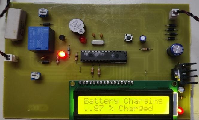
2. When we start battery charging the LED screen show charging status, “Battery charging” with percentage.AsshowninbelowLEDscreenFig.9
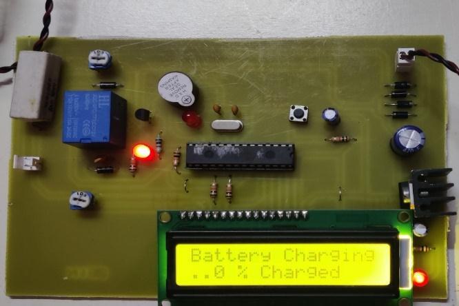

it uses maximum 1A current. Its rate of charging is 6W to 12W. Voltage across battery is 12.6V and maximum 14.4V depending on the distance betweenthecoils.
This project introduces a wireless battery charging circuit using a new method. The proposed method measuresanywirelessconnectionusingasimplecircuit to detect the flow of a transmitter coil, such as a DC value. This method does not require a high sample frequency to detect the voltage and power of the transmission coil. The proposed wireless battery charging circuit is used to charge the battery pack to control power outages and voltage. The model circuit for charging a 12 V battery pack is tested under a variety of load resistance conditions and coil steering conditions. The system Operates on 12V and wirelessly charges 13.2V to 17V battery. While system works it usesmaximum1Acurrent.Itsrateofchargingis6Wto 12W. Voltage across battery is 12.6V and maximum 14.4V depending on the distance between the coils. Subsequently all test and simulation results showed that the proposed method is well suited to control wirelessbatterychargingefficiently.
Figure.9 Batterycharged87%
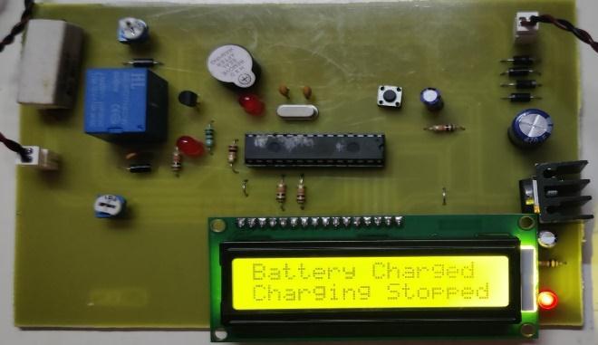
3. As the battery reaches 100% capacity the LED screen show the “Battery charging 100% Charged” and stop charging the battery. As showninFig.10
When we are use ATmega328 controller integrated circuit with programming in circuit. The address (position) of the presently used command is stored in the programme counter registers of a computer processor. The system counter increments its stored valueby1witheachcommandthatisdownloaded.The software calculator indicates the following message in the sequence after each command has been downloaded. The system calculator often resets to 0 after a computer restart or reset. A programme on a computer is a predetermined set of operations that the machinecarriesout.Acomputerprocessor'ssoftwareis called an instruction. An address is a unique place in memory or storage within a computer. One of the little archives used by the processor is the register. The system counter is the most important feature for microcontrollers.
Figure.10 FullyCharged100%
When we start supply to the circuit from mains supply it start charging battery as shown in above figures.ThesystemOperateson12Vandwirelessly charging13.2Vto17Vbattery.Whilesystemworks
When you go to the atmega328 system think of pin no. as the color setting on the previous PIN (as the control pinisadigitalinputoroutputpin).Usetheappropriate PIN to find the correct interface for the appropriate inputoftheanalogyinputshouldbesettotheoutputof the analogy pin must be set to the pins and the same digitalinputandoutput.
International Research Journal of Engineering and Technology (IRJET) e ISSN: 2395 0056

Volume: 09 Issue: 07 | July 2022 www.irjet.net p ISSN: 2395 0072
[1] Ahmed A. S. Mohamed, Dylan Day,Andrew Meintz,Myungsoo Jun, “Real Time Implementation of Smart Wireless Charging of On Demand Shuttle ServiceforDemandChargeMitigation”.IEEETrans. Veh.Technol.70(1):59 68(2021).
[2] Marino Coppola, Pasquale Cennamo, Adolfo Dannier, Diego Iannuzzi,Santolo Meo, “Wireless Power Transfer circuit for e bike battery charging system”. 2018 IEEE International Conference on Electrical Systems for Aircraft, Railway, Ship Propulsion and Road Vehicles & International Transportation Electrification Conference (ESARS ITEC),10.1109/esars itec.2018.8607342,2018.
[3] Chr.Joffe,A.Rosskopf,S.Ehrlich,Chr.Dobmeierand M. Marz, "Design and optimization of a multi coil system for inductive charging with small air gap".IEEE Applied Power Electronics Conference (APEC),pp.1741 1747,20 24March2016.
[4] Razvan asanache, Mihai iordache, Mihaela Cristina turcu, Alexandru grib, Lucian Vasile ene, Diana Ramona sanatescu, “Wireless Charging Systems for Electrical Vehicle Batteries”. 2020 12th InternationalConferenceonElectronics,Computers and Artificial Intelligence (ECAI), 10.1109/ECAI50035.2020.9223233,2020.
[5] Isaac Nam, Roger Dougal, and Enrico Santi, "Novel Control Approach to Improving Efficiency in Wireless Lithium Ion Battery Charging for Portable Electronics“.ECCE2012,pp2482 2491,Sep,2012.
[6] Kittisak Phaebua; Titipong Lertwiriyaprapa; ChuwongPhongcharoenpanich“Studyofarepeater Tx antenna concept of a portable device wireless battery charging system”., The 20th Asia Pacific Conference on Communication (APCC2014),Oct. 2014.
[7] D. Kurschner, C. Rathge and U. Jumar, "Design Methodology for High Efficient Inductive Power Transfer Systems with High Coil Positioning Flexibility", Industrial Electronics IEEE Transactions on,vol.60,no.1,pp.372 381,2013.
[8] Shital R. Khutwad,Shruti Gaur, “ Wireless charging system for electric vehicle” 2016 International Conference on Signal Processing, Communication, Power and Embedded System (SCOPES), 3 5 Oct. 2016.
[9] Pedro Lopes;Pedro Costa;Sónia Pinto ” Wireless Power Transfer System For Electric Vehicle Charging”, 2021 International Young Engineers Forum(YEF ECE), 9 9July2021.
[10] Xiao Lu,Ping Wang,Dusit Niyato,Dong In Kim;Zhu Han, “ Wireless Charging Technologies: Fundamentals, Standards, and Network Applications”, IEEE Communications Surveys & Tutorials(Volume: 18,Issue: 2, Second quarter 2016),11November2015.
[11] A. Costanzo et al., "Electromagnetic energy harvesting and wireless power transmission: A unified approach", Proc. IEEE, vol. 102, no. 11, pp. 1692 1711,Nov.2014.
[12] J. Garnica, R. A. Chinga and J. Lin, "Wireless power transmission: From far field to near field", Proc. IEEE,vol.101,no.6,pp.1321 1331,Jun. 2013.
[13] J. Gao, "Traveling magnetic field for homogeneous wireless power transmission", IEEE Trans. Power Del., vol. 22, no. 1, pp. 507 514, Jan. 2007.
[14]G. E. Leyh and M. D. Kennan, "Efficient wireless transmission of power using resonators with coupled electric fields", Proc. 40th North Amer. Power Symp.,2008 Sep. 2830.