International Research Journal of Engineering and Technology (IRJET) e ISSN:2395 0056

Volume: 09 Issue: 06 | Jun 2022 www.irjet.net p ISSN:2395 0072

International Research Journal of Engineering and Technology (IRJET) e ISSN:2395 0056
Volume: 09 Issue: 06 | Jun 2022 www.irjet.net p ISSN:2395 0072
 Ajith Srikanth1, V Nehaa2
1,2Student, B. Tech in Mechatronics Engineering, SRMIST, Kattankulathur, Chennai 603203, Tamil Nadu, India ***
Abstract - Elevators are a common vertical mode of transport in buildings, warehouses, construction sites, etc. The elevator's design and mechanics undergo continuous modification to make it more efficient and inexpensive for daily use. The design of the elevator based on the Programmable Logic Controller is one such innovation (PLC). Despite the fact that contemporary elevators are not exclusively controlled by PLC, this field has great potential to become the future of the elevator industry. PLC is a solid state device whose response is dependent on the user defined program's input. PLC based elevators have improved the current elevator systems by eliminating the need for a machine room. Due to its compact system and programmable PLC, elevators can be utilized in a number of different fields. The primary objective ofthis research was to demonstrate the modeling of elevator motion using PLC ladder logics.
Key Words: Elevator Control, Function Block Diagram, Ladder Logic, PLC, TIA Portal
All solid state PLCs respond to user input in response to instructions. Industrial Microcontrollers have hardware and software tailored to industrial needs. They supply data analyzers for automated production and service lines. Systems controlled by microprocessors and PLCs canbefoundinelevators.Programmingisusuallydoneon a personal computer in ladder logic. Reprogramming PLC controllersisoftendoneona computer,butitcanalsobe donemanuallywithprogrammes.Theaimistocontrolthe elevator using PLC. It's easy to use and PLC upgradable. Conventional elevators require a lot of space and a maintenance room. Building shorter or smaller elevators is difficult. PLC based elevators are easier to maintain, cheaper, and can be upgraded as needed. Following the execution of the user programme that has been saved in application memory, the PLC will either activate or deactivate field output devices depending on the control schemethathasbeenloadedintothePLC.
Theuser'scontrolschemeisinterpretedbythePLC,which thenactivatesordeactivatesfieldoutputdevices,readsall field input devices through input interfaces, and executes the user programme stored in application memory. Mechanical and maintenance space is needed for conventional elevators. Shorter/smaller buildings can't
install elevators. Easy to maintain, cost effective, and upgradeable PLC elevators. Despite improvements, elevators are hard to install and maintain. PLC based elevatorsystemsreduceelevatorsize,makingthemeasier tomaintain,reprogram,andaccess.
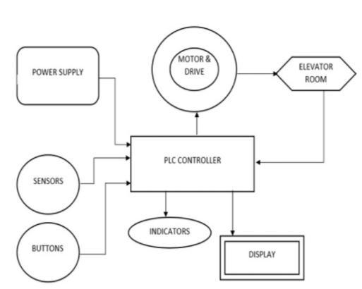
Fig. 1 BlockDiagramofPLCElevatorControl
TheuseofaPLCsystemcomeswithanumberofbenefits, includingitscompactsize,theabilitytobereprogrammed and customized, and the simplicity with which the application can be replicated and documented. PLC manufacturersonlyofferaclosed looparchitecture,which is one of the system's disadvantages, as well as the fact thatitrunsonapredeterminedcircuit.
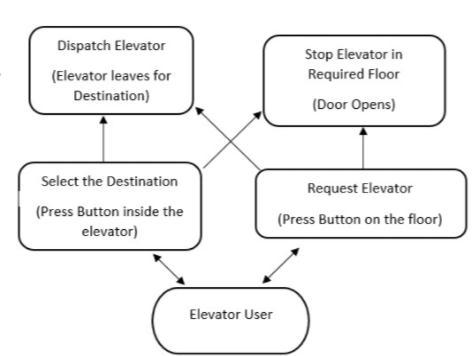
Fig. 2 UnderstandingtheFlow
International Research Journal of Engineering and Technology (IRJET) e ISSN:2395 0056
Volume: 09 Issue: 06 | Jun 2022 www.irjet.net p ISSN:2395 0072
PLC language uses some unique terms that are different fromtermsthatareuseddaily.Inordertounderstandthe working of the ladder logic there is a need to understand someofthetermsthatarementionedbelow:
1. Central Processing Unit (CPU) It is the PLC controller'sbrain.Itisoneofthemicrocontrollersand isresponsibleforcommunicationandinterconnection with other sections of the PLC controller, as well as program execution, memory operation, input monitoring,andoutputsetup.
2. Memory PLChastwotypesofmemoriesusednamely
a. Read Only Memory (ROM) The memory location which stores the symbols and other information necessary while the execution of theprogram.
b. Random Access Memory (RAM) The memory location that stores the calling functionsbasedontheladderlogics.
3. Power Supply The power necessary for the PLC to perform all the functions that are necessary was provided through an AC source. A 240V SMPS is used inthesimulation.
4. I/Omodule:TheI/OmoduleisaRackthatprovidesall the Necessary information to both the PLC and the user. It provides the address of all the inputs and outputs.
5. ProgrammingDevices:
a. Ladder Logic Diagram (LAD) It is a step diagramoftheLogicsthatisproposed forthe working of the elevator. It uses Symbols and components of the element in a line diagram thatshowsthehardwirecontrol.
b. StatementList(STL) Itisanotherviewofthe instructions provided to the PLC in the form oftext.Theoperationisshowntotheleftand theoperandisshowntotheright.
c. Function Block Diagram (FBD) It is a set of instructions in the form of a block diagram. Thefunctionsareindicatedbyarectangleand haveaspecifictask.
The interfacing Devices available for the PLC are given below:
a. Profibus
PointtoPointInterface USB
MultipointInterface USB
Ethernet The Interfacing Devices used are TCP/IP which is a collection protocol used for communication. It consists of 3 components: IP, TCPandUDP.
Fig. 3 SymbolTable
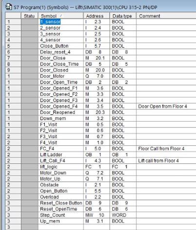
After careful investigation, some characteristics including motorratingsandautomobileweightwerecalculated.PLC CPUrequirementsweredependentonDCMotorandrope strength. Some knowledge on software compatibility and usability were required since it is simulation based. For a rudimentaryimplementation,theuseofswitchesandlogic like AND, NAND, OR, and XOR with NC and NO LAD switches. The inputs observed are 6 signals namely Car Location, Floor Buttons, Car Buttons, Car Movement (Direction),DoorStatus,andSignalTriggers.Thissignalis represented by the HMI Toolbox Button. With these factors in mind, the ladder logics were created and simulated.
The PLC continuously carries out 3 4 basic steps namely Error Check, Input scan, Logic scan, Output scan. Before running the program, the software checks for any
International Research Journal of Engineering and Technology (IRJET) e ISSN:2395 0056
Volume: 09 Issue: 06 | Jun 2022 www.irjet.net p ISSN:2395 0072
presence of any error. Input Scan is known as the inputs providedbytheuserarescannedbytheplcandstoredin the memory. Logic scan is the CPU of the PLC is the controller of the logic. It reads inputs, executes the programmestep by step,andupdatesoutput.Outputscan isthelogicscan'sfinalpresentationfrommemory.
Calculationshelpedchoosesimulationcomponentsforthe hardware implementation. In order to reduce the elevator's cost, the most versatile and reliable parts were needed.
CarSpecification: Weightofthecabin=100kg Counterweight= 100kg Limitof10peopleeachweighing65kg=650kg
Ropestrength:
F= mg ;F=(650+100+100)*9.8=8330N=8.33KNMotor Specification: Power: P= Force*Velocity;P=(650*9.8)N*1m/s=6370W Since,1hp=745W,6370W=8.55hp;9hp=6705W Torque:
T= P/2πω =6705/2π(1500)=31.5Nm
Ladder logic allows us to control door openings, travel direction, and time. Call buttons will move the car. Elevator motion affects the amount of power and time used.Motiveisfindinganefficientdesignandlogic.
STEP 7 can be used to programme SIMATIC S7 1500 and S7 300 Controllers and configure SIMATIC HMI Basic Panels. This functionality allows STEP 7 to do both. TIA Portal gives you unrestricted access to digitized automation services, from planning to engineering to operation. Siemens' SIMATIC WinCC is a simulation softwareforSCADAandHMIsystems.STEP7canbeused to programme SIMATIC S7 1500 and S7 300 Controllers andconfigureSIMATICHMIBasicPanels.
International Research Journal of Engineering and Technology (IRJET) e ISSN:2395 0056
Fig. 5 UpwardMovementLogic
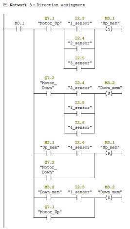
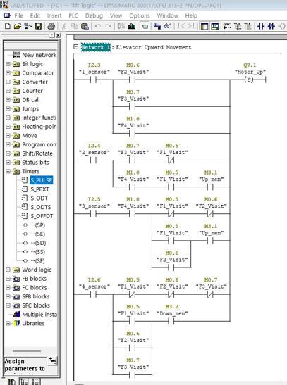
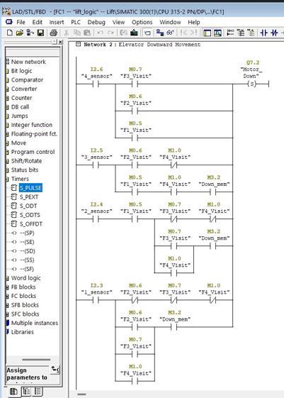
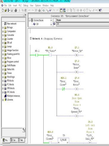
Fig. 6 DownwardMovementLogic
Fig. 7 DirectionAssignmentLogic
Fig. 8 StoppingElevatorLogic
Volume: 09 Issue: 06 | Jun 2022 www.irjet.net p ISSN:2395 0072 © 2022, IRJET | Impact Factor value: 7.529 | ISO 9001:2008 Certified Journal | Page 2885
International Research Journal of Engineering and Technology (IRJET) e ISSN:2395 0056
Volume: 09 Issue: 06 | Jun 2022 www.irjet.net p ISSN:2395 0072
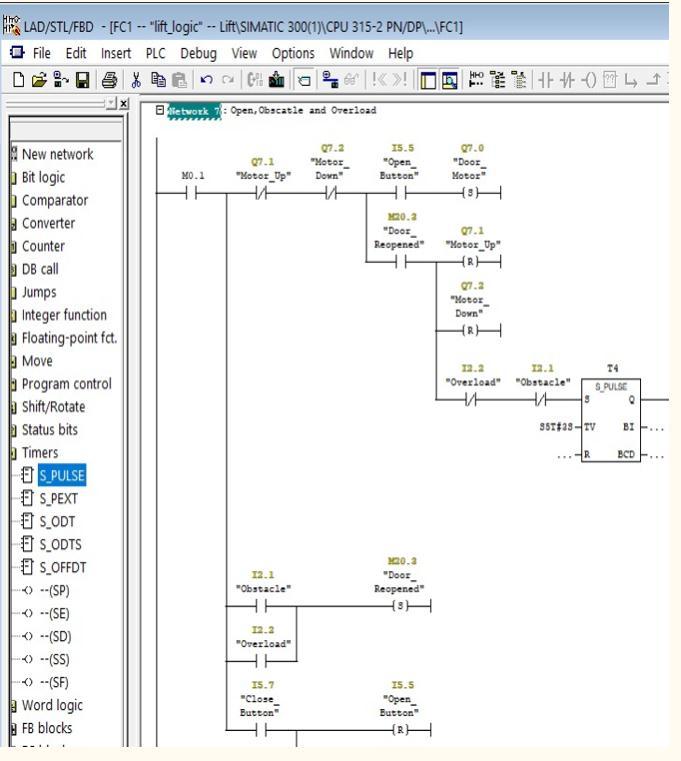
phone. When the signal from the level sensor on the secondfloorishigh,afloorcallisplaced.Everycallsignal on the second floor has been turned back to 0 now. After having been opened for a predetermined amount of time, the door is then closed in preparation for moving to the next level. When the door is shut, the car is able to move forward once more. If the door is closing, pressing the Openbuttonwillreopenit,andifitisalreadyopen,itwill reset the amount of time it has been open. When the passenger door is shut, the vehicle remains stationary untilitreceivesasignalfromtheOpenbutton.Intheevent that there is a barrier or that the elevator is too full, the door will either remain open or reopen. An HMI screen willdisplayalloftheoperationswhenyouaresimulating. The operation is the same in its entirety, with the exception of a PLC and switches (Buttons). When modelling,researchersneedtotakeintoaccountavariety offactorsthathavethepotentialtoaffectelevatormotion and put customers in harm's way. In order to determine whetherornottheelevatorismoving,fluctuatingelevator speed, and steady elevator slowing, the creation of the modeloughttocentreonenvironmentalanalysis.
Fig. 9 Open,ObstacleandOverloadLogic
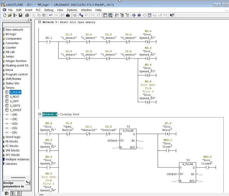
Thefirstfloormarksthebeginningoftheoperationforthe car. It makes no difference to the programme if the elevator is located on a different floor. The car is started by push buttons. It moves in an order that maximises the amount of power saved, so if the car is moving in one directionandanothercallcomesin,itwillrespondtoallof the calls in the first direction before it responds to any calls in the second direction. When the call signal and the floor sensor are a match, the elevator will hang up the
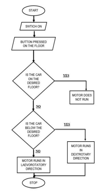
Following the completion of the error checking and the interfacing of the PLC with the elevator, the trials of the setup were carried out, and it was found that the setup functioned correctly. The operation begins with pressing the button for the desired flow, and if the elevator is already on that floor, the motor will start running according to it; for example, if the elevator is located below the desired floor, it will rotate in a clockwise direction,butifitislocatedabovethedesiredfloor,itwill rotate in a counter clockwise direction. There is a significant amount of room for advancement in this simulation, for instance. incorporating a weight sensor into the lift in order to establish a maximum permissible load for the lift to carry. Also, adding weight sensors to eachfloorsothatyoucankeeptrackofwhichfloorhasthe mostpeopleonit,oremployingaweightcounterbalancing technique, should be done in order to make it operationally feasible and for additional safety measures likesoundingthealarmwhentheweightoftheliftreaches the predetermined maximum level or when the door is unabletocloseduetosome obstacles,respectively. When thereareonlyafewstoriesinabuilding,thisisoneofthe most efficient and cost effective ways to implement an elevator. It is also possible to implement this using other Softwares, some of which have more features and are more compatible with one another that can drastically optimizethemodellinginrealtimescenarios.
International Research Journal of Engineering and Technology (IRJET) e ISSN:2395 0056
Volume: 09 Issue: 06 | Jun 2022 www.irjet.net p ISSN:2395 0072
Journal of Electrical and Computer Engineering. 8. 1947 1953.10.11591/ijece.v8i4.pp1947 1953.
[4] Han, Xiaohu. (2020). Design and research of elevator control systems based on PLC. Journal of Physics: Conference Series. 1449. 012101.10.1088/1742 6596/1449/1/012101.
[5] Soe, Theint. (2019). Design of PLC based Elevator Control System. International Journal for Research in Applied Science and Engineering Technology. 7. 416 421.10.22214/ijraset.2019.8058.
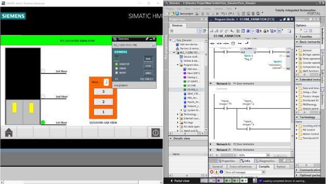
Fig. 11 LiveSimulationinTIAPortal
[6] Htay, Sandar and Yuyus Suryana. “Implementation of PLCBasedElevatorControlSystem.”(2014).

[7] Abdelkarim Ahmed Eltahir Ali, Zhang Jiang Min, "Design of Five Floors Elevator with SCADA System BasedonS7200PLC",InternationalJournalofScience and Research (IJSR), https://www.ijsr.net/get_abstract.php?paper_id=NOV 162845,Volume5Issue4,April2016,1309 1314.
[8] Thabet,HassaanTh.H.,IbraheemS.Jameel,andIsmail Abduljabar Hasan. “Rehabilitation of an Old TraditionalElevatorBasedonPLCTechniques”.Wasit JournalofEngineeringSciences6,no.3(December10, 2018):76–89.doi:10.31185/ejuow.vol6.iss3.106.
Fig. 12 WorkingInterfacewithHMI
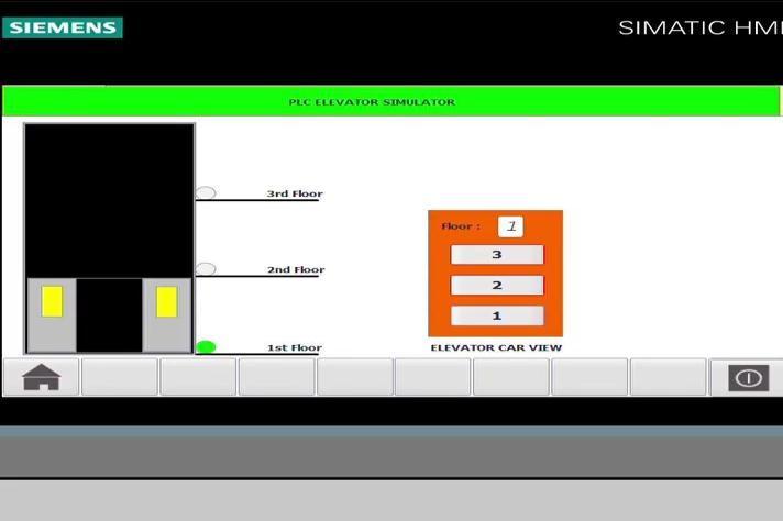
Simulation ran successfully. Logic inputs and outputs for elevatorforwardandreversemotoring,dooropeningand closing motor operation, and other sensors on each floor have been added, and the programme is evaluated and simulated using Graphic Interface. Simulations of logic have been created. The smaller size of wireless solutions makes changes easier and faster. Diagnostics which are centralizedandoverridesarebuiltintoPLCs.

[1] Gupta, Shrey. (2015). PLC based Multi Floor Elevator ControlSystem.IAESInternationalJournalofRobotics and Automation (IJRA). 4. 202. 10.11591/ijra.v4i3.pp202 208.
[2] Deepthi L R, Divya Dharshini J N, et.al (2021), Design and Implementation of Three Floor Lift Using PLC. International Conference on Advances in Materials, Computing and Communication Technologies (IJSRST),Vol9Issue1,April2021,ISSN2395 6011.
[3] Ali, Mohammed. (2018). Design and Implementation ofanElectricalLiftControlledusingPLC.International
[9] AditiDutta,Kajal,RasmitaGouda,“ElevatorOperation Control Through PLC”, Abhiyantriki International Journal ofEngineeringand Technology(AIJET), Vol.4 No.4,April2017.
[10] ThaiNguyen(2020).“PLCControllingProgramof anElevator”,HAMKUniversityofAppliedSciences.
AjithSrikanth
Student,B.TechMechatronics SRMInstituteofScienceand Technology
https://www.linkedin.com/in/as31/
NehaaV
StudentB.TechMechatronics SRMInstituteofScienceand Technology
https://www.linkedin.com/in/vn07/