International Research Journal of Engineering and Technology (IRJET) e ISSN: 2395 0056

Volume: 09 Issue: 06 | Jun 2022 www.irjet.net p ISSN: 2395 0072

International Research Journal of Engineering and Technology (IRJET) e ISSN: 2395 0056
Volume: 09 Issue: 06 | Jun 2022 www.irjet.net p ISSN: 2395 0072
Amrapali Shende1, Prof. Nandkishor Sinha2
2
1
***
Abstract Truss bridges appeared very early in the history of modern bridges and are economical to construct A bridge must be designed to safely resist all loads and forces that may reasonably occur during its life . These loads include not only the weight of the structure and passing vehicles, but also load from natural causes, such as wind load . The loads may act individually but more commonly occur as a combination of two or more loads applied simultaneously. In this paper to study the design of Pratt truss bridge and Warren truss bridge design and compare there results. The load effects like bending moment and shear force, Stress are to be found under factored load cases. The design is made based Finite element method. So in this study Pratt truss bridge and Warren truss bridge design and analysed by using ATUDESK STRUCTURAL ANALYSIS software and this software used to analysed and design the various types of structures like steel building , steel structures, truss bridges, etc. The study is made to compare the results of truss bridges of both Pratt truss bridge and warren truss type bridge, component, different parameter, load effect like stress, shear force, bending moment, deflection comparison, quantity of steel and concrete and construct and economical status . This both TRUSS bridges designed by AISC (American institute of steel construction) code and ASHTHO LRFD 2000 for loading. In this paper loading consider as dead load, wind load, as per AISC, moving load is H15 as per ASSTHO.
Key Words: Structuralanalysis,Warrentrussbridge,Pratt trussbridge, AUTODESKstructuralanalysisprofessionals software,AISC, ASHTHOLRFD2000,etc.
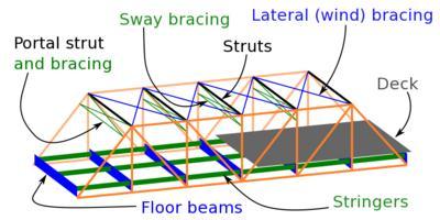
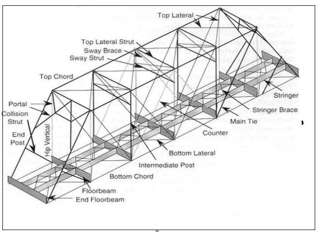
The truss bridges are a load bearing structures that theycontainmultipleverticalmember,horizontalmember, and diagonal members includes top chord, bottom chord Truss bridges are maximum strength with minimum material quantity . The main part of truss bridge is floor beams,stringers,portal strutandbracing,swaybracings, lateralwindbracings,anddeckthisallpartsoftrussbridge. The trusses support the bridge and its weight over large span areas.Every truss bridges contain top chord and a bottomchord,andthisbothchordishorizontalmember.The
Topchordsmemberis incompressionand bottomchords member in tension. Diagonals member or post are connected to the vertical and horizontal top chord and bottomchord member.Thesediagonalmembersmaybein compressionortension.Trussbridgesareone oldesttypes ofcommonandmodernbridges.Followingarethebridges comparedintheprojectthatbridgesarecommonbridgesis pratttrussbridgeandwarrentrussbridge.
Pratt truss bridges have been vertical members and diagonals membersthatmember slopewasdownwardto the centre. It is most commonly using for the railway bridges. The basic form of Pratt truss bridge includes triangular truss designs whose diagonal members slope towardthecenterofthebridge.Whenunderload,thisdesign makesdiagonalmembersaretension,and verticalmembers areinsuspension self).Ifthediagonal membersaremade from the solid material such as metal bars, and when for heavyload bridgemayneedsneedforimplementationfor reinforcementstothecenterareaofthePratttrussbridge, sincethatpartofthebridgewillalwaysthestrongestforce loadsinbridge. Pratttrussbridgesarestaticallydeterminate structure. ThePratttrussbecamewidelyadopted,because itsdesignwastheverysimple design, economicalalso,and
International Research Journal of Engineering and Technology (IRJET) e ISSN: 2395 0056
easilyerectionofthisbridge inthefield.Followingfigures showtheallpartsoftrussbridge.
bridgeisdesignbyAISC(AMERICANINSTITUTEOFSTEEL CONSTRUCTION) Standard,andmovingloadonbridgeis as perASSTHOLRFDSpecificationmovingloadonbridge H15 loading Theanalysisanddesigningphaseoftheseproject work was done by using AUTODESK STRUCTURAL ANALYSIS PROFESSIONAL software. And calculate the quantity of steel and concrete compare which bridge is economicalbridgeonweightofmaterial
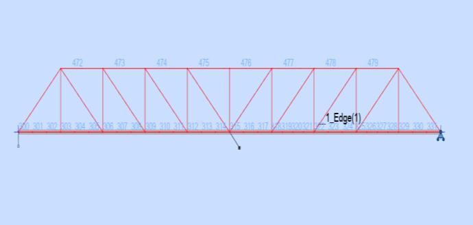
“Analyze and Design of Pratt truss bridge and Warren truss bridge as per AISC Code , ASSTHO LRFD 2000 specification,movingloadappliedonbridgeisH15loading, top length of bridge is 25.60m, bottom length of bridge is 32.00m,heightofbridgeis3m,no.offieldsare10,RC flooris10inchthick.
(1) Toanalyse anddesignofPratttrussbridgeasperAISC method and ASSHTHO LRFD 2000 specification by using Autodeskstructuralanalysisprofessional2022software.
Fig.2 componentofPratttrussbridge
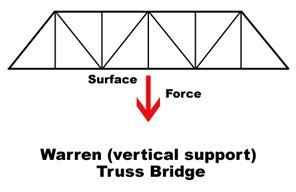
Warren truss bridge also contain top chord bottom chord,anddiagonalbracingsandstringersinthebridgeand deckalso.Warrentrussbridgehasbeencontainlongitudinal members vertical and horizontal and diagonal member in thebridge.Andinthisbridge memberjoinedonlyby the anglecross members.Thistypeoftrussbridgeformbyethe equilateral triangles in the truss . this bridge is relatively light but this bridge was strongest and economical truss bridge Theequilateraltrianglesminimizetheforcestoonly compressionandtension.
(2) Toanalyse anddesignofWarren trussbridgeasper AISC method and ASSHTHO LRFD 2000 specification by using Autodesk structural analysis professional 2022 software.
(3)Tocomparethe resultmaximumandminimummoment, reaction,stress,displacementondifferentloadcondition.
(4) ToCalculatequantityofmaterialandcomparetheboth quantity.
(5)Tomatchquantityofsteelmaterialsbyusingweightand compare the different of quantity of material , find out economicaltrussbridge.
2.
1.Projecttopicfinalization.
Literaturesurvey.
Planningoftrussbridge.
AnalysisanddesignofPratttrussusingAISCStandard.
InThisresearchpaper tostudythetypesoftruss bridgei.e.Pratttrussbridge andWarrentrussbridge,and the parameter like stress, bending moment, shear force, displacement,ofbothbridgeandcomparethe results.The
Analysis and design of Warren truss bridge using AISC standard. 6.Calculationofquantityofsteel&reinforcement. 7.Comparingtherespectiveresultsofbothpratttrussbridge andwarrentrussbridge. 8.Conclusion.
The truss bridge is analyzing as per AISC , Material properties of steel member is as per American standard,
Volume: 09 Issue: 06 | Jun 2022 www.irjet.net p ISSN: 2395 0072 © 2022, IRJET | Impact Factor value: 7.529 | ISO 9001:2008 Certified Journal | Page2878
International Research Journal of Engineering and Technology (IRJET) e ISSN: 2395 0056
sectiondatabaseasperAISC15.0Americanhotrolledshape (AISC Edition 15.0), and loading on the truss bridge dead load, wind load , data base is ASCE minimum design load ASCE7 .05and movingloadisasperASSTHOspecification, steeldesignasperLRFD2000 andthesupportisprovidedat 1sideis pinnedsupportandothersideisrollersupporton trussbridge.
i)Analysisofdeadload,windload isdonebyusingtheAISC with the help of AUTODESK STRUCTURAL ANALYSIS PROFESSIONALS2022software.
ii)Analysisofmoving loadi.e.vehicleloadisASPERAASTHO specification is carried out with the help of Autodesk structuralanalysissoftwaresteeldesignasperLRFD2000.
Design data : Lengthoftopchord=32m
Lengthofbottomchord=25.6m
Height=3m No.offields=10nos
Loading on bridge is wind load, dead load, live load, movingloadCodeAASHTO
Vehiclename H15 Loadtype
Concentratedload: F=53.38KN, X=0m,S=1828.8mm
Concentratedload: F=53.38KN, X=4267.2mm, S=1828.8mm
SECTION PARAMETERS: : TOPCHORD HP18X181
BOTTOMCHORD:: W16X67
DIAGONALS: L3.5x3.5x0.25,L6X6X3/4, L5X5X3/4,L 3.5x3.5x0.25, L3x3x0.1875,
Fig 4. (FrontView)2 DLinePlanof Pratt Trussbridge.
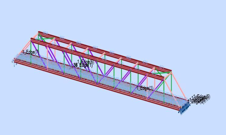
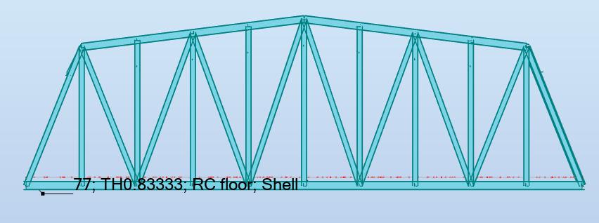
Fig 5. (3DView)3Dviewof PrattTrussbridgemodel.
CODE: LRFD Specification for Structural Steel Buildings, December 29,1999
ANALYSIS TYPE: MemberVerification CODE GROUP: Member: 209 Simplemember Point: 3 Coordinate: x=0.53L=17.07m LOADS: Governing Load Case: 9MOVINGLOAD/18/ 9/18*1.00 MATERIAL: STEELFy=248.21MPa
SECTION
W16X67
MEMBER PARAMETERS: Ly=32.00m KLy/ry=180.58 Lb=32.00m Lz=32.00m KLz/rz=511.29 Cb=1.00
INTERNAL FORCES: NOMINAL STRENGTHS: Mux= 0.00kN*m fuvy,mx=0.00MPa Pu= 38.13kN fuvz,mx=0.00MPa Pn=3138.67kN
Volume: 09 Issue: 06 | Jun 2022 www.irjet.net p ISSN: 2395 0072 © 2022, IRJET | Impact Factor value: 7.529 | ISO 9001:2008 Certified Journal | Page2879
International Research Journal of Engineering and Technology (IRJET) e ISSN: 2395 0056
Volume: 09 Issue: 06 | Jun 2022 www.irjet.net p ISSN: 2395 0072
Muy=33.76kN*m Vuy= 0.08Kn Mny=87.53kN*m Vny=1173.10kN Muz=0.02kN*m Vuz=20.63kN Mnz=144.39kN*m Vnz=618.62kN
COEFFICIENTS: Fib=0.90 Fit=0.90 Fiv=0.90
SECTION ELEMENTS: UNS=Compact STI=Compact
VERIFICATION FORMULAS:
Pu/(2*Fit*Pn)+(Muy/(Fib*Mny)+Muz/(Fib*Mnz))= 0.44<1.00 LRFD(H1 1B) Vuy/(Fiv*Vny)+fuvy,mx/(0.6*Fiv*Fy)=0.00<1.00 Vuz/(Fiv*Vnz)+fuvz,mx/(0.6*Fiv*Fy)=0.04<1.00 LRFD (F2 2)(H2 2)
Section OK !!!
CODE: LRFD Specification for Structural Steel Buildings, December 29,1999
ANALYSIS TYPE: MemberVerification
CODE GROUP:
MEMBER: 2 POINT: 2 CODE: LRFD Specification for Structural Steel Buildings, December 29,1999
ANALYSIS TYPE: MemberVerification
CODE GROUP: MEMBER: 2 POINT: 2 COORDINATE: x =0.44L=11.20m
LOADS: Governing Load Case: 1DL1 MATERIAL: STEEL Fy=248.21MPa
SECTION PARAMETERS: HP18X181 d=457mm Ay=23226mm2 Az=11613mm2 Ax=34323mm2 b=457mm Iy=1257018905mm4 Iz=405409409mm4 J=8615991mm4 tw=25mm Sy=5498770mm3 Sz=1773444mm3 tf=25mm Zy=6210697mm3 Zz=2736640mm3
MEMBER PARAMETERS: Ly=25.60m KLy/ry=133.77Lb=25.60m Lz=25.60m KLz/rz=235.55 Cb=1.00
INTERNAL FORCES: NOMINAL STRENGTHS: Mux=0.01kN*m fuvy,mx=0.02MPa Pu=473.86kN fuvz,mx=0.02MPa Pn=1070.61kN
Muy=52.79kN*m Vuy=0.17kN Mny=937.20kN*m Muz= 0.48kN*m Vuz= 0.12kN Mnz=679.26kN*m COEFFICIENTS: Fib=0.90 Fic=0.85 Fiv= 0.90
SECTION ELEMENTS: UNS=Compact STI=Compact VERIFICATION FORMULAS: Pu/(Fic*Pn)+8/9*(Muy/(Fib*Mny)+Muz/(Fib*Mnz))= 0.58<1.00 LRFD(H1 1A) Vuy/(Fiv*Vny)+fuvy,mx/(0.6*Fiv*Fy)=0.00<1.00 Vuz/(Fiv*Vnz)+fuvz,mx/(0.6*Fiv*Fy)=0.00<1.00 LRFD (F2 2)(H2 2) Section OK !!!
MEMBER: 5 POINT: COORDINATE: LOADS: Governing Load Case: Manual MATERIAL: STEEL Fy=248.21MPa
SECTION PARAMETERS: L6X6X3/4 d=152mm Ay=2903mm2 Az=2903mm2 Ax=5458mm2 b=152mm Iy=11696103mm4 Iz=11696103mm4 J=670133mm4 tw=19mm Sy=108714mm3 Sz=108860mm3 tf=19mm Zy=195006mm3 Zz=195006mm3
MEMBER PARAMETERS: Ly=4.39m KLy/ry=94.75 Lz=4.39m KLz/rz=94.75
INTERNAL FORCES: Mux= 0.00kN*m fuvy,mx=0.11MPa Pu=492.04kN fuvz,mx=0.11MPa Pn=844.47kN Vuy=0.35kN
NOMINAL STRENGTHS: Vny=432.37Kn Muz=0.96kN*m Vuz=0.67kN Mnz=48.40kN*m Vnz=432.37kN
COEFFICIENTS: Fib=0.90 Fic=0.85 Fiv=0.90
SECTION ELEMENTS: UNS=Non compact STI=Compact
VERIFICATION FORMULAS:
Pu/(Fic*Pn)+8/9*Muz/(Fib*Mnz)=0.71<1.00 LRFD (H1 1A) Vuy/(Fiv*Vny)+fuvy,mx/(0.6*Fiv*Fy)=0.00<1.00 Vuz/(Fiv*Vnz)+fuvz,mx/(0.6*Fiv*Fy)=0.00<1.00 LRFD (F2 2)(H2 2)
Section OK !!!
© 2022, IRJET | Impact Factor value: 7.529 | ISO 9001:2008 Certified Journal | Page2880
International Research Journal of Engineering and Technology (IRJET) e ISSN: 2395 0056
d=89mm
MEMBER: 11 POINT: 2 COORDINATE: x=0.50L=2.19m LOADS: Governing Load Case: 1DL1 MATERIAL: STEEL Fy=248.21MPa
Ay=565mm2 Az=565mm2 Ax=1097mm2 b=89mm Iy=832463mm4 Iz=832463mm4 J=16067mm4 tw=6mm Sy=12845mm3 Sz=12873mm3 tf=6mm Zy=23106mm3 Zz=23106mm3
MEMBER PARAMETERS:
Ly=4.39m KLy/ry=159.21 Lz=4.39m KLz/rz=159.21
SECTION PARAMETERS: L5X5X3/4 d=127mm Ay=2419mm2 Az=2419mm2 Ax=4503mm2 b=127mm Iy=6534833mm4 Iz=6534833mm4 J=553588mm4 tw=19mm Sy=73794mm3 Sz=73930mm3 tf=19mm Zy=133391mm3 Zz=133391mm3
MEMBER PARAMETERS: Ly=4.39m KLy/ry=115.15 Lz=4.39m KLz/rz=115.15
INTERNAL FORCES:
Mux= 0.00kN*m fuvy,mx=0.11MPa Pu= 399.99kN fuvz,mx=0.11MPa Pn=1117.75kN
NOMINAL STRENGTHS:
INTERNAL FORCES:
Mux=0.00kN*m fuvy,mx=0.01MPa Pu= 159.68kN fuvz,mx=0.01MPa Pn=272.23kN
NOMINAL STRENGTHS:
Muy=0.15kN*m Vuy= 0.00kN Mny=5.74kN*m Vny=84.07kN Muz= 0.00kN*m Vuz=0.00kN Mnz=5.74kN*m
COEFFICIENTS: Fib=0.90 Fit=0.90 Fiv=0.90
SECTION ELEMENTS:
UNS=Slender STI=Compact VERIFICATION FORMULAS: Pu/(Fit*Pn)+8/9*(Muy/(Fib*Mny)+Muz/(Fib*Mnz))= 0.68<1.00 LRFD(H1 1A) Vuy/(Fiv*Vny)+fuvy,mx/(0.6*Fiv*Fy)=0.00<1.00 Vuz/(Fiv*Vnz)+fuvz,mx/(0.6*Fiv*Fy)=0.00<1.00 LRFD (F2 2)(H2 2)
Muy=0.61kN*m Vuy= 0.06kN Mny=33.11kN*m Vny=360.31kN Muz=0.04kN*m Vuz=0.00kN Mnz=33.11kN*m Vnz=360.31kN
COEFFICIENTS: Fib=0.90 Fit=0.90 Fiv=0.90
SECTION ELEMENTS: UNS=Non compact STI=Compact
VERIFICATION FORMULAS: Pu/(Fit*Pn)+8/9*(Muy/(Fib*Mny)+Muz/(Fib*Mnz))= 0.42<1.00 LRFD(H1 1A) Vuy/(Fiv*Vny)+fuvy,mx/(0.6*Fiv*Fy)=0.00<1.00 Vuz/(Fiv*Vnz)+fuvz,mx/(0.6*Fiv*Fy)=0.00<1.00 LRFD (F2 2)(H2 2)
Section OK !!!
CODE GROUP: MEMBER: 8 POINT: 2 COORDINATE: x=0.50L=2.19m
LOADS: Governing Load Case: 1DL1 MATERIAL: STEEL Fy=248.21MPa
SECTION PARAMETERS: L 3.5x3.5x0.25
Section OK !!!
MEMBER PARAMETERS: Ly=3.00m KLy/ry=126.65
Volume: 09 Issue: 06 | Jun 2022 www.irjet.net p ISSN: 2395 0072 © 2022, IRJET | Impact Factor value: 7.529 | ISO 9001:2008 Certified Journal | Page2881
International Research Journal of Engineering and Technology (IRJET) e ISSN: 2395 0056
Lz=3.00m KLz/rz=126.65
INTERNAL FORCES: Mux= 0.00kN*m fuvy,mx=0.00MPa Pu= 28.51kN fuvz,mx=0.00MPa Pn=174.55kN
NOMINAL STRENGTHS: Vuy= 0.00kN Vny=54.05kN Muz= 0.01kN*m Vuz=0.00kN Mnz=3.15kN*m
COEFFICIENTS: Fib=0.90 Fit=0.90 Fiv=0.90
SECTION ELEMENTS: UNS=Slender STI=Compact
VERIFICATION FORMULAS:
Pu/(2*Fit*Pn)+Muz/(Fib*Mnz)=0.09<1.00 LRFD (H1 1B) Vuy/(Fiv*Vny)+fuvy,mx/(0.6*Fiv*Fy)=0.00<1.00 Vuz/(Fiv*Vnz)+fuvz,mx/(0.6*Fiv*Fy)=0.00<1.00 LRFD (F2 2)(H2 2)
Section OK !!!
Design data : Lengthoftopchord=32m
Lengthofbottomchord=25m Height= 7m No.offields=10nos
Loading on bridge is wind load, dead load, live load, movingloadCodeAASHTO Vehiclename H15 Loadtype
Concentratedload: F=53.38KN, X=0m,S=1828.8mm
Concentratedload: F=53.38KN, X=4267.2mm, S=1828.8mm
Fig 7. (FrontView)3 Dviewof Warren Trussbridge. Design of steel member section STEEL MEMBER DESIGN

CODE: LRFD Specification for Structural Steel Buildings, December 29,1999 ANALYSIS TYPE: MemberVerification
SECTION PARAMETERS: : TOPCHORD W18X97 BOTTOMCHORD:16X89 DIAGONALS: L8X8X3/4,L6X6X3/4, L5X5X3/4, L3.5x3.5x0.25,L3x3x0.1875, W12X45,W12X65,W18X97,W12X50,W12X53,
CODE GROUP: MEMBER: 1 POINT: COORDINATE: x=0.80L=80.00ft LOADS: Governing Load Case: 2WIND1 MATERIAL: STEEL Fy=248MPa
SECTION PARAMETERS: W18X97 d=470mm Ay=1250mm2 Az=640mm2 Ax=184mm2 b=28cm Iy=728400mm4 Iz=83660 mm4 J=244mm4 tw=1cm Sy=30840mm3 Sz=5930mm3 tf=2cm Zy=34580mm3 Zz=9060mm3
MEMBER PARAMETERS: Ly=32m KLy/ry=153.14 Lb=32m Lz=32m KLz/rz=451.86 Cb=1.00
INTERNAL FORCES: Mux=0.00KN*m fuvy,mx=0.00MPa Pu=26.334kn.m fuvz,mx=0.00MPa Pn=155.87KN
Volume: 09 Issue: 06 | Jun 2022 www.irjet.net p ISSN: 2395 0072 © 2022, IRJET | Impact Factor value: 7.529 | ISO 9001:2008 Certified Journal | Page2882
Fig 6. (FrontView)2 DLinePlanof Warren Trussbridge.International Research Journal of Engineering and Technology (IRJET) e ISSN: 2395 0056
NOMINAL STRENGTHS:
Muy= 0.00kN.m Vuy= 0.00KN Mny=613.23kn.m
Vny=375.46kip Muz= 4.67kn.m Vuz=0.04KN Mnz=737.96KN.m Vnz=214.94kip
COEFFICIENTS: Fib=0.90 Fic=0.85 Fiv= 0.90
SECTION ELEMENTS:
UNS=Compact STI=Compact VERIFICATION FORMULAS: Pu/(2*Fic*Pn)+(Muy/(Fib*Mny)+Muz/(Fib*Mnz))= 0.02<1.00 LRFD(H1 1B) Vuy/(Fiv*Vny)+fuvy,mx/(0.6*Fiv*Fy)=0.00<1.00 Vuz/(Fiv*Vons)+fuvz,mx/(0.6*Fiv*Fy)=0.00<1.00 LRFD(F2 2)(H2 2) Section ok
Table -1: MaximumAndMinimumReactionForce Calculation Reaction Force(Kn) DeadLoad (Value) WindLoad (Value) Moving Load H15 (Value) MAX (KN) MIN (KN) MAX (KN) MIN (KN) MAX (KN) MIN (KN)
Fz=10kN 13.20 13.12 4.49 4.34 5.88 40.3 9 Fy=10kN 26.41 27.30 7.13 53.42 8.32 1.31 FX=5KN 23.28 28.82 9.02 8.93 8.00 9.04
Table -2: MaximumAndMinimumMoment Calculation
Normal Stress (Mn/M2)
Stressmax= 50 (MN/M2)
DeadLoad (Value) WindLoad (Value) Moving Load H15 (Value)
Max (MN/M2 )
min (MN/M 2)
Max (MN/M 2)
min (MN/M 2)
Max (MN/ M2)
min (MN/ M2)
S(Max) 38.00 13.53 61.67 1.62 8.83 4.83
S(Min) 20.89 42.12 1.63 61.91 13.97 240.4 0
Bending Stress (Mn/M2)
Bend Stress max=50 (MN/M2)
DeadLoad (Value) WindLoad (Value) Moving Load H15 (Value)
Max (MN/M 2)
min (MN/M 2)
Max (MN/ M2)
min (MN /M2)
Max (MN/ M2)
min (MN/M 2)
S Max (My) 8.73 1.71 2.83 0.08 166.5 2 8.74
SMax (Mz) 121.04 1.91 60.55 0.17 36.06 10.24
S Min(My) 3.66 211.18 0.16 2.11 17.20 166.79
1.33 17.2
MOMENT (KN/M) DeadLoad (Value) WindLoad (Value) Moving Load H15 (Value) MAX (KN/M )
MIN (KN/ M)
MAX (KN/M )
MIN (KN/M) MAX (KN/ M)
MIN (KN/ M)
Mz=50kN m 38.00 13.53 19.01 7.13 8.83 4.83 My=10kN m 20.89 42.12 4.21 5.78 13.97 240. 40 Mz=5kn m 0.38 1.44 0.50 0.04 0.16 0.58
142 95958 1520100504.62 Concrete
Volume: 09 Issue: 06 | Jun 2022 www.irjet.net p ISSN: 2395 0072 © 2022, IRJET | Impact Factor value: 7.529 | ISO 9001:2008 Certified Journal | Page2883
Table 1: MaximumAndMinimumReactionForce Calculation
Reaction Force (Kn)
DeadLoad (Value)
WindLoad (Value) Moving Load H15 (Value)
Bending Stress (Mn/M2)
DeadLoad (Value) WindLoad (Value) Moving Load H15 (Value)
Max (MN/M 2)
MAX (KN) MIN (KN) MAX (KN) MIN (KN) MAX (KN) MIN (KN) Fz=5kN 100.86 99.54 0.41 0.81 26.4 6 27.1 7 Fy=5kN 2.64 2.98 0.22 0.16 0.40 0.48 FX+C, FX T =100KN
Bend Stress max=50 (MN/M2)
min (MN/ M2)
Max (MN/ M2)
min (MN/ M2)
Max (MN/M2 )
min (MN/M2 )
S Max (My) 22.84 1.83 3.40 0.04 14.95 0.22
SMax (Mz) 11.43 1.91 4.38 0.10 4.39 0.30
S Min (My) 2.25 11.12 0.02 3.88 0.35 14.95
985.65 506.79 2.98 3.04 146. 01 76.3 1
Table 5: MaximumAndMinimumMomentCalculation moment (KN/M) DeadLoad (Value) WindLoad (Value) Moving Load H15 (Value) MAX (KN/M) MIN (KN/M )
SMin (Mz) 2.03 24.33 0.10 3.82 0.35 3.57
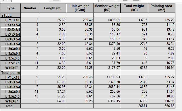
Bill Of Quantity & Material Pratt Truss Bridge
MAX (KN/M )
MIN (KN/M )
MAX (KN/ M)
3.59 0.97 0.16 0.14 0.69 0.23
MIN (KN/ M) MZ=10k N/m 4.53 3.96 0.84 0.39 1.10 0.92 My=10k N 237.11 136.45 0.51 0.59 65.5 9 36.8 8 MX=e 003 KN/m
Table -6: MaximumAndMinimumnormalStress CalculationResult
Normal Stress (Mn/M2)
{A}Forwarrentrussbridge :SteelTakeoff=95958kg
Max (MN/M 2)
min (MN/M 2)
Max (MN/M 2)
min (MN/M 2)
DeadLoad (Value) WindLoad (Value) Moving Load H15 (Value) Stress max= 50 (MN/M2)
min (MN/ M2) S(Max) 97.92 142.60 0.56 3.94 19.31 40.63 S(min) 88.81 150 01 4.27 0.54 19.01 42.63
Max (MN/ M2)
TotalQuantityinkg=95958kg ofsteels/crequired {B}Forpratttrussbridge: SteelTakeoff=26877kg 1}TotalQuantityinKg =26877kgsteel s/crequired
International Research Journal of Engineering and Technology (IRJET) e ISSN: 2395 0056 Volume: 09 Issue: 06 | Jun 2022 www.irjet.net p ISSN: 2395 0072 © 2022, IRJET | Impact Factor value: 7.529 | ISO 9001:2008 Certified Journal | Page2884
International Research Journal of Engineering and Technology (IRJET) e ISSN: 2395 0056
Volume: 09 Issue: 06 | Jun 2022 www.irjet.net p ISSN: 2395 0072
Therefore,Costofwarrentrussbridge=95958x67 =Rs.6429186/ CostofPratttrussbridge=26871x67 =Rs.1800357/
Therefore, Total Cost Saving Pratt truss bridge =6429186 1800357 Rs.4628829/
Therefore 56.24% of the total cost saving in Pratt truss bridgesothatPratttrussbridge isprovedtobeeconomical bridgeascomparedtowarrentrussbridge.
[1] V.R. Shinde, Prof. A.S. Patil , (2021)“Comparative analysisandoftrussbridges,”IJERT,vol.10,Jan 2021 ISSN:2278 0181,publishbyhttp://2278 0181
[2] GopalDayaramPal1,AshrafPatel2,NirajMeshram3, Sayyed Aamir Hussain (2021) “A Review Study On DifferentTrussTypeRailwaySteelBridge”JISRED,vol.4, 3May June2021,www.ijsred.com.
[3] 1. Safwan Asghar abbas “Designing a Truss Bridge” (2020) https://www.researchgate.net/publication/348579526 DOI:10.13140/RG.2.2.12015.05282
[4] Ankit Sharma1 Sumit Pahwa2 “A Review Study on BridgeTrussStructureAnalysis”IJSRD&Development| Vol.6,Issue02,2018|ISSN(online):2321 0613.
[5] Josh. J. Oliveira 1, Antonia. J. Reis(2015) “composite truss bridges, design & reaserch” https://www.researchgate.net/publication/348579526 DOI:10.13140/RG.2.2.12015.05282
[6] JorgeTito Izquierdo1(2010)“StructuralEvaluationOf A Truss Pedestrian Bridge” University Of Houston, DowntownAlbertoGomez Rivas,UniversityOfHouston, Downtown © American Society For Engineering Education,2010
[7] AmericanAssociationofStateHighwayTransportation Officials,AASHTOLRFDBridgeDesignSpecifications4th edition.
[8] American Institute of Steel Construction. ANSI/AISC 360 05, Specifications for Structural Steel Buildings, March2005
[9] American Society of Civil Engineers Structural Engineering Institute. Minimum Design Loads for BuildingsandOtherStructures,ASCE/SEI7 05.
[10] Computers & Structures, Inc., “AUTODESK ROBOT STRUCTUR ANALYSIS PROFESSION Software for Structural Analysis & Design, Technical Reference Manual”
1’st Author Photo
2nd Author Photo
Amrapali Shende 1,(M Tech2nd Year Student), Structural and Construction Engineering Department, Ballarpur Institute ofTechnology.
Prof. Nandkishor sinha2 , (AssistantProfessor),Structural and Construction Engineering Department, Ballarpur institute ofTechnology.
© 2022, IRJET | Impact Factor value: 7.529 | ISO 9001:2008 Certified Journal | Page2885