International Research Journal of Engineering and Technology (IRJET) e ISSN: 2395 0056

Volume: 09 Issue: 06 | Jun 2022 www.irjet.net p ISSN: 2395 0072
International Research Journal of Engineering and Technology (IRJET) e ISSN: 2395 0056
Volume: 09 Issue: 06 | Jun 2022 www.irjet.net p ISSN: 2395 0072
1M.Tech Student, Dept. of Civil Engineering, Indiragandhi Institute of Polytechnic and Engineering, Kerala, India
2 Assistant Professor, Dept. of Civil Engineering, Indiragandhi Institute of Polytechnic and Engineering, Kerala, India
3 Head of Department, Dept. of Civil Engineering, Indiragandhi Institute of Polytechnic and Engineering, Kerala, India ***
Abstract – This study of numerical analysis discuss about spiral bolt connection in beam column joint with and without flange opening and flange removal connection for seismic application And also discuss about the temperature influence in beam and column with and without open condition. Then it will find out a suitable dimension of web and flange opened spiral beam column connection. Then next step is the study of web and flange opening condition in unstiffened I beam . Here, modeling and analysis is done by finite element software ANSYS .This model used elastic plastic analysis to follow the behavior upon formation of up to four plastic hinges involved in the entire yielding mechanism.. Strain hardening and truss action are included in this method. . The comparison of the analytical results gave the method which provides a curve , which is usable to make nonlinear element models for beam column connections composed
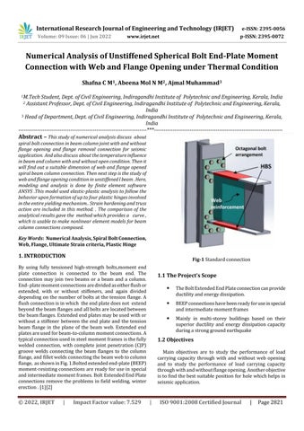
By using fully tensioned high strength bolts,moment end plate connection is connected to the beam end. The connection may join two beams or a beam and a column. End platemomentconnectionsaredividedaseitherflushor extended, with or without stiffeners, and again divided depending onthe number ofboltsatthetension flange. A flushconnectionisinwhich theendplatedoesnot extend beyondthebeamflangesandallboltsarelocatedbetween thebeamflanges.Extendedendplatesmaybeusedwithor without a stiffener between the end plate and the tension beam flange in the plane of the beam web. Extended end platesareusedforbeam to columnmomentconnections.A typicalconnectionusedinsteelmomentframesisthefully welded connection, with complete joint penetration (CJP) groove welds connecting the beam flanges to the column flange,andfilletweldsconnectingthebeamwebtocolumn flange, asshowninFig.1.Boltedextendedend plate(BEEP) moment resistingconnectionsareready foruseinspecial andintermediatemomentframes.BoltExtendedEndPlate connectionsremove theproblemsin field welding, winter erection.[1][2]
TheBoltExtendedEndPlateconnectioncanprovide ductilityandenergydissipation.
BEEPconnectionshavebeenreadyforuseinspecial andintermediatemomentframes
Mainly in multi storey buildings based on their superior ductility and energy dissipation capacity duringastronggroundearthquake
Main objectives are to study the performance of load carrying capacity through with and without web opening and to study the performance of load carrying capacity throughwithandwithoutflangeopening.Anotherobjective istofindthebestsuitablepositionforholewhichhelpsin seismicapplication.
International Research Journal of Engineering and Technology (IRJET) e ISSN: 2395 0056
Thefollowingisthemethodologyusedfortheproject:
Literature survey: Adetailedreviewoftheliteratureonthis topicisdonethroughmanyjournals.Itgave somefindings regarding the project topic A literature review was undertakenusingjournals,textbooks,andconferencepapers etc.
Fixing the objectives: The next step is to fixing the objectives that means to identify what weare going to do. Afterthemodelingandanalysis,wegettheanswerforour objectives.
Numerical validation: It is done by using finite element software ANSYS based on the journal am selected for validation.
Development of analytical model of structure in ANSYS workbench : ThemodelforanalysisisdevelopedinANSYS workbench. It is a finite element analysis tool used for structural analysis for linear, non linear and dynamic studies.
Analysis of model : Firstanalysisisbasedonchangingthe diameter of the hole and after that the position of hole is changed. Then,delayingstrengthdegradationtechniqueis used.
Comparison of result and Interpretation : After the analysis,allthemodelsgetcomparedandreachedinafinal conclusion.
ANSYS workbench is a software which is used for doing analysisofstructural,thermal,andelectromagnetic.ANSYS structural analysis software helps to solve structural engineeringproblemsandmakeresultfaster.Validationis doneonthebasisofthejournal AnUnstiffenedEight Bolt Extended End Plate Moment Connection for Special and Intermediate Moment Frames, Journal of Structural Engineering, Volume 145 Issue 7 published by Machel L. Morrison,DougQ.Schweizer,ShahriarQuayyumandTasnim Hassan(2021).[1]
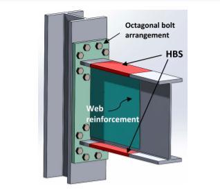
Thedetailsofgeometryandconnectionsareshowninfig2.1.
i. Beam:W760X220ASTMA992
ii. Column:W360x382ASTMA992
iii. Bolt:38.1mmdiaASTMA490
iv. Endplate:1124x387x44.5mmASTMA572Gr50
v. Webreinforcementplate:762x660x35mmASTM A572Gr50
vi. HBS
Fig 3.1.Connectiondetails
Thepropertiesofdifferentstructuralelementslikebeam, column,bolt,HBS,endplateisshownintable4.1.
Table 1: MaterialPropertiesofElements
Properties Value
Density 7850kg/m3
Coefficientofthermalexpansion 1.2e 05c 1 Young’smodulus 2e+11Pa Poissonsratio 0.3 Tensileyieldstrength 2.5e+08Pa Isotropicthermalconductivity 60.5Wm 1c 1 Specificheatconstantpressure 434Jkg 1c 1
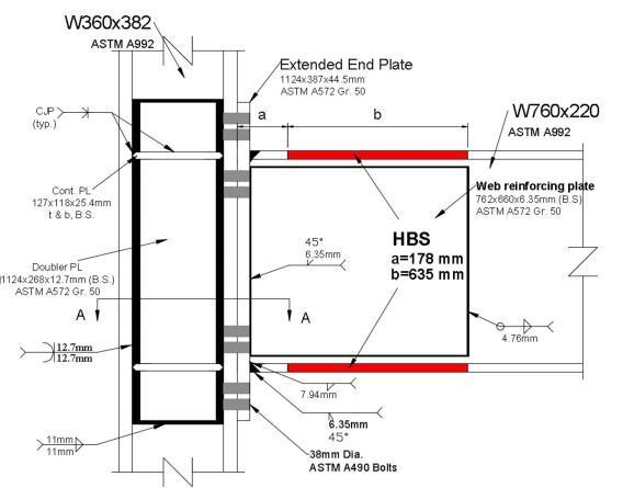
Fig 3.2.Stressstrainrelationship
Volume: 09 Issue: 06 | Jun 2022 www.irjet.net p ISSN: 2395 0072 © 2022, IRJET | Impact Factor value: 7.529 | ISO 9001:2008 Certified Journal | Page2822
International Research Journal of Engineering and Technology (IRJET) e ISSN: 2395 0056
Volume: 09 Issue: 06 | Jun 2022 www.irjet.net p ISSN: 2395 0072
Thestressstrainrelationshipisobtainedfromthefig2.2and thevaluesarenotedinatabularcolumnasshownintabe2.
Table 2 Valuesofplasticstrainandstress
Plastic strain Stress (MPa)
0 5 0.000311 158.45 0.00059 223.39 0.0008 241.68 0.00844 288.6 0.021 343.44 0.0444 385.38 0.07369 403.91 0.10074 418.61 0.1318 420 0.1693 422
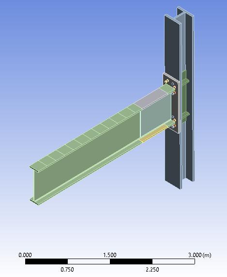
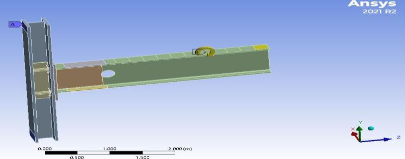
GeometryofthemodelledisdevelopedusingANSYS Workbench21.Themodelofproposedbeamcolumnjoint isshowninfig2.3
Fig 3.4
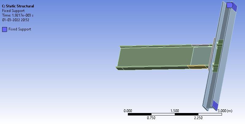
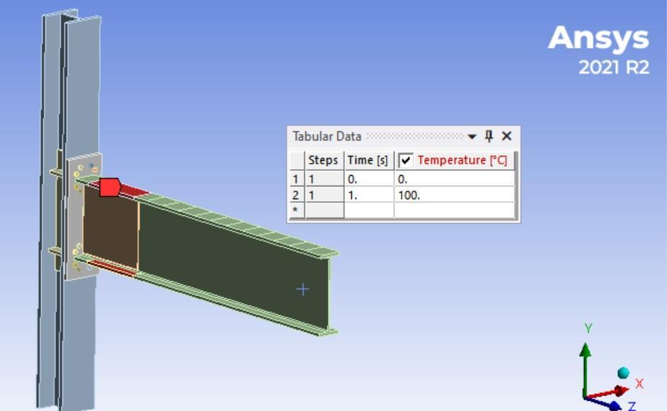
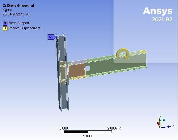
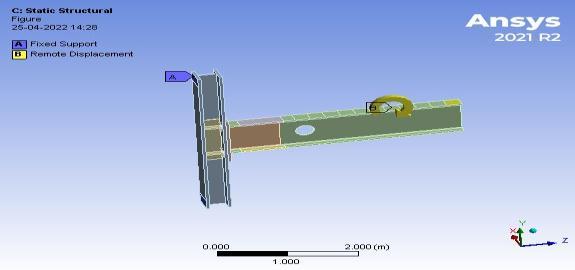
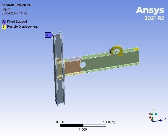
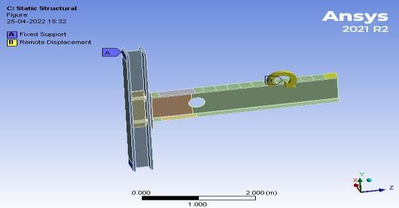
Oncemeshingisdone,boundaryconditionisassignedtothe structure here it is fixed along the column and a remote displacementontipofthebeamalongxdirectionasshown infig 2.5and 2.6.Cyclicloadingisgivenatthelastfaceof splitofbeam.
Fig 3.3. Modelofproposedbeamcolumnjoint
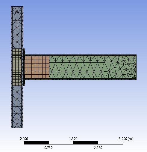
Meshing is an important step in the analysis using ANSYS Software. The Beam, column, end plate, and beam to end plateCJPweldweremodelledusing8 nodedsolidelements andtheBoltsweremodelledusing20 nodedsolidelements. Solid 186 is the element type used for meshing. The structureaftermeshingisshownin2.4
Fig 3.5. Supportcondition
International Research Journal of Engineering and Technology (IRJET) e ISSN: 2395 0056
Volume: 09 Issue: 06 | Jun 2022 www.irjet.net p ISSN: 2395 0072
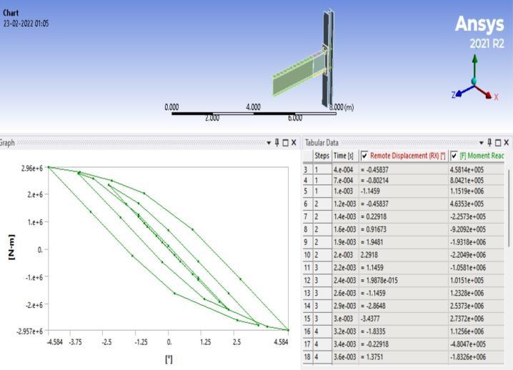
HysteresisCurveisprovidedbelow.
Fig 3.6.Remotedisplacement
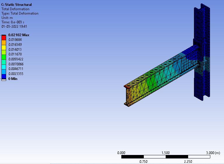
Afterthevalidationitisobtainedthatthetotaldeformation obtainedisabout0.02102mm.
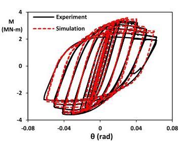
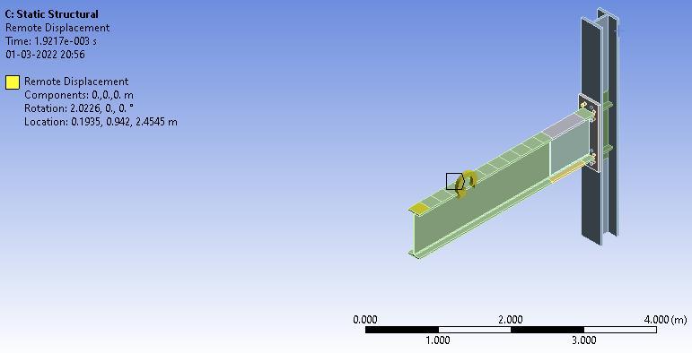
Fig 3.9. Remotedisplacement
Theexperimentalmaximummomentfromthejournalgraph is3.2MN m.Maximummomentfromthevalidationgraphis 2.96 MN m. So the percentage difference between the maximum moments from the two graph is 0.925 %. Hysteresis curve is obtained assimilar to the curve in the groupwhichisshowninfig3.10
Fig 3.7.Remotedisplacement
Thetemperaturethatprovidedfortheanalysisisabout 1000
Fig 3.10 MomentResponsegraph
ThemostpopularfiniteelementanalysissoftwareisANSYS workbenchR21.TheelementtypeusedisSOLID186forthe model
Fig 3.8. Remotedisplacement
International Research Journal of Engineering and Technology (IRJET) e ISSN: 2395 0056
Volume: 09 Issue: 06 | Jun 2022 www.irjet.net p ISSN: 2395 0072
Infourthcasethediameteroftheholeisincreasedby296.81 mm.
Fig 4.1.Model1
Infirstcasethediameteroftheholeisincreasedby223mm. The propertyofthisconnectionisthearrangementofbolts inanoctagonalpatternasshowninFig.4.1TBysystematic FEanalysisofstiffenedandunstiffenedeight boltextended end plate connections with various bolt arrangements, octagonal pattern is developed. Tensile forces from the beamflangeandwebwillcausebiaxialbendingoftheend plateinthisconnection..Theoctagonalboltpatterncarries thisbiaxialbendingandincreasesuniformforcedistribution intheboltgroup.
Insecondcasethediameteroftheholeisincreasedby245.3 mm.
Fig 4.2 Model2
Inthirdcasethediameteroftheholeisincreasedby269.83mm.
Fig 4.4 Model4
Infifthcasetheparametricstudywasbasedonchangingthe positionofholesby935mm.
Fig 4.5.Model5

Insixthcasetheparametricstudywasbasedonchangingthe positionofholesby1028.5mm.
Fig 4.6 Model6
Inseventhcasetheparametricstudywasbasedonchanging thepositionofholesby1131.35mm.
Fig 4.3 Model3
Fig 4.7 Model7
International Research Journal of Engineering and Technology (IRJET) e ISSN: 2395 0056
Ineighthcasetheparametricstudywasbasedonchanging thepositionofholesby1244.48mm.
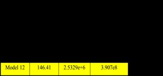
Inthiscasetheflangeremovalisatadiameterof146.41mm.
Fig 4.8 Model8
Inninthcasetheflangeremovalisatadiameterof110mm.
Fig 4.9 Model9
Intenthcasetheflangeremovalisatadiameterof121mm.
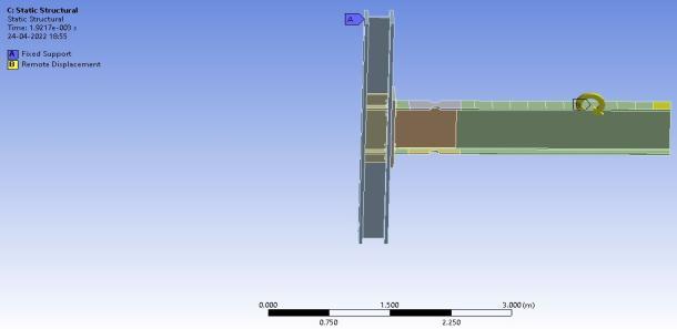
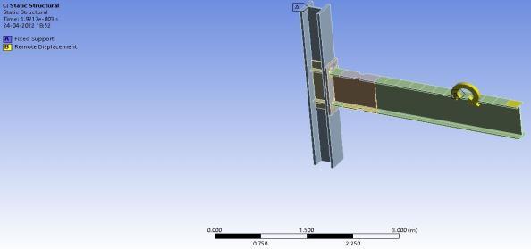
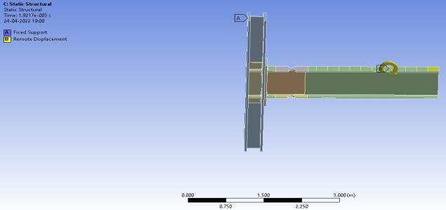
Fig 4.12 Model12
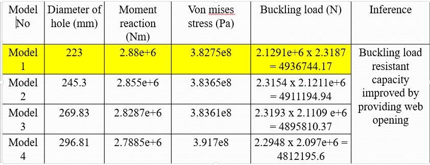
Afterthechangesaremadeinthemodel,analysisweredone. Analysisaremainlydonetodeterminethemomentreaction, Vonmisesstress(Pa),Bucklingload(N)ofvariousmodel.
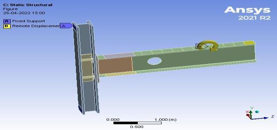
Table 3 Increasingdiameterofholebyvariousdiameter
Fig.4.10 Model10
Inthiscasetheflangeremovalisatadiameterof133.1mm.
Fromthetableaboveitisclearthatthemodel1havinghigh buckling load as compared to others. So buckling load resistantcapacitycanbeimprovedbythewebopening.
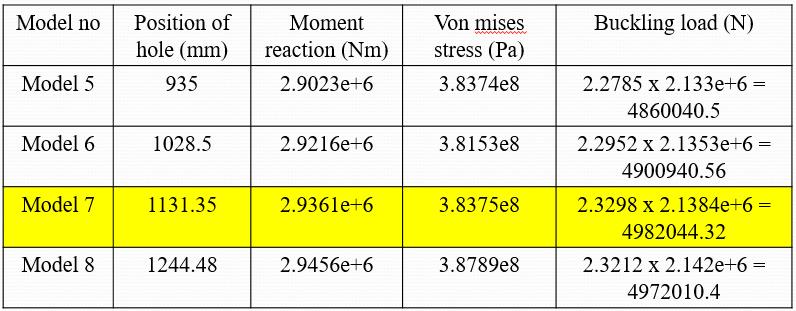
Table 4 Changingthepositionofholebyvariousdiameter
Fromthetableitisclearthatthemodel7havehighbuckling loadascomparedtoothers.
Fig 4.11 Model11
Volume: 09 Issue: 06 | Jun 2022 www.irjet.net p ISSN: 2395 0072 © 2022, IRJET | Impact Factor value: 7.529 | ISO 9001:2008 Certified Journal | Page2826
International Research Journal of Engineering and Technology (IRJET) e ISSN: 2395 0056
Special and Intermediate Moment Frames”, Journal of StructuralEngineering,Volume145Issue7
[2] Xiaohui Zhang, Shansuo Zheng, Xuran Zhao (2019), Seismicperformanceofsteelbeam to columnmoment connectionswithdifferentstructuralforms,“Journalof ConstructionalSteelResearch,Volume158,Pages130 142,ISSN0143 974X
[3] Yasin Onuralp Özkılıç, Cem Topkaya (2021), “The plasticandtheultimateresistanceoffour boltextended end plateconnections”,JournalofConstructionalSteel Research,Volume181,106614,ISSN0143 974X
Fromthetableaboveitisclearthatthemodel16withflange removal is from a hole diameter of 146.41mm shows less momentreactionascomparedtoothers.Sointhiscaseless stressaswellaslessfailurewilloccur.
This study report discuss about an unstiffened different types of bolt arrangement for seismic applications. The connection provides a bolt arrangement which help to increaseuniformdistributionofforcesthroughoutthebolt group.Itdescribestheresultsof testingoftheunstiffened different types of bolts by using ANSYS Workbench. The details of experimental developments are done using the ANSYSsoftware.Itisclearthatmodel1andmodel7having highbucklingloadascomparedtoothers.Sobucklingload resistant capacity can be improved by using the web opening. Model 16 with flange removal is from a hole diameter of 146.41mm shows less moment reaction as comparedtoothers.Sointhiscaselessstressaswellasless failurewilloccur.
Itakethisopportunitytoexpressmysinceregratitudeand sincerethankstoallwhohelpedmetocompletethework successfully.Myfirstandforemostthanksto God Almighty whoshoweredhisimmenseblessingsonmyeffort.Iwould liketoexpressmy gratitudeto Dr. Senthil Kumar,Principal ofIIPEforgivingmesuchopportunitytodomyproject.I would like to express my gratitude to Dr. Ajmal Muhammad,HeadofDepartment,CivilEngineering,IIPE, forhisencouragementincompletingtheProject.Iamdeeply indebtedtomyguide Mrs. Abeena Mol N M,Asst.Professor, Department of Civil Engineering, I I P E, for her valuable guidance,encouragement,suggestionsinthecompletionof theproject
[1] Machel L. Morrison, Doug Q. Schweizer, Shahriar QuayyumandTasnimHassan(2021), “AnUnstiffened Eight BoltExtendedEnd PlateMomentConnectionfor
[4] Vlada Gašić, Aleksandra Arsić, Nenad Zrnić (2021), “Strengthofextendedstiffenedend plateboltedjoints: Experimental and numerical analysis,” Structures, Volume33,Pages77 89,ISSN2352 0124
[5] XiaoyiLan,ShuaiLi,OuZhao(2021),“Localbucklingof hot rolledstainlesssteelchannelsectionstubcolumns after exposure to fire”, Journal ofConstructional Steel Research,Volume187,106950,ISSN0143 974X
[6] Asan Mahjoob Behrooz, Saeed Erfani (2020), “ParametricstudyofStub BeamBoltedExtendedEnd Plate connection to box columns,” Journal of Constructional Steel Research, Volume 171, 106155, ISSN0143 974X
[7] Xue Chun Liu, Yue Wang, Xiao Xiong Cui, Cheng Yu, Zheng XianBai(2020),”Seismicperformanceofbolted beam to columnconnectionwithrib stiffenedsplicing plate,”JournalofConstructionalSteelResearch,Volume 174,106300,ISSN0143 974X
[8] Chen, Jingsi Huo, Wensu Chen, Hong Hao, Ahmed Y. Elghazouli,(2020), “Experimental and numerical assessmentofweldedsteelbeam columnconnections underimpactloading,”Journal ofConstructional Steel Research,Volume175,106368,ISSN0143 974X
[9] AshrafElSabbagh,TarekSharaf,SalahNagy,Mohammed ElGhandour, (2019), “Behavior of extended end plate bolted connections subjected to monotonic and cyclic loads,”EngineeringStructures,Volume190,Pages142 159,ISSN0141 0296
[10] JothiarunDhanapal,HosseinGhaednia,SreekantaDas, Jonathan Velocci, (2020),” Behavior of thin walled beam column modular connection subject to bending load”, Thin Walled Structures, Volume 149, 106536, ISSN0263 8231
[11] Hamdolah Behnam, J.S. Kuang, Bijan Samali (2018), “Parametric finite element analysis of RC wide beam columnconnections”,Computers&Structures,Volume 205,Pages28 44,ISSN0045 799
Volume: 09 Issue: 06 | Jun 2022 www.irjet.net p ISSN: 2395 0072 © 2022, IRJET | Impact Factor value: 7.529 | ISO 9001:2008 Certified Journal | Page2827
International Research Journal of Engineering and Technology (IRJET) e ISSN: 2395 0056
[12] X.C. Liu, X.N. He, H.X. Wang, A.L. Zhang (2018), “Compression bend shearing performance of column to column bolted flange connections in prefabricated multi high risesteelstructures,”EngineeringStructures, Volume160,Pages439 460,ISSN0141 0296
[13] Machel Morrison, Shahriar Quayyum, Tasnim Hassan (2017), “Performance enhancement of eight bolt extended end plate moment connections under simulated seismic loading”, Engineering Structures, Volume151,Pages444 458,ISSN0141 0296
Volume: 09 Issue: 06 | Jun 2022 www.irjet.net p ISSN: 2395 0072 © 2022, IRJET | Impact Factor value: 7.529 | ISO 9001:2008 Certified Journal | Page2828