International Research Journal of Engineering and Technology (IRJET) e ISSN: 2395 0056

Volume: 09 Issue: 06 | June 2022 www.irjet.net p ISSN: 2395 0072
International Research Journal of Engineering and Technology (IRJET) e ISSN: 2395 0056
Volume: 09 Issue: 06 | June 2022 www.irjet.net p ISSN: 2395 0072
Department of Mechanical Engineering, Vishwakarma Institute of Technology, Pune 48, Maharashtra, India ***
Abstract - Considering the emissions caused by road transport, electric vehicles are being considered as the future or personal and commercial transport. We are already witnessing the adaptation of electric vehicles considering the cost of fossil fuels rising as the days pass. Many major countries are considering banning the sales of combustion vehicles as early as 2025; hence, the adaptation of EVs is inevitable.
Key Words: EV, bike, sustainable transportation, renewableenergy.
The drawback of the internal combustion engine (ICE) is pollution. Hence, the requirement to find out an appropriate substitute has notably increased in recent years.Hybridelectricvehicles(HEVs)andElectricvehicles (EVs)arethesubstituteiftheICEsincetheyarecapableof operating with lower impact on the environment. However, EV’s have did not gain popularity because of a single problem, the energy storage capacity of electrical batteriesismuchlessthanthatoffossil fuels,soitcannot beusedfora longerdrive. However,inrecentyearsthere hasbeendevelopmentinthetechnologyofthe EVs,which solvestheaboveproblem.
Inthispaper,wehavedesignedanelectricbike,whichwill have high efficiency and will overcome the problem of performance decline on low battery power. Analysis has also been performed on various components of the bike suchaschassis,shockabsorber.
1. Chassis: It is the backbone of electric motorbike and is made up of M.S. along with some additional lightweightcomponents.Thechassisisdesignedtosustain the weight of the person driving the unit, the weight of load to be conveyed and to hold the accessories like battery.
2. Swing arm: A swing arm or swinging arm, originally known as a swing fork or pivoted fork, is the main component of the rear suspension of most modern motorbikesandATVs.Itisusedtoholdtherearaxlefirmly whilepivotingvertically,toallowthesuspensiontoabsorb bumpsintheroad.
3. Steering:Itisusedtoturnthebikeasperourchoice.
4. Suspension system: The suspension serves a dual purpose of contributing to the vehicle's handling and braking, and providing safety and comfort by keeping the vehicle'spassengerscomfortablyisolatedfromroadnoise, bumpsandvibrations.Thefront suspension isofthetype telescopicfork.
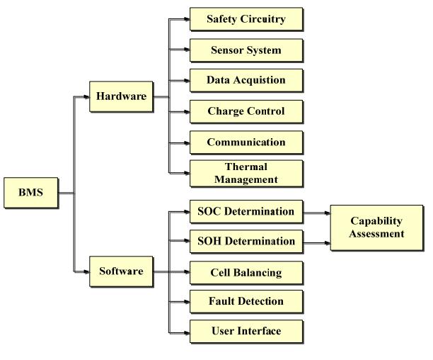
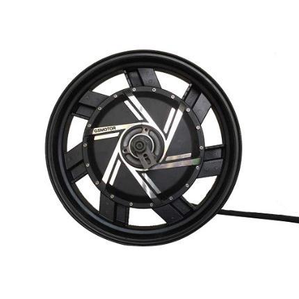
5. Brushless DC (BLDC) Motor: A brushless DC electric motor, also known as an electronically commutatedmotor(ECMorECmotor)orsynchronousDC motor,isasynchronousmotorusingadirectcurrent(DC) electric power supply The wheel hub motor (also called wheel motor, wheel hub drive, hub motor or in wheel motor) is an electric motor that is incorporated into the hub of a wheel and drives it directly. The specification of motorusedare4000W72VDChubmotorandtheweight ofthemotoris26kg.
6. Wheels:
7. Motor controller: A motor controller is a device that controls possibly every action of the motor A 72 volt 150 amperes motor controller is used it is designed such as it controls every operation, which includes speed control of the motor and Braking system. A Motor controlleristhebrainofthemotor.Amotorcontrollerisa combination of power electronics and embedded micro computingelements,whichmaketheconversionofenergy stored in batteries of an electric vehicle to generate motion.
8. Brakes: Brakes are used to stop a vehicle from moving. In an electric motorcycle, brakes play an important role as the electric motorcycle moves at high speed so in case of any unknown scenario brakes should beofagoodtypetostoptheelectricmotorcycleandavoid accidents.
9. Battery: The battery is the powerhouse of an electric motorcycle so to make a Motorcycle design that has a very good range a rechargeable battery should be usedasitcanberechargedandused.
International Research Journal of Engineering and Technology (IRJET) e ISSN: 2395 0056
Volume: 09 Issue: 06 | June 2022 www.irjet.net p ISSN: 2395 0072
When a person buys an EV, the top concern is the safety and reliability of the power system in a vehicle. The most importantquestioniswhethertheywillrunoutofbattery power on the road. These issues refer to the estimation and prediction of SOC, SOH, and SOL of the EV battery. Thus, an accurate quantification of the battery status has become one of the most critical tasks for BMSs. In this section, the latest methodologies for battery state estimationandpredictionarereviewed.
SOCiscritical,butitcannotbemeasuredwiththecurrent onboard sensing technologies. The ratio of the currently available capacity to the maximum capacity can be expressedasSOC,whichiscalculatedbyEquation(1): SOC = …(1)
Where i is the current and Cn is the maximum capacity thatthebatterycanhold.
SOH reflects the health condition of the battery and its abilitytodeliverspecific performancecomparedtoa new battery. A new feature was called sample Entropy (SampEn) was proposed which served as an indicator of SOH.
SampEn(m,r,N)= whereNisthetotalnumberofdatapoints,misthelength of sequences to be compared, r is the tolerance parameters, isthemeanvalueoftwosimilarsignal segments that are composed from input vectors with m points, and is similar to and will match form1points.
3. Stateoflife(SOL) SOL is also known as remaining useful life (RUL) of a battery
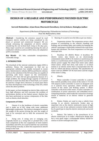
Aproposedbatterymanagementsystem:
Battery management system has two parts Hardware and Software. Their further classification is shown in picture below:
1. Hardware:
Safety circuitry is used in BMS for a long time but due to the advance development of BMS there has been addition of alarms and controls to prevent overcharge, over discharge,andoverheatingofthebattery.
The sensor system has different sensors to monitor and measurebatteryparametersincludingcellvoltage,battery temperatureandbatterycurrent.
Data acquisition (DAQ) and data storage are important parts in the BMS to analyze and build a database for systemmodeling.
The charge control system is an important sub system of the BMS, which is responsible for the charge discharge protocol.
Communication in BMS mostly happens through a Controlled Area Network (CAN bus). With the development of smart batteries, with help of micro controller the communication between the battery chargingtimeandusercanbedeveloped.
Thermal management is critical because temperature differences have an impact on cell imbalance, reliability andperformance.
2. Software:
The determination of SOC and SOH is integrated into a capability assessment, which represents the life status of the battery and sets the operating limits according to the algorithmsused.
International Research Journal of Engineering and Technology (IRJET) e ISSN: 2395 0056
Volume: 09 Issue: 06 | June 2022 www.irjet.net p ISSN: 2395 0072
The main objective of cell balancing is to maximize the battery performance without overcharging of over dischargingofthebattery.
Fault detection is required to provide battery fault warningandtoindicateout of toleranceconditions.
The user interface is used to display the essential information such as the remaining range, abnormal alarming and replacement suggestions of the battery to theusers.
The challenges that the vehicle BMSs are facing are given below
1. Capacity Estimation under Varying Loads and EnvironmentalTemperatures
2. Estimationofmaximumcapacity The capacity of the battery is calculated by Capacity =
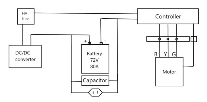
A. Electricalconnections
HV(Highvoltage)
1. Motor
2. Controller
3. Battery
LV(Lowvoltage)
1. Light
2. Speedometer
B. Motor QS 273 17inch E Scooter Hub Motor(40H) 4000WV3Type
Longer the integration time, the higher the battery capacitywillbe.
The communication in the BMS happened thought CAN bus; the battery transmits data such as current condition, usagehistorySOCindicationthrough SMBus.It isdifficult to make such mechanisms and different applications. Wireless technology helps to gather the external environmentdata,likehumidity,temperature,andableto communicatebetweenthebatteryandthecharger.
Assessment of battery health is very important. The batterytechnologyinEVisnotyetwelldevelopedsothere is a specific need for building a large database. The increaseincell resistance,decreaseinactual capacityand numberofchargeanddischargecyclesarethefactorsthat canbeusedtoevaluatethehealthstatusofthebattery.
As the number of EVs used are increasing the disposal of the batteries have become a significant issue. The best solutiontothisisrecyclingthebatteries.Teslareusestheir 60%ofthebattery’smaterials,whichisagratestrategy.
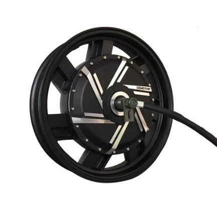
Figure 2 Hub motor (1)
Figure 3 Hub motor (2)
17.RearForkwidthforinstallation:200mm
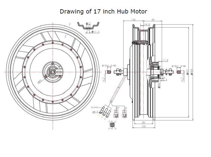
18.CrossSectionofPhasewire:16mm2/3phase 19.Hallsensorphasingangle:120degree 20.TemperatureSensor:KTY84 130 21.WorkingTemperature:70degrees,Peak120degree 22.WaterproofGrade:IP66
23.W./G.W.:24kgs/25kgs 24.PackageSize:58*58*40cm
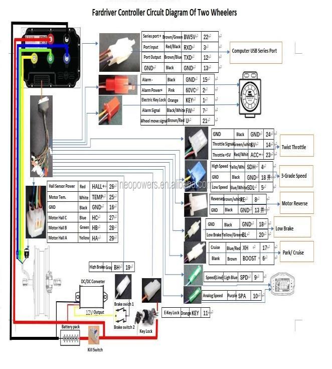
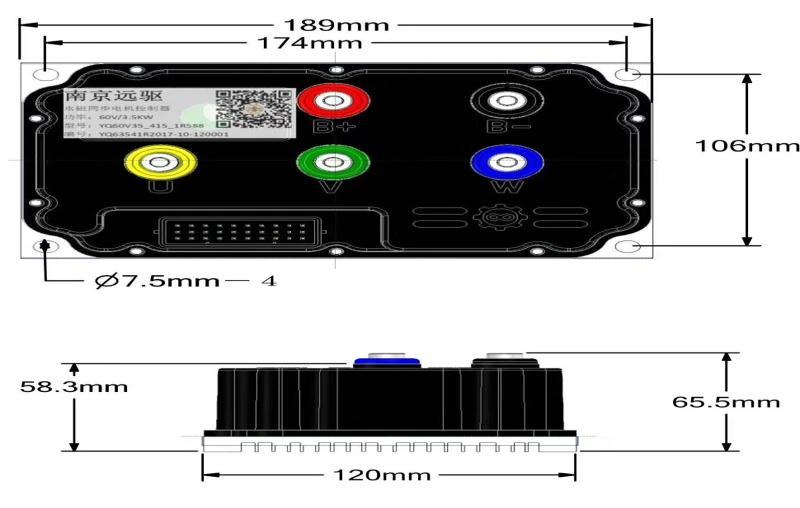
C. For driver Sine Wave Brushless Motor Controller ND72490
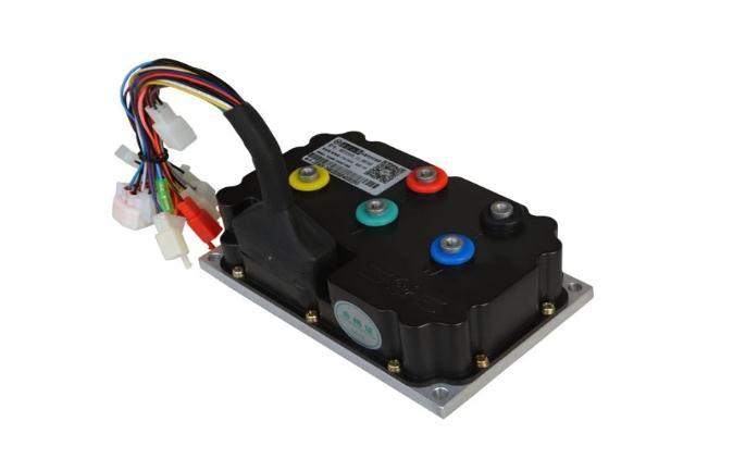
ModelNumber:ND72490
Max.BusCurrent:180A
Max.PhaseCurrent:660A
WorkingVoltage:52V 90V Size:189mm*121mm*63.5mm
Weight:2Kgs
Support Regen and Programmable by USB cable or Bluetooth Circuitdiagram:
Figure 6 Main circuit diagram Figure 7 Motor Controller (1)
International Research Journal of Engineering and Technology (IRJET) e ISSN: 2395 0056
Volume: 09 Issue: 06 | June 2022 www.irjet.net p ISSN: 2395 0072
Copperwire
6mmto8mmcopperwire(HV)
2mmto6mmcopperwire(LV)
H. Charger 15A,72V(ACtoDC)
Thechargerisconnectedparalleltothebattery
I. Accessories Blinkers
Taillight
Headlight
ODO,multi,speedometer
J. Handling/Braking/Shock up
Rackangle 24°
Braking Discbrake(Front+Rear)
Shockup Telescopic(Front),Monoshock(Rear)
K. Disc Brake Assembly Kits
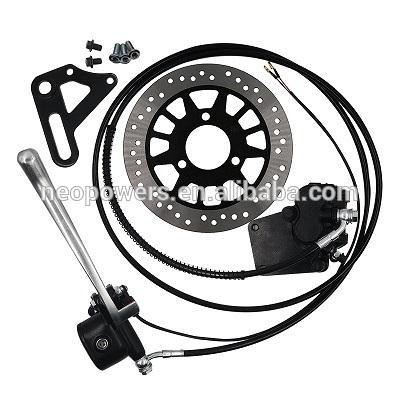
RearHubMotorDiscBrakeKits
Brakediscdiameter:220mm
Brakediscthickness:3.5mm
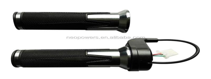
L. Twist Throttle
HallTwistThrottle
Innerholediameter2.3mm
Throttlebarlength=15cm
International Research Journal of Engineering and Technology (IRJET) e ISSN: 2395 0056
Wiresdefinition:
ThinRedwire+5V
BlackwireGND WhitewireHallSignal
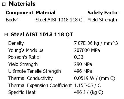
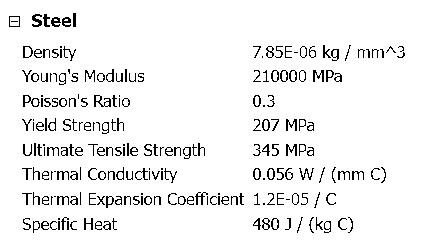
M. Chassis 2*1(inch) Rectangular casing Seamless (Mild Steel)
N. Body 2mmsheetmetal
O. Front (ktm rc 200 wheel suspension, brake caliper, mastercylinder,tripleclamp,bearing.bearinghousing)
P. Tempsensor KTY84 130
Worktemp=70°Cto120°C(100°C cutoff)
IP66Rated,weight=25kg
Super capacitor connected parallel to battery pack and controller. Main use of capacity pack is to maintain instantaneousvoltageandascapacitorareeasyandfastto chargecomparedtobatterypack.Regenerativeenergycan be used to charge capacitors rather than battery, which givesusmoreeffectiveregenerativeuses.
Busbar
1. Faradcapacitor 2.7V,500F
36*60mmsupercapacitor
2. 3.5mm,2.7V,500F
Balanceboard,supercapacitor,stabilization protection
A. Motor RPM/Torque
3. Weight Battery=40kg
Controller=2kg
Motor=25kg Material=15kg
Otherweight=15kg Kerbweight=97kg 20kgpayload,75kgavg.personweight
Total weight = 192 kg (200 kg)
4. Tiresize(rear)=17inch
For80km/hr
Tirerimdiam.=17inch*25.4=432mm
Rubbertireheight=130*0.7=91mm
Totaltirediam.=432+(91+91) =614mm
Total tire radius = 307 mm
5. Tirecircumference=2*Π*r =2*3.14*307 =1927.96mm(1928mm)
Linear travel of tire in 1 revolution = 1928 mm (2 m for calculations)
For80km/hr 80km/hr=22.22m/s
RPMrequiredforthisspeed=speed/lineartravel =22.22/2=11.11RPS =(22.22*60)/2=666.6RPM
Therefore, for 80 km/hr speed, the minimum RPM required from the motor must be ≥ 667 RPM
Bike frontage resistance (Standard data)
Bikefrontageresistance=Bikewidth*totalheight
Bikewidth=715mm
Bikeheight=Rider+Bike =1115+600 = 1715 mm
Volume: 09 Issue: 06 | June 2022 www.irjet.net p ISSN: 2395 0072 © 2021, IRJET | Impact Factor value: 7.529 | ISO 9001:2008 Certified Journal | Page2450
International Research Journal of Engineering and Technology (IRJET) e ISSN: 2395 0056
Volume: 09 Issue: 06 | June 2022 www.irjet.net p ISSN: 2395 0072
Bikefrontageresistance=715*1715 =1.22*106mm2 = 1.2 m2
the bike
1. Total resistance = Rolling resistance + Grad. Resistance+Drag+Inertia
a. Rollingforce(Fr)=f(mg)… (Due totireon road)
f = Coefficient of friction (tarmac/ standardroad) m=totalmass g=accelerationduetogravity=9.8m/s2 Fr =0.02*(200*9.8) = 39.2 kg.m/s2 = 39.2 N
b. Dragforce/Aerodynamicforce(Fd) Dragforce=(½)*ρ*c*v2*A ρ=densityoftheair c=coeff.ofdrag v=velocity A=Frontalarea Fd=(½)*1.2*0.8*(22.2)2 = 289.87 N
c. Accelerationforce/inertiaforce(Fa) Fa =ma a=Δv/t =((40 0)*100)*(15*3600)=0.74m/s2 Fa=200*0.74m/s2 = 148 N (100 N for calculation)
d. Gradientforce(Fg) Actswhendrivingonaninclinedsurface Fg =mgcosθ forθ=5°
=200*9.8*0.23 (Hypothetical)
Totalforces=Fr+Fd+Fa+Fg =39.2+282.87+148+176.58 = 646.65 N
Power(P)=+F(Total)*V = 646.65 * 22.22 = 14355.63 W
C. Motor selection (Torque)
P=2��NT/60
N=RPM T=Torque 14355=2*��*666.6*T/60 T = 205N m (Required torque)
(Practical)
Totalforces=Fr+Fg+Fa =39.2+282.87+100=422.07N
Power(P)=F*V=422.07*22.2=9378.3W 9378.3=P=2��NT/60 =2*��*666.6*T/60
T = 134.4 N m
Minimum torque required for 80 km/hr from motor ≥ 135 N m
D. Motor selected
P=4000W,(4600max)(6000WPeak) V=72V
MaxRPM(Noload)=512 1200RPM
Maxtorque=200N/m
Maxefficiency=90%
17 inchaluminiumrim3.5”*17”
Tire 130/70 17”
Rearforkwidth=200mm
2021, IRJET | Impact Factor value: 7.529 | ISO 9001:2008 Certified
International Research Journal of Engineering and Technology (IRJET) e ISSN: 2395 0056
Volume: 09 Issue: 06 | June 2022 www.irjet.net p ISSN: 2395 0072
E. Controller (ND 72490)
Maxcurrent= 180A(USBProgrammable)
Workvoltage=72volts,weight=2kg
Dimensions=189*121*63.5mm
1. BatteryPower
Power(P)=Voltage(V)*Current(I)
4000=72*I I = 55.55 A (Theoretical)
2. Thecapacityofthebattery
For4000Wmotortorunfor1hour
4000 W * 1 hr = 4000 Wh
3. Efficiency=80%
4000Wh/0.8=5000Wh
Watt hourtoAmphour
Currentneeded=55.55A η = 5000/72 = 69.43 Ah
1cellLi ion
Voltage=3.7V,current=2000mAh=2Ah
Power(P)=V*I=3.7*2=7.4Wh
For72volt,80Ah=72/3.7=19.4 20
80Ah/2Ah = 40 rows
Total number of cells = 20 * 40 = 800
H. No.ofsupercapacitor=72/2.7 =26.66=28(approx.)
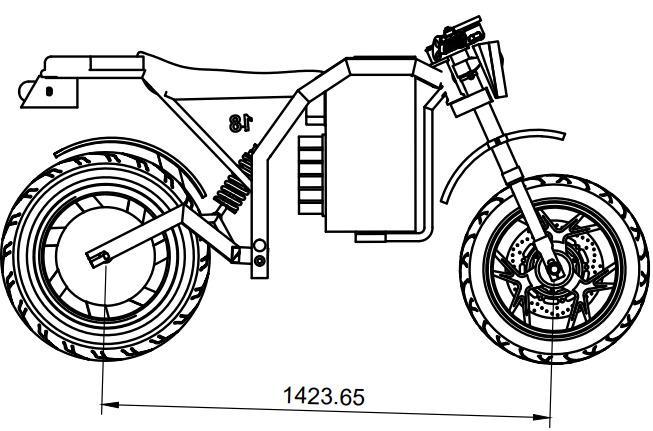
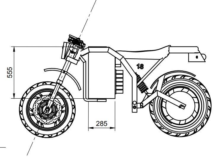
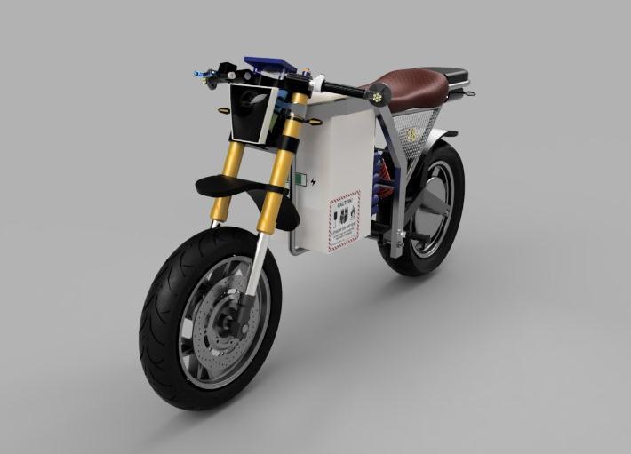
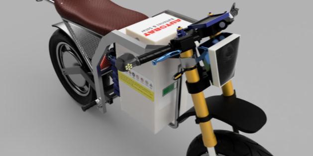
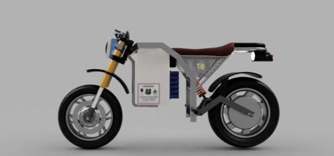
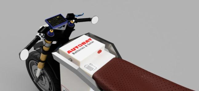
Figure 12 Bike design RHSV
Figure 13 Bike design LHSV
Figure 14 Bike design Front

2021, IRJET | Impact Factor value: 7.529 | ISO 9001:2008 Certified Journal

International Research Journal of Engineering and Technology (IRJET) e ISSN: 2395 0056

Volume: 09 Issue: 06 | June 2022 www.irjet.net p ISSN: 2395 0072
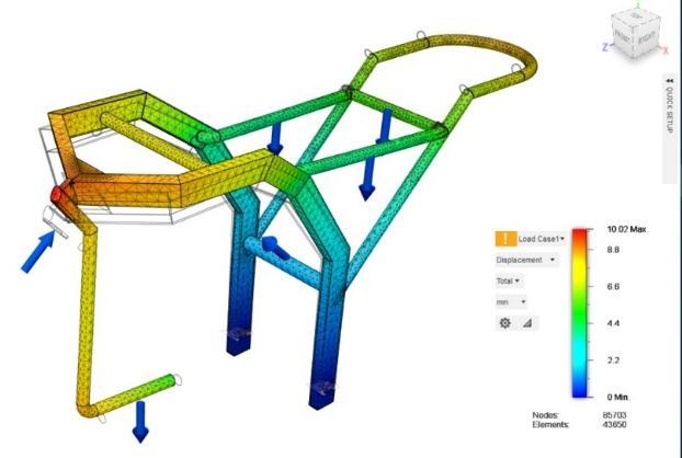
b. Maximumdeformation
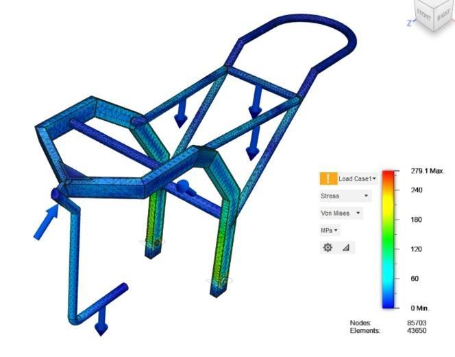
1. Swing arm a. Stress
Table 3 Table 4
Figure 21 Swing arm stress analysis
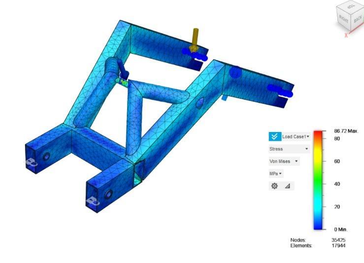
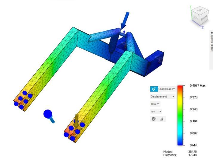
Figure 22 Swing arm deformation analysis
Table 5
Table 6
International Research Journal of Engineering and Technology (IRJET) e ISSN: 2395 0056
Volume: 09 Issue: 06 | June 2022 www.irjet.net p ISSN: 2395 0072
Table 7 Table 8
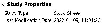
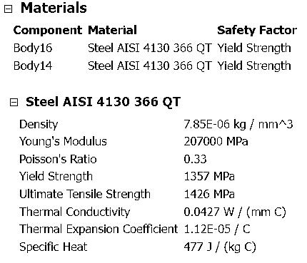
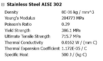
2. Suspension
Figure 23 Suspension stress analysis

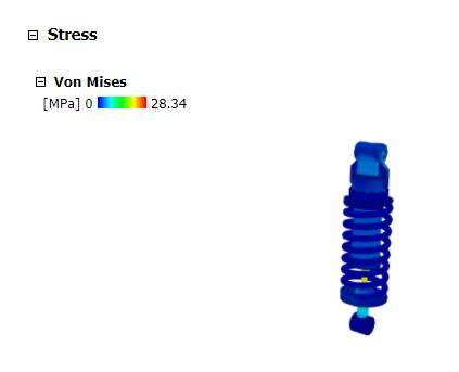
Table 9 Table 10
Table 11
2021, IRJET | Impact Factor value: 7.529 | ISO 9001:2008 Certified
Electric Vehicles differ from traditional petrol or diesel poweredvehiclesastheyoperateonelectricity,whichcan be obtained from renewable and non renewable energy sourcesunlikethelatterones,whichcanonlybepowered, by non renewable energy sources. Hence, we can drastically reduce the carbon footprints by using renewable energy sources for electricity generation such as solar, wind, water, etc. Here we have designed electric vehicle that is battery operated. In this project, our main motive was to design a battery charging circuit and Controllercircuitforbatterybasedelectricvehicle.Inthis semester, we have successfully completed the simulation anddesigningpartofourFinalyearproject.
The objective of this project is to provide a clear and thorough presentation of theory and practical knowledge ofconveyorbelts,buoyancyandmotor drivingcircuits.To achieve this objective, the group members by no means have worked alone as these ideas have been shaped by comments,suggestionsandacceptancegivenbyProf.(Dr.) Laxmikant Mangate, Department of Mechanical Engineering. We are thankful to him for his guidance, supportandinputsinthiscourseprojectwithoutwhichit would not have been a success. We are thankful to Prof M.B. Chaudhari, Head of the Department of Mechanical Engineering for his support and for the addition of such kind projects to our curriculum. We express our sincere thanks to the management of Vishwakarma Institute of Technology, Pune for allowing us to carry out such educational projects. We express our feelings and respect towards our parents, without their blessings, help and motivationthisprojectcouldnothavebeencompletedand wouldhavebeenjustadreamforus.Wearethankfultoall those whom we might have inadvertently failed to mention here but have a positive contribution to the successfulcompletionofthisproject.

[1] DESIGN AND DEVELOPMENT OF ELECTRIC MOTORBIKE; Srinivas Mutyala, M.Tech(Cad/Cam); International Research Journal of Engineering and Technology(IRJET)Volume:06Issue:12|Dec2019
[2] Design And Prototype Production Of An Electric Motorcycle; Shubham Devendra Saxena, Rushabh Vikas Sakale, Abdullah Shafiq Salmani, Prof.H.N.Deshpande, Shoheb Ashraf Shaikh; 2018 JETIROctober2018,Volume5,Issue10
[3] DESIGN AND MANUFACTURING OF ELECTRIC BIKE WITH SWITCHABLE AWD TRANSMISSION; Vivek Meshram, Shubham Takalkar, Apul Mohan, Siddesh Patil,Suman Kurup; International ResearchJournal of
International Research Journal of Engineering and Technology (IRJET) e ISSN: 2395 0056
Volume: 09 Issue: 06 | June 2022 www.irjet.net p ISSN: 2395 0072
Engineering and Technology (IRJET) Volume: 08 Issue:06|June2021
[4] Design and Construction of an Electric Motorcycle, Emma Drummond, Peter Condro, Ben Cotton, Carlos Cox,AdamPinegar,KyleVickery
[5] DesignandFabricationofElectricMotorcycle,KunalD Topiwala, Mr. Chitan Patel, Sufiyan Ansari, Himanshu Patel
[6] Battery Management Systems in Electric and Hybrid Vehicles, Yinjiao Xing, Eden W. M. Ma, Kwok L. Tsui andMichaelPecht
[7] DESIGN AND DEVELOPMENT OF ELECTRIC MOTORBIKE,SrinivasMutyala.
[8] Building an Electric Motorcycle: Design and Construction of a Zero Roadside Emissions Vehicle, MaxwellK.Becton
© 2021, IRJET | Impact Factor value: 7.529 | ISO 9001:2008 Certified Journal | Page2457