International Research Journal of Engineering and Technology (IRJET)
e-ISSN: 2395-0056
Volume: 09 Issue: 05 | May 2022
p-ISSN: 2395-0072
www.irjet.net
SUBSTATION MONITORING AND CONTROLLING BASED ON MICROCONTROLLER BY USING IOT ARUN.J, SATHIYAN.P, MANIKANDAN .N 1 final
year student, department of electrical & electronics engineering, k.c.t Coimbatore, tamilnadu year student, department of electrical & electronics engineering, k.c.t Coimbatore, tamilnadu 3final year student, department of electrical & electronics engineering, k.c.t Coimbatore, tamilnadu ---------------------------------------------------------------------***--------------------------------------------------------------------2. Block diagram Abstract - Substations are the main structure block in a 2final
power system. Any damages in Substation negatively affect the balance of a power system. The damages are substantially being due to overfilling and hamstrung cooling. downsides of the conventional monitoring system and the biggest problem in the electricity distribution grid are utmost of the distribution are ever located in a pastoral area, where regular monitoring by mortal observation is delicate to perform due to inadequate force. Being monitoring systems aren't supported for real time operations. There are too numerous failure cases are detected every day. Not allowed for planning operation time-out. The main ideal of the real time monitoring of the health conditions of the distribution motor using IOT technology. The parameters similar as oil position, temperature, voltage and current of a transformer are covered, reused and recorded in waiters. For this purpose, we use four detectors connived with Arduino. The recorded data can be shoot using Wi- Fi module and penetrated from anywhere around the world using IOT technology using HTTP protocol. This helps in relating without mortal reliance. This helps in relating and working a problem before a failure without mortal reliance.
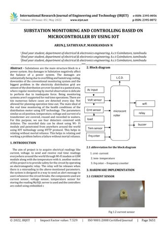
L.C.D.
Ac input Volt sensor wifi Crnt sensor
microcont roller
relay
load buzzer Tem sensor Frq cnter
1. INTRODUCTION 2.1 abbreviation for the block diagram
The aim of project is to acquire electrical readings like current, voltage. to send and receive real time readings everywhere around the world through Wi-Fi modem or GSM module along with the temperature with it. another motive of this project is to provide safety for the circuit by operating an electromagnetic relay. The relay will be releases when there is a misreading in the above-mentioned parameters. the system is designed in a way to send an alert message to users whenever the circuit breaks. the components used are current sensor, voltage sensor, temperature sensor for storing the reading MySQL server is used and the controllers are coded using embedded c
1. crnt- current 2. tem- temperature 3. frq cnter – frequency counter
3. HARDWARE IMPLEMENTATION 3.1 CURRENT SENSOR
Fig 1.2 current sensor
© 2022, IRJET
|
Impact Factor value: 7.529
|
ISO 9001:2008 Certified Journal
|
Page 3651