International Research Journal of Engineering and Technology (IRJET)

Volume: 09 Issue: 04 | Apr 2022 www.irjet.net
e ISSN: 2395 0056
p ISSN: 2395 0072
Subhadeep Kuila1, Sudhanshu Yadav2
1 School of Engineering and Applied Sciences, National Rail & Transportation Institute, Vadodara
2School of Engineering and Applied Sciences, National Rail & Transportation Institute, Vadodara
***
Abstract A new mathematical model to estimate the regenerative braking efficiency of Indian locomotives, which are already installed with the 'regenerative braking system,' is discussed here. It is demonstrated for a WAP 7 locomotive that runs on Indian tracks. This paper discusses the need of having an alternate energy recovery mechanism, (Flywheel here) in the mechanical model of the locomotive. The effect of gradient on energy savings for this new model is discussed here. The drive cycle relationships have been developed to study energy estimations on the selected route of ADI MMCT. Finally, energy savings of the model proposed is compared with the energy savings of the already existing mechanism of WAP 7.
Key Words: Flywheel, FBESS, Mathematical Model, Regenerative Braking, OBESS
1. INTRODUCTION
One of the environmentally friendly ways of transportationisrailways.Itisacriticalapproachtomeet risingtransportationdemandsinanecologicallyconscious economy.India'srailsectorremainsalargeenergyuser With a growing population and greater energy consumption, the need for rail services will continue to rise, and energy consumption will increase in tandem.1 Theenergylostastrainsreachrailstationsprovidesan obviousadditionalsourceofenergythatmaybeusedto reduce demands on electricity production facilities and improvetheoverallefficiencyoftheelectricalgridinlarge metropolitan regions. The energy lost as trains reach rail stationsprovidesanobviousadditionalsourceofenergythat may be used to reduce demands on electricity production facilitiesandimprovetheoverallefficiencyoftheelectrical gridinlargemetropolitan regions.The quantity of energy wastedeverydayinourcivilizationisstartling.Thecauses vary from inefficient systems like single pane windows in homestovitalbutinelegantsystemslikefrictionbrakeson nearlyeverymodeoftransportation. The theory of regenerative braking captures the energy expendedwhencarsusetheirbrakestoslowdown,andit providesapracticalwaytouseotherwisedissipatedenergy. Using lost energy to boost energy supply to the electrical gridwithoutincurringadditionalproductionexpensescan improvetheelectricalgrid'soverallefficiency.Theotherwise squanderedbrakingpowermaybeeffectivelyandcheaply gathered and utilized to replenish the neighbouring
value:
electricalgridbyusingelectricalgeneratorspositionedon train rails at appropriate locations to provide the decelerationforcesnecessaryforbraking.
1.1. CURRENT SCENARIO OF REGENERATIVE BRAKING IN INDIAN RAILWAYS
The Indian Railways have been particularly attentive aboutenergyconservationandefficientutilization.Electric tractionhasauniquefunctioncalled'regenerativebraking,' which converts the train's energy in motion to electric energy upon braking and giving it back to the feeder services.Thisfunctionhasbeensuccessfullyimplementedin theWAG 9,WAP 7,andWAP 5locomotiveclasses,savingup to20%andonallnewelectricalmultipleunits(EMU)that cansaveupto30%.Whilethisfunctionsavesenergy,italso extendsthelifeofthewheelsandenhancestheLocomotive's availabilityfordrivingtrains,makingelectrictractionmore cost effective. 3
Figure 1: The regeneration values of 3 Phase electric rolling stock of Indian Railways
The figure above depicts the regeneration and traction values of 3 Phase electric rolling stock used by Indian Railways in WAG 9, WAP 5, WAP 7, and EMUs (Electric Multiple Units). It could be seen that the regeneration capabilitiesofEMUsaremoresignificantthantherestofthe categoriesmentioned. Whileit isveryappreciableto note that Indian Railways has successfully achieved a regenerationsavingofabove20%onthelocomotiveclasses of WAG 9 and WAP 5, it is also crucial to increase regenerationefficiencyintheseareasclassesoflocomotives tocompensateforenergylosses 3
RailwayshavereducedSpecificEnergyConsumption(SEC) by roughly 18.9% during the previous five years through different energy conservation strategies. According to the BEE evaluation for 2014 2015, energy usage in traction applicationsimprovedby3.3percentfroma yearearlier.

Regenerative Braking in Indian Locomotives: A model involving the use of flywheel as an ESD (Energy Storage Device) in WAP-7 Locomotives
International Research Journal of Engineering and Technology (IRJET)

Volume: 09 Issue: 04 | Apr 2022 www.irjet.net
Over several years, Indian Railways has also received 87 energyconservationawards.
1.2 COMPARATIVE ANALYSIS OF REGENERATIVE BRAKING ENERGY SAVINGS: CASE OF INDIAN RAILWAYS NCR & UNITED KINGDOM SWR
We have tried to compare the case of Indian Railways' North Central Region and United Kingdom's South West Region running trains with Regenerative BrakingcapabilitiestoconcludewithwhatmeasureIndian Railwaysshouldrelyuponforachievinganexcellentenergy savingindex.
NCRhassavedover15millionpowerunitsbyrunning thesetrainswiththree phaseinductiontractionmotorswith regeneration capabilities.4 Cutting down to numbers, we have 400 electric locomotives running across NCR, out of which100haveregenerativecapabilities,andthe15million kWh saving of electricity is due to these 100 three phase inductiontractionmotorsfittedlocomotivesonly.
Morethan200electrictrainsontheSouth WestTrains networkhavehadequipmentinstalledaspartofthescheme. These trains serve Guildford, Alton, Portsmouth, Reading, Southampton, and Weymouth in the London suburbs. They'veallbeenupgradedtoincludethenewenergy saving technologies. The technique saves 50 million kWh of electricity each year, enough to power around 11,500 UK householdsforayear.5
We could conclude, from the figures below that despite having double the number of trains equipped with Regeneration capabilities, the energy saving is almost 3.5 times that of the NCR region. The track on which these figureshavebeentakenhasapproximatelythesametrack length, which Trains running in SWR Class 458 Class 444 Figure3:Proportionof3 PhaseITMlocomotivesfromNCR makes the comparison fair enough to decide what extra technologies UK's SWR uses that make it such energy efficient.Wewillbetalkingaboutthatpartinlatersections ofourpaper.
1.3 MODERN ELECTRIC RAIL VEHICLE: OVERVIEW & POWER FLOW IN WAP 7 LOCOMOTIVE
WAP 7 is the 7th generation of WAP class locomotives, where W stands for broad gauge (Wide), A stands for AC Electriclocomotive,andPforPassengerlocomotive.WAG 9 is the 9th generation of WAG class locomotives, where W stands for the same broad gauge (Wide), A stands for AC Electriclocomotive,andGforGoodsorfreightlocomotive
ThemajorcomponentsofthisWAP 7locomotivearea) Pantograph,whichcollectsthehightensioncurrent(25kV) from the contact wire, b) Voltage Regulating Equipment, wherethemaintransformer,consistsofanAutotransformer with 32 taps and a stepped down transformer with two distinct secondary windings, steps down the high OHE voltagetoalowvoltage,c)SiliconRectifiers,whichconverts thealternatingcurrentprovidedbysecondarywindingsof the main transformer is into direct current utilizing two silicon rectifiers (RSI), one each supplying to set off three
e ISSN: 2395 0056
p ISSN: 2395 0072
traction motors, d)Traction Induction Motor, which is the prime mover of the locomotive. Generally, a three phase Inductionmotorisusedastheprimarytractionmotordueto itsElectromagneticproperties.6
Figure 2: Main Components of a Modern Electric Rail Vehicle
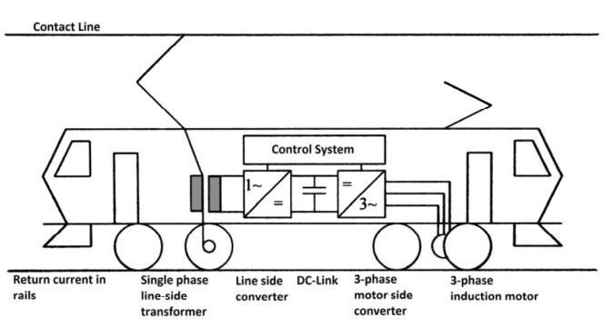
Thepowerflowthroughthelocomotivehappenswherein, the "traction sub station," a single phase step down transformer is linked to the three phase utility system, whichfeedsenergytotheoverheadline(high voltage)and therail("ground").ThepantographcapturestheACpower andisthenprovidedtothevehicle.TheLocomotiveisfitted with appropriate equipment to enable the loco pilot to manage the train's speed according to requirements by regulatingtheappliedvoltagetotractionmotors.The25KV, single phaseACpowerisgatheredfromtheOHEbyaroof mountedpantographandsteppeddownbyatransformerin typical locomotives. Before being supplied to the traction motors, this supply is converted to DC using a full wave siliconrectifierandrelatedsmoothingfilter.Thevariationof the AC input voltage to the rectifier via an on load tap changing arrangement on the primary winding of the locomotive transformer is used to manage torque and speed 7
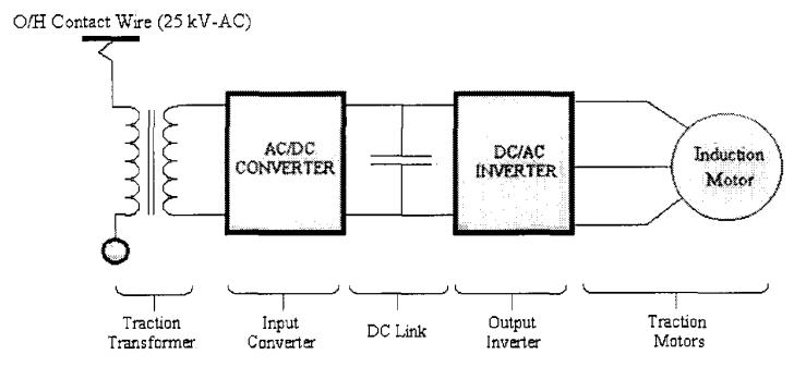
Figure 3: Simplified view of power flow in a WAP 7 locomotive
TheLocomotive'sprimarytransformerstepsdownthe25kV overheadACsupply.Itfeedsittoafrontend(line)dual4 quadrantlineconverter,whichconvertstheACtoDCusing Pulse Width Modulation (PWM) to achieve a unity power factor.Thissupplyisconnectedtoaninputsideconverter through a DC connection, which serves as an energy reservoir. The VVVF Converter transforms the DC supply
© 2022, IRJET | Impact Factor value: 7.529 | ISO 9001:2008 Certified Journal | Page3828
International Research Journal of Engineering and Technology (IRJET)

Volume: 09 Issue: 04 | Apr 2022 www.irjet.net
into three phases, subsequently delivered to three phase tractionmotors.TheoutputoftheDriveconverter(inverter) is a VVVF (Variable Voltage Variable Frequency) supply, whichaidsinadjustingthestartingandoperatingtorquesof three phasetractionmotorstomeettrafficneeds.
1.4 BRAKING OF A WAP-7 LOCOMOTIVE
Intractionsystems,therearetwoformsofbraking:dynamic (electric)brakingandclassicfrictionbraking.Theproduced current is used for regenerative braking when a traction motoristransferredtoageneratorfordynamicbraking.This brakingishelpfulforheavy hauldiesel electriclocomotives operating on routes with significant downgrades. When regenerative braking is used to decelerate the train, the currentintheelectricmotorsisreversed.8
In a Conventional Friction Brake, the hydraulic mechanismmainlydrivesthebrakingsystem.Itconsistsofa primary,ormaster,cylinderfilledwithfluidandlinkedtoa secondary or slave cylinder. When the brake pedal is depressed,apistoninthemastercylinderdepresses,forcing fluidthroughthecircuitandintotheslavecylindersateach wheel, which push the pistons to apply the brakes effectively. This system has improved over time with advancements like disc brakes, floating and multi piston callipers,andpowerbrakes,makingbrakingmoreeffective and comfortable for the driver, particularly with today's engines'moresignificantpoweroutputs.9
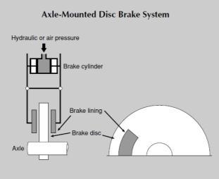
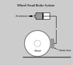
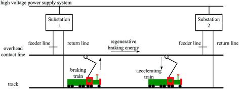
Let us now look at the regenerative energy recovery mechanismusedinLocomotiveandthesubsequentenergy usageutilizedbyanacceleratingtrainonthesamecontact line.Itcouldbeseenthattheenergyrecoveredbyonetrain issentbacktotheOHElineforotheracceleratingtrainsto feeduponit.
Figure 5: Block diagram of energy recovery and usage on same OHE line by an accelerating train
In Regenerative Braking of a WAP 7 locomotive, if we get energybackfromtheTractionmotor,itactsasagenerator,
e ISSN: 2395 0056
p ISSN: 2395 0072
generatingelectricalenergyfromthekineticenergywhen braked upon. So, in the case of regenerative braking, and InductionMotoractsasanInductionGenerator.Induction MotoractsasanInductiongeneratorwhentheslipbecomes negative,i.e.,whentheslipofmotorislessthan0,thenkicks in the regenerative braking capability of the motor, and whentheslipisgreaterthan0.Themotortractioncapability actsuponthedevice.
NN slip N
SR S
NS issynchronousspeedandNR isspeedofrotor
Ineasywords:
Slip>0,NS>NR:InductionMotor Slip<0,NS<NR:InductionGenerator
Whenthebrakesareapplied,theNSisreducedtosucha levelthatthevalueofNSislessthantheNR.Thus,themotor acts as a generator, generating electricity from the mechanical shaft movement due to inertia. NS could be alteredasitdependsuponthefrequencyoftheAlternating Current supplied to the motor. The slip could be changed whenbrakingisneededtomakeitlessthan0. 10
By reducing the frequency of AC supply, we could suddenlyreducetheNSorsynchronousspeed,butNRorthe rotorspeedwouldnotreducesuddenlyduetotheinertiait has gained by rotating. This is how the NS or the slip is changedformakingthemotorbehaveasagenerator.Weuse VariableFrequencyDrives(VFD)tochangethefrequencyof the AC being provided to the motor. A variable frequency drive(VFD)isamotorcontrollerthatcontrolsthefrequency andvoltageofanelectricmotor'spowersupply.
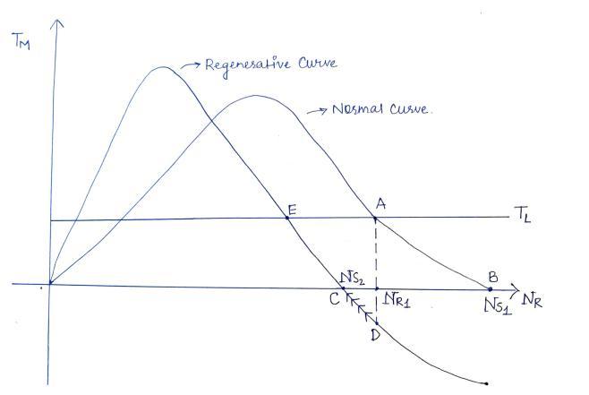
Assoonastheslipbecomesnegative,themotor'storque also becomes negative, i.e., it reverses the direction of appliedtorque.Thetorqueofthemotortriestoadjustitself bychangingfromnegativetopositive,butwhenthevalueof torqueinitsquestofbecomingpositivetouchesthevalueof 0,i.e.,zerotorque,thesupplyofcurrentiscutdowntothe motor, which forces the motor to stop. We receive excess energy as an energy saving from this regeneration mechanism.Thesamecouldbeunderstoodfromthegraph givenbelow
Figure 6: Torque and Speed Characteristics of an Induction motor
© 2022, IRJET | Impact Factor value: 7.529 | ISO 9001:2008 Certified
International Research Journal of Engineering and Technology (IRJET)

Volume: 09 Issue: 04 | Apr 2022 www.irjet.net
2. MATHEMATICAL MODELING OF WAP 7TRAINS
ThemathematicalmodelforWAP7locomotivedevelopedin thisresearchusestheequationsofmotion.Thetractiveeffort Ftrac.,trackresistanceforceTres,andthegradientforceTgrad are considered as the three main operating force on the train’sbody.
= ·a= (1)
Meff istheeffectivemassofthetrain,Faisthenetresultant forceacceleratingthetrain.
2.1. Equations governing train dynamics
The motion of train is majorly governed by the newtons third law of motion. The effective mass of the train is dependentuponthemassoflocomotives,taremassofthe carriagesandthemassofthepayload.
(2)
Here, Mloco is the mass of the locomotive, Ncarr Is the total numberifthecarriages,Mtareisthetaremassofthecarriage andMpayload ispayloadpervehicle.Byusing(1)and(2)we canfindtheaccelerationas:
(3)
Tractive effort is the net force applied by the locomotive parallel to the direction of motion. The tractive effort is constrainedbythemotorcurrentlimitsandthemechanical restriction. Valuesofthestartingeffort,continuoustraction effort and braking effort is taken from the official documentation A train's track resistance is its velocity dependent resistance to motion. The semi empirical Davis equationiscommonlyusedtocalculateresistance.
= + + (4)
DA ,DB ,DCarethecoefficientsforthevariousfrictionalforce Effectofgradientwithθastrackgradientcalculatedas:
(5)
2.2. Train Parameters
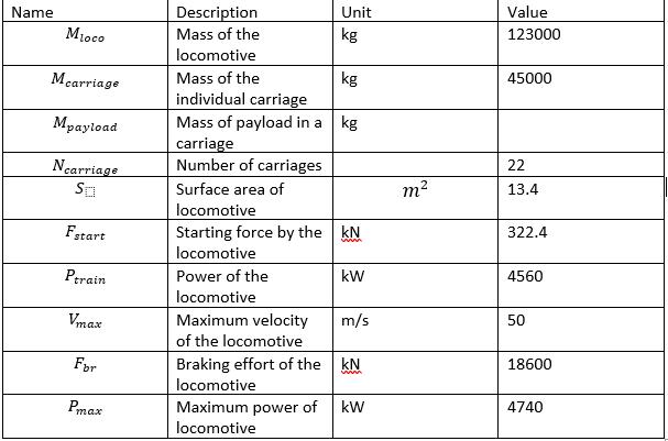
ThefocusofourstudyistheWAP7locomotive,forthatwe havechosenShatabdiExpressthroughtherouteADI MMCT (Ahmedabad Jn Mumbai Central) would be used. This convoyischosenbecauseitisoneofthefastestconvoyson one of the busiest sections. The data used is given in the tablebelow.
e ISSN: 2395 0056
p ISSN: 2395 0072
2.3. Drive Cycle and Energy Estimation
A driving cycle is necessary to evaluate the train's energy consumptionbecausetheefficiencyofahybridpowertrainis highly dependent on the duty cycle as well as route parameters WeusedthedataavailableontheAhmedabad MumbairouteofShatabdiexpressforrecreatingthedriving cycleinsimulation.Therecreateddrivingcycle'sdistances andtimeweretestedandvalidatedagainstfiguresgivenby erail.in Table(2)belowshowstheinputusedforthedriving cycle,whichshouldbereadfromlefttoright
Sr no. Station waitin g time (sec)
Trave l Time (sec)
Distance (m)
1 Ahmedaba d 0 2040 45000
2 Nadiad 120 1020 19000
3 Anand 120 1800 35000
4 Vadodara 300 2820 71000
5 Bharuch 120 2760 58000
Surat 300 3840 93000
7 Vapi 120 5220 140000 8 Borivali 180 3420 30000 9 MMCT 0
Table 2 Route data for drive cycle
The track's gradient data is not given, but the model can handlegradients,allowingbroaddependenciesonuniform gradientstobedemonstrated.
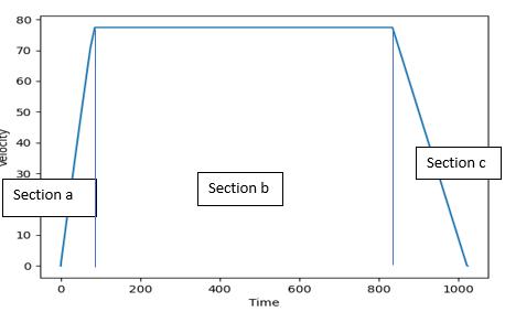
Based on a modified versionof the velocity stepapproach (Ref.JongJ C,ChangS),drivingcycleiscreated.Thedriving cycle is set up to correspond to the distance and time requirements listed in data table provided above. The approachismodifiedbyintroducingaconstantvelocitypart inthesimulationthathelpsinmeetingthetimeframeforthe given distance. There are three phases to each driving section: acceleration, constant velocity motion, and deceleration as depicted in the figure given below. The acceleration (section a), constant speed (section b) and decelerationtrajectory(sectionc).
© 2022, IRJET | Impact Factor value: 7.529 | ISO 9001:2008
International Research Journal of Engineering and Technology (IRJET)

Volume: 09 Issue: 04 | Apr 2022 www.irjet.net
2.4. Implementation
e ISSN: 2395 0056
p ISSN: 2395 0072
Figure 7: Drivecycle,showingthethreesections

Accelerationstartsateachstationandestablishesaconstant speed, while the deceleration trajectory (section c) is dependentupon,thenextarrivingstation,brakingpowerand safetyandcomfortrestrictions.Distancecoveredinall the three phases are computed concurrently as the velocity is increased in each step in an iterative manner. As the net distance travelled (area under the velocity time curve) matchesorexceedsthedrivinglengthofthegivensectionwe stop the acceleration. Then the train travels at a constant speed for a pre decided length, and then starts to deaccelerateasitreachesthecalculatedbrakingdistance.As a result, the time criteria are met precisely, whereas the distancesarenearaccurate.
After using equation 3 for determining acceleration, we movedontodeterminingvelocity,formulausedforthatis.
(6)
InPython,numericalmodelincorporatingalltheequations discussedabovewascreated.Drivingcycleiscomputedafter taking in the input of route profile, train parameters and otherconstraints.Thevelocity stepalgorithmisappliedat everysectionoftrack.Continuouscomputationisperformed to calculate the distance traveled and braking distance required.Foreachvelocitystep,itstartswithcalculatingthe force requiredtoovercome theforce of friction and other resistances. Then it moves onto calculate the resultant accelerationusingtheequation(3)providedabove.Further it updates the velocity and acceleration using equations 6 and7.Nextitchecksthebrakingdistanceandbrakingtime requiredtostopthistrain,afterthisthetimeforwhichthe trainwillrunataconstantspeediscalculated.Thedistance travelledinallthree(accelerating,constantspeed,braking) phasesisaddedup.Thisprocessisrepeateduntilthesumof distancesmeettheprescribeddistanceofthesection.After generating the drive cycle all time dependent kinematic variables and forces are calculated, and the energy consumptionisevaluatedduringpostprocessingusingthe equations10and11.

Below is the flow chart depicting the outline of the whole processimplementedtoobtainresults.
Thedistancecoveredwasupdatedusingfollowing equation.
(7)
Thedatavitaltothissimulationisthepowerconsumption throughoutthejourney.Theinstantaneoustractivepower requiredbythetrainisdeterminedby:
(8)
Theenergyconsumptionandenergyrecoveredbythe regenerativebrakingarewhatwe'reinterestedin.The followingistheformulaforenergy.
(9)
Theenergyconsumptionduringthetractionwillbe calculatedbyusing: (10)
Theenergyrecoveredduringthebrakingoftrainwillbe calculatedusing: (11)
3. RESULTS
Below are the results and graphs obtained from the simulation This simulation estimates the total energy consumed by the train in traction, we can use this to computetheenergytakenfromsubstationusingequation 12.
(12)
HereE_trac^Acisthetotalenergytakenfromthesubstation, E_trac^ isthetractionenergyobtainedfromequation 10. η_1istheinductionmotor’sefficiencytoconverttheinput electrical energy to output traction energy. Similarly, simulation also produces the cumulative braking energy producedduringdrivecycles.
Wecanusethistoobtainthenetamountofenergyarriving attheflywheelbyusingequation(13).
Figure 8: Basic modules and steps used in Python modelling
International Research Journal of Engineering and Technology (IRJET)

Volume: 09 Issue: 04 | Apr 2022 www.irjet.net
Recovered energy is equal to the multiplication of energy storedinflywheelwithflywheel’sefficiency.
(14)
In the equation (13) is the energy reaching the flywheel energy storage system (FESS). Multiplied with efficiency of the FESS we obtain that is the energystoredintheFESS.Sincetheenergymustagainpass throughtheinductionmotortoreachthewheelsofthetrain, theenergyrecoveredisequaltotheenergycollectedbythe FESSmultipliedby .
(15)
Wealsoobtainthevalueofefficiencygain,whichisdefined astheratioofenergyrecoveredtotheratioofenergyspent through out the trip (16). As well as the value of energy recovery efficiencywhichisdefinedasthe ratioof energy recoveredtobrakingenergy(17).
(16) (17)
Power Time curve
e ISSN: 2395 0056
p ISSN: 2395 0072
Peakaccelerationpowerforthisrunis4.79Megawatts, peakpowerduringdeaccelerationis 1.54Megawatts.
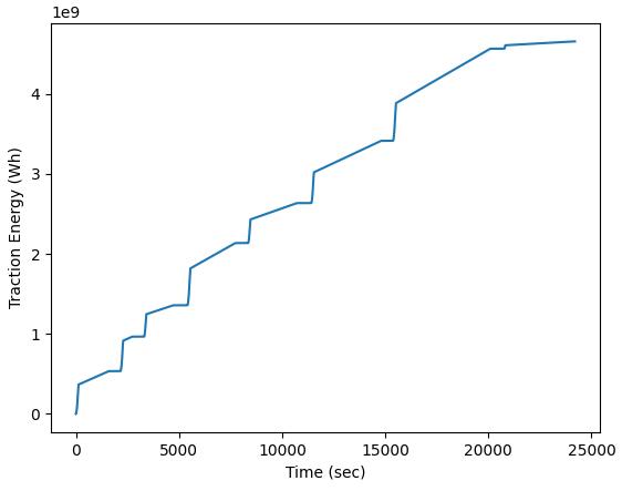
Traction Energy Time curve
3.1. Results for zero gradient
Graphs below of passenger stock (18 LHB II Ac Coaches) beingpulledbytheWAP7locomotiveontherouteshownin table1.
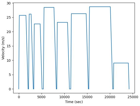
Velocity Time Curve
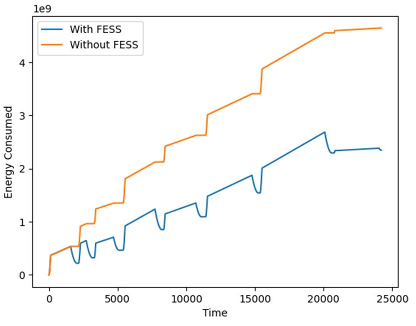
Total consumption of energy in whole travel time is 4.65×10⁹ watt hrs
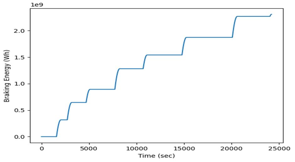
Braking Energy Time curve
Themaximumvelocityattained28.72m/s. Acceleration Time curve
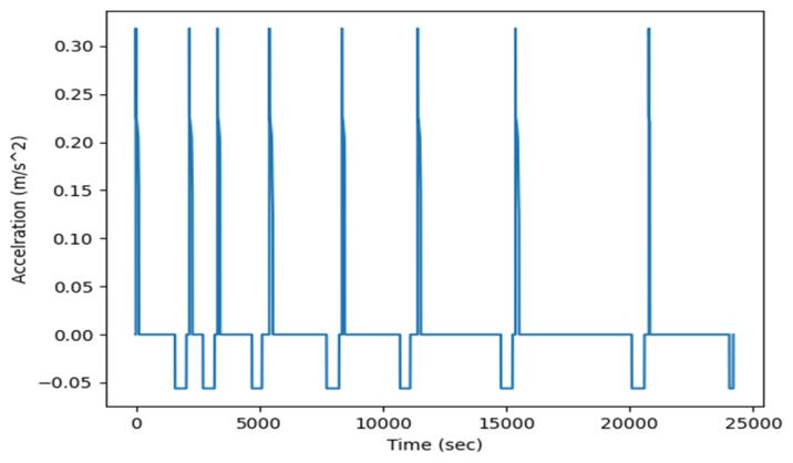
Peak acceleration for this run is 0.31m/s2, peak deaccelerationis0.051m/s2
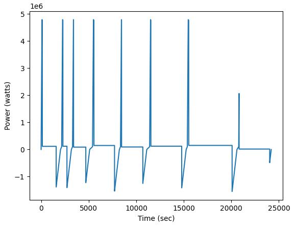
Total consumption of energy while braking is 2.304*109 watt hrs.
Tablebelowshowsthevariouscombinationsofpassenger stock being pulled by the WAP 7 locomotive on the route shown in table 1. The value for the efficiency of induction motor is taken as 0.88, and the efficiency of Flywheel as0.90.
© 2022, IRJET | Impact Factor value: 7.529 | ISO 9001:2008 Certified Journal | Page3832
International Research Journal of Engineering and Technology (IRJET)

Volume: 09 Issue: 04 | Apr 2022 www.irjet.net
Table 3: Estimated recovered energy for various train configurations on route shown in table 1
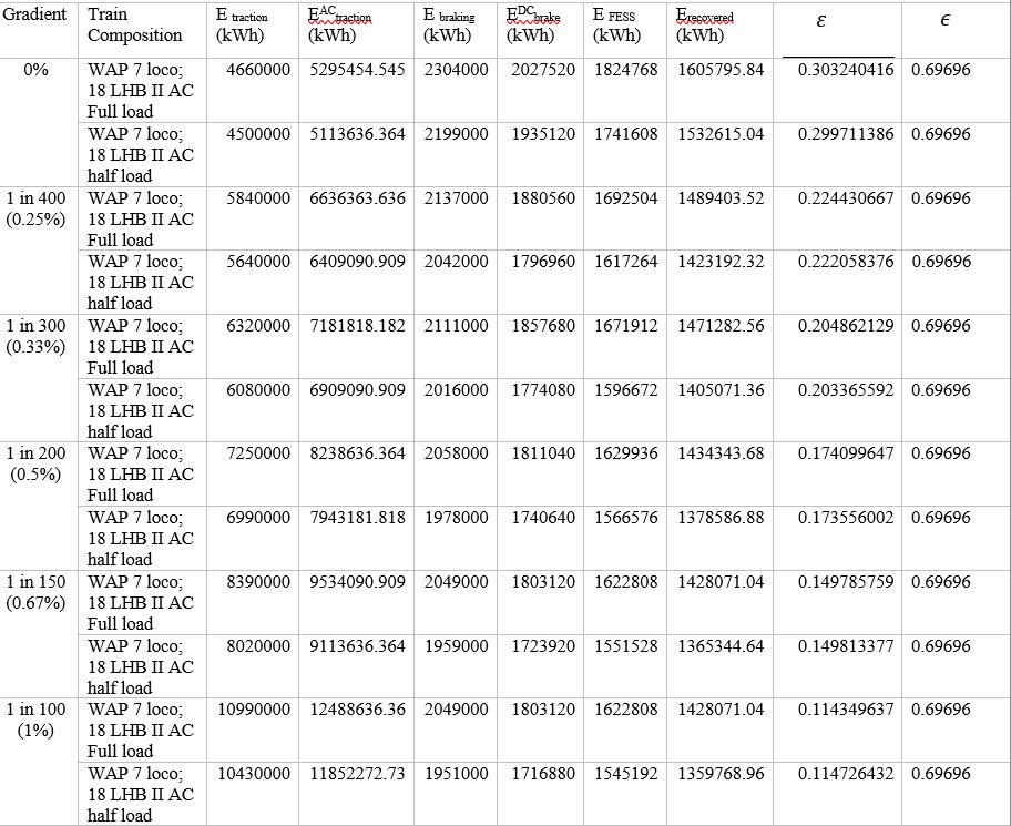
Foratrainconsistingof18fullyloadedLHBIIACcoaches the total energy spent in traction is 5.29×10^6 kWh. The brakingenergygeneratedis2.304×10^6kWh.Totalenergy that can be recovered if on board FESS is used 1.6×10^6 kWh,whichisaround30%oftotalenergysuppliedforthe traction. Similarly, for all other composition of the stock valueofεrangesfrom0.29to0.31.Whereasthevalueofϵis constantforallthecompositions.
e ISSN: 2395 0056
p ISSN: 2395 0072
Totalenergyconsumedoverthetriprepresentedbyorange curveis4.65×10^6kWhandforthebluecurveis2.36×10^6 kWh.EstimatedenergysavingsbyusingFESSinthiscaseis 2.29×10^6kWh.
4. CONCLUSIONS
The results show that utilizing the FESS can save a significantamountofenergy.Theestimatedenergysavings varieddependingonthetrack,payload,numberofcarsper train, and kind of FESS. The net recovered energy ranges from29 31%ofthetotalenergyconsumed.Withincreasing gradient,theenergysavingsfromaflywheeldecreaseddue tolessrequirementofbrakingonup terrain.
The feasibility of a FESS for decreasing energy usage in passenger rail transportationsystemsisconfirmed in this study.Thetechniqueandresultscanbeapplicabletovarious rail routes, eveniftheresultswereachievedfora specific route.
5. REFERENCES
[1] Douglas, H.; Roberts, C.; Hillmansen, S.; Schmid, F. An assessmentofavailablemeasurestoreducetractionenergy use in railway networks. Energy Conv. Manag. 2015, 106, 1149 1165, Available at: http://dx.doi.org/10.1016/j.enconman.2015.10.053
[2]AsegidBelayKebede,GetachewBiruWorku,Aresearch on regenerative braking energy recovery: A case of Addis Ababa light rail transit, Science Direct, 2021, Available at: https://www.sciencedirect.com/science/article/pii/S25901 16821000151
[3]EnergyScenario,RAILWAYSSYSTEMFORANALYSISOF VIDYUT ENERGY, [online], no date, Available at: https://www.railsaver.gov.in/en_scenario.html
[4] Ashraf Jamal, 'Regenerative braking helps Railways to save energy, money, Times of India, 26 September 2011 [online], Available at: https://timesofindia.indiatimes.com/city/allahabad/regene rative braking helps railways to save energy money/articleshow/10131180.cm
[5] South West trains complete £2.2M investment in RegenerativeBrakingsystemtodrivegreenertrains,News Releases,Stagecoach,29March2012[online]
[6] M Tulbure, R Both, Models for AC locomotive RegenerativeBraking,IEEEXplore,[online],nodate
[7] How Electric Locomotives (Electric Trains) Work, StudyElectrical,2019,[online]
[8]VladRadu,UnderstandingConventionalFrictionBrakes and the Regenerative Braking System, Autoevolution, 4 October 2020, https://www.autoevolution.com/news/understanding conventional friction brakes and the regenerative braking system 149614.htm
[9] Regenerative Braking of Induction Motor, Electrical Yatra,[Blog],nodate
[10] Regenerative Braking of 3 Phase Induction Motor, Lecture28,ElectricalYatra,18September2018
