Tostudyseismicperformanceofbuildingwithand withoutshearwallsrestinghillyterrain.
1.2 Method of Analysis
Key Words: Seismic Performance, Shear Wall, Response Spectrum Analysis, Storey Displacement, Base Shear, Storey Drifts.
International Research Journal of Engineering and Technology (IRJET) e ISSN: 2395 0056 Volume: 09 Issue: 02 | Feb 2022 www.irjet.net p ISSN: 2395 0072 © 2022, IRJET | Impact Factor value: 7.529 | ISO 9001:2008
Raghavendra B U1 , B.P. Annapurna2 1PG Student UVCE, Civil Engineering Dept, Bangalore University, Bengaluru, India 2Professor, UVCE, Civil Engineering Dept, Bangalore University, Bengaluru, India ***
Tostudytheeffectivenessofdifferentshearwalls configurationsonseismicactionofbuildingsresting onhillyterrainsuchasStep back.
Seismic Performance and Shear Wall Position Assessment of the Buildings Resting on Sloping Ground
1. INTRODUCTION
Tocomparetheeffectofpositioningofshearwalls onseismicperformanceofbuildingonhillyterrain
To evaluate the seismic parameters such as base shear,displacementandstoreydriftofthebuilding restingonSlopingground.
Seismicanalysisisamajortoolinearthquakeengineering thatisusedtounderstandtheresponseofbuildingsdueto Response Spectrum Analysis to seismic excitations more simply. It is a part of structural analysis and a part of structural design where an earthquake is prevalent. The seismicanalysisofallbuildingsiscarriedbytheResponse spectrummethodasperIS:1893(Part1):2016.
Certified Journal | Page607
1.1 Objectives
Shear Wall:Shearwallsaretheoneofthemostcommonly usedlateralloadresistingstructuralunitsystem.Shearwall has very high stiffness which can be used to resist huge gravityaswellaslateralloads.Thelateralstiffness,strength, andductilityaswellastheresistingseismicloadscarrying capacityofthebuildingcanbeenhancedbywell designed and detailed RC Shear. RC Shear walls have higher lateral shear force carrying capacity as well as bending capacity under lateral loads. For the buildings on hilly terrain, the columnsheightbelowplinthlevelaredifferentwhichaffects the behaviour of the building during an earthquake takes place.Hencetoimprovetheseismic performanceofshear wallsplayaveryimportantrole.So,itisanessentialtostudy the positioning of shear walls on seismic performance of buildingssituatedonthehillyareas.
Abstract In various parts of India, the ground is not flat and the lack of plain ground in hilly areas obliges construction activity on sloping terrain resulting in various significant buildings such as RC framed structures resting on hilly slopes. In such areas the constructing Structures by clearing the site, making it flat becomes uneconomical In this present study using ETABS.v19 software, A group of buildings configurations is analyzed using Response Spectrum Method (namely Step Back configuration) with different ground Sloping ground i.e., 15°, 20° and 25° with horizontal. These group further studied with 8 different Shear wall locations namely Shear wall at core, Shear wall at periphery of Sloping Side also along all 4 sides etc., By performing analysis Dynamic response of these buildings, in terms of Base Shear, Maximum Story displacement and Story Drifts Ratios is presented, and results are compared within the considered configuration. At the end, an appropriate building configuration to be used in Sloped terrain areas is recommended.
Tostudytheseismicbehaviourofbuildingsresting onslopingterrainwithdifferentslopingangles
The economic progress and fast urbanization in the hilly region have accelerated infrastructure development. Because of this, the inhabitants in the hilly terrain have increased rapidly. Therefore, there is demand for the constructionofmulti storeybuildingsonhillyterraininand aroundthelocality.Sincelevelorflatlandinhillyregionsis veryinadequate,thereisaninsistentdemandtoconstruct buildingsontheslopedground Therefore,theconstruction ofmulti storeyReinforcedConcreteFramestructuresona sloped terrain is the only possible choice to put up increasingdemandforresidentialandcommercialpurposes On hilly terrain, the buildings constructed are typically irregular,torsionalcoupledandhence,vulnerabletosevere damagewhensubjectedtoSeismicgroundmotion.Themass andstiffnessofthesebuildingsvariesalongtheverticaland horizontal planes, which results in the different centre of mass and rigidity on various floors, hence they demand analysisfortorsional,inaddingtolateralforcesunderthe actionofearthquakes.Analysisofbuildingsconstructedon hilly areas are unlike to that of buildings on the flattened groundbecause,thecolumnofhillbuildingrestsatdifferent levelsontheslopingground Duringearthquakethecolumn whichareshort,i.e.,shortcolumnsattractmoreenergyand enduresdamagewhensubjectedtogroundmotion.

BUILDING CONFIGURATION
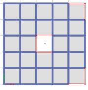
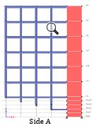
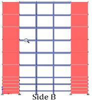
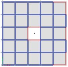
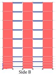
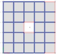
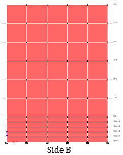
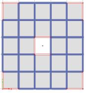
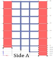
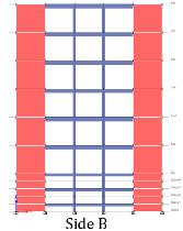
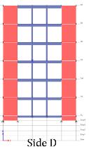
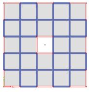
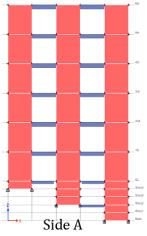
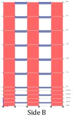
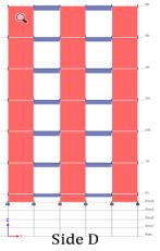
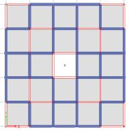
below FortheanalysisM30 gradeconcreteandFe415gradesteelareused Sl.No. PARTICULARS SPECIFICATIONS 1 No.ofstorey 6 2 Baseplan 15mx15m 3 Storeyheight 3m 4 Depthoffoundation 1.5m 5 Typeofsoil Hard 6 Columnsize 300mmx450mm 7 Beamsize 300mmx450mm 8 Slabthickness 150mm 9 Shearwallthickness 200mm,150mm Fig 1: C0 Fig 2:C1 Fig 3: C2 Fig-4: C3 Fig 5: C4 Fig 6: C5 Fig 7: C6 Fig-8: C7 SBC0 Withoutshearwall SBC1 ShearwallatInternalCore SBC2 ShearwallatInternalCore&cornersofsideB SBC3 ShearwallatInternalCore&corners+middleof sideB SBC4 ShearwallInternalCore&alongthesideB SBC5 Shear wall at Internal Core & corners of all 4 sides
areasunderconsiderationfor thepresentstudy
2.
The
International Research Journal of Engineering and Technology (IRJET) e ISSN: 2395 0056 Volume: 09 Issue: 02 | Feb 2022 www.irjet.net p ISSN: 2395 0072 © 2022, IRJET | Impact Factor value: 7.529 | ISO 9001:2008 Certified Journal | Page608
ThemodelconsistsofaG+5storeyRCCbuildinghavingfive baysineachdirection,eachbayishavingawidthof3m.The story height for each floor height is kept as 3m. The Step backmodelsareanalysedonhillyterrainonthreedifferent slopes namely 15:,20: and 25:. Under each sloping angle, further 8 models are depending upon the shear wall locations. framesonhilly isasshown
International Research Journal of Engineering and Technology (IRJET) e ISSN: 2395 0056 Volume: 09 Issue: 02 | Feb 2022 www.irjet.net p ISSN: 2395 0072 © 2022, IRJET | Impact Factor value: 7.529 | ISO 9001:2008 Certified Journal | Page609
SBC6 ShearwallatInternalCore&corners+middleof all4sides SBC7 ShearwallatInternalCore&cornersofinternal frames&Exteriorframesonall4sides
3. LOAD CALCULATIONS
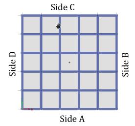
It is observed that, along X direction, there is a reduction of 72.51% for 15: slope, 66.85% reductionfor20:slopesand64.63%for25:slopes inmax.storeydisplacementfromSBC0toSBC7. ,alongY direction,thereisareductionof80.42% for15:slope,67.62%reductionfor20:slopesand 64.63%for25:slopesinmax.storeydisplacement fromSBC0toSBC7.
Max.storeydisplacementalongy directionismore thanthatofX direction
ItisalsoobservedthatalongXdirection,compare toY directionjustbyintroducingoftheshearwall at core, there is huge reduction in max storey
ItisseenthatfromSBC0toSBC7,themax.storey displacementdecreasesinbothdirections As the Slope of ground increases the max storey displacementwillalsoincreases.
AutomaticallytakenbyETABS Table 1 SuperImposedDeadLoad,SIDL SuperImposedDeadLoad,SIDLasper IS875(part 1) SIDLonIntermediateFloors i) 50mm thick mortar for flooring 1.15 kN/m2 ii)CeilingPlastering(say8mm) 0.176 kN/m2 iii)Floortilesof12mmthick 0.12 kN/m2 Total Load on Floor exceptforTerrace= =SIDL 1.446 kN/m2 SIDLonTerrace
Table 2 LiveLoadasperIS:875(part 2) LiveLoadasperIS:875(part 2) 1) Live load on all slabs exceptterrace 2 kN/m2 2) For Terrace (access is 1.5 kN/m2 provided) Table 3 SeismicLoadingasperIS1893:2016 Seismic Loading as per IS 1893:2016 SeismicAnalysisTerms 1.SeismicZone IV 2.ZoneFactor,Z 0.24 3.SiteType Type1 For Hard Soil as perTable4 4.ImportanceFactor,I 1.2 From cl.7.2.3 and Table8 5.System SMRF 6. Response Reduction Factor,R 5 aspercl.7.2.6and Table9
4. RESULTS and DISCUSSIONS
7. % of the Imposed load to be considered in SeismicWt. 25% as per cl. 7.3.1 and Table10 8.MethodAnalysis ResponseSpectrumAnalysis
Maximum Storey Displacement:
Dead load
Thedensityofwaterproofing= 16 kN/m2 Load intensity of Waterproofingcourse= 1.28 kN/m2 ii)CeilingPlastering(say8mm) 0.176 kN/m2 TotalLoadonTerrace= 1.456 kN/m2
Theabovetableshowstypicalrepresentationofmodelswith locationofShearwallsismodelledwith15:slopes.Similarly, theanalysisisdoneforthedifferentlocationsofShearwall for models with 20: and 25: slopes. 15: slope models namely15SBC0to15SBC7,20:slopeshasmodelsnamely 20SBC0to20SBC7and25:slopeshasmodelsfrom25SBC0 to25SBC7.Theactualnumberofmodelsare24withthree differentslopingangles.
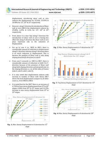
For up to case 4 i.e., SBC0 to SBC3, there is considerableamountofreductionindisplacement alongX directionwhereasalongY directionthere is no much reduction in displacement. This is because the position of Shear wall is only along slopingdirection(X direction)atsideB
© 2022, IRJET | Impact Factor value: 7.529 | ISO 9001:2008 Certified Journal | Page610
Fig. -2:Max.StoreyDisplacementinY directionfor15: slope
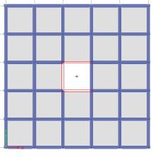
Fig. 4:Max.StoreyDisplacementinX directionfor20: slope
displacement, introducing shear wall at core reduces the displacement by 33.54%, 21.03% & 18.48%for15: ,20:&25:respectively.
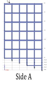
Fig. 3:TopStoreyDisplacementinX&Y directionfor15: slope
From above it is clear that along Y direction the introduction of shear wall at core is having less effect butalong Xdirection theshear wall atcore plays important role in the reduction of Displacement.
From case 5 onwards i.e., SBC4 to SBC7, there is considerable amount of reduction in both X & Y direction because of the presence of Shear wall alongbothslopingdirectionandperpendicularto theslopingdirectioni.e.,onallthesidesofframes (sideA,sideB,sideC,sideD). It is also noted that displacement reduces with increase in number of Shear wall. Hence SBC7 showstheleastdisplacementcomparetoallother casesi.e.,fromSBC0toSBC6 ItisnotedthatfortheSBC7thereisanincreaseof 6.735%ofmaxstoreydisplacementfrom15:to20: slopes,6.98%from20:to25:slopesand14.19% increase in max storey displacement from 15: to 25:slopes.
International Research Journal of Engineering and Technology (IRJET) e ISSN: 2395 0056
Fig. 1:Max.StoreyDisplacementinX directionfor15: slope
However,alongY directionbyintroductionofShear wall at core (SBC1) the displacement reduces by 29.08%, 4.29% & 0.2% for 15:, 20: & 25: respectively.
Volume: 09 Issue: 02 | Feb 2022 www.irjet.net p ISSN: 2395 0072
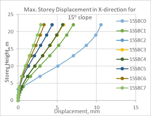
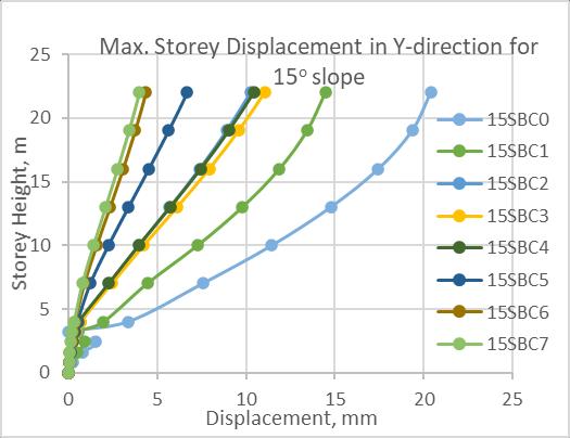
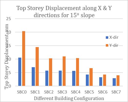
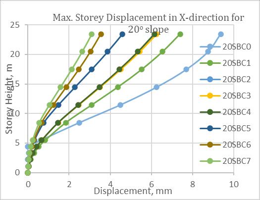
Fig. -8:Max.StoreyDisplacementinY directionfor25:
Base Shear Reactions: Fromabovefig, AstheSlopeofthegroundincrease,theBaseShear ofthebuildingalsoincreases(Fig 10to12)
BaseShearforbuildingwithoutaShearwallisless comparedtothatofbaseshearwitha Shearwall, thisisduetotheintroductionofShearwalls. WiththeintroductionofShearwall,thebaseshear increases(Fig 10to12)alongbothX&Ydirection. This is due to increase in the dead weight of the structures. Considering a typical case of 20o slope (Fig 11), from SBC0 to SBC7 there is 34.125% & 86.14% increase in base shear along X & Y direction respectively.
International Research Journal of Engineering and Technology (IRJET) e ISSN: 2395 0056 Volume: 09 Issue: 02 | Feb 2022 www.irjet.net p ISSN: 2395 0072 © 2022, IRJET | Impact Factor value: 7.529 | ISO 9001:2008 Certified Journal | Page611
Fig. 9:TopStoreyDisplacementinX&Y directionfor25: slope
Fig. 6:TopStoreyDisplacementinX&Y directionfor20: slope
AlongX directioncomparetoY direction,thebase shearincreasesforcasesSBC0toSBC4.thisisdue tothepresenceofShearwallonlyalongX direction.
Fig. -7:Max.StoreyDisplacementinX directionfor25:
Fig. 5:Max.StoreyDisplacementinY directionfor20: slope


|
International Research Journal of Engineering and Technology (IRJET) e ISSN: 2395 0056
©
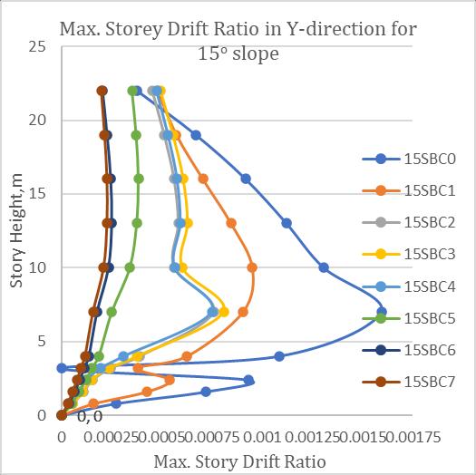
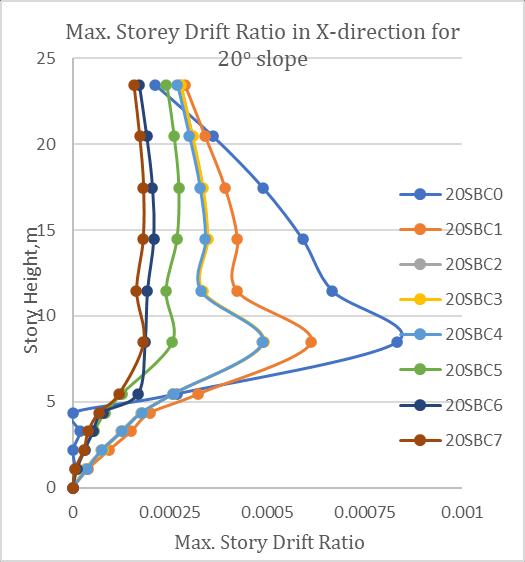
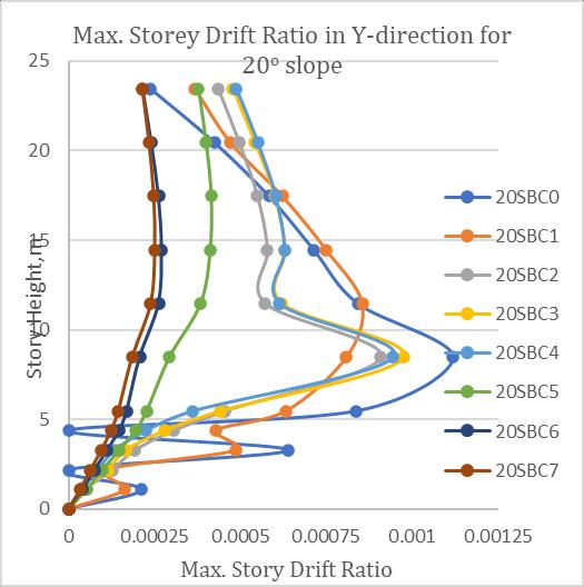
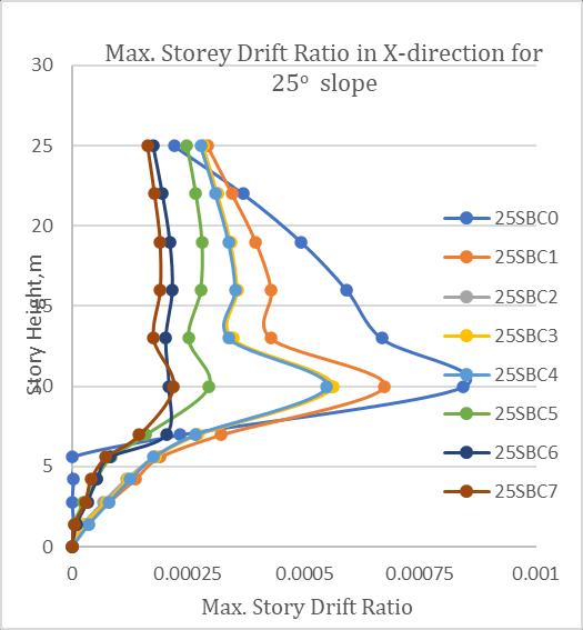
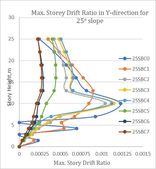
Fig. 11:BaseShearReactionfor20:Slopes Fig. 12:BaseShearReactionfor25:Slopes Storey Drift Ratio StoreyDriftreducesfromSBC0toSBC7 Storey drift along X direction is less when comparedtoStoreydriftalongY direction.
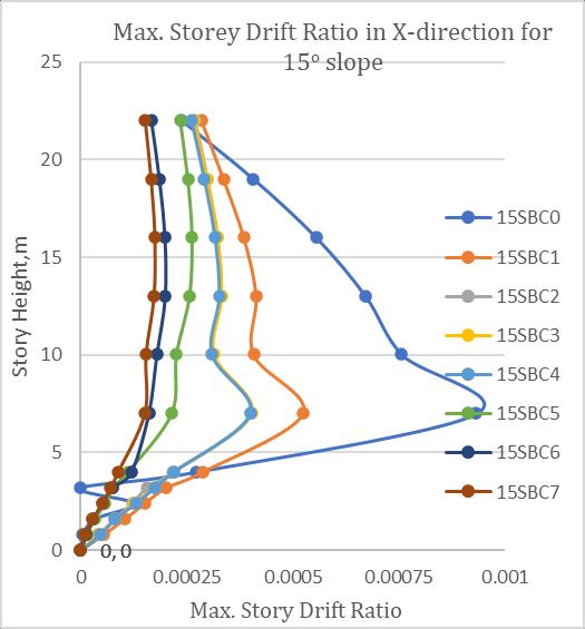
Itisseenthatbelow1ststorylevel,thevariationin storey drift ratio is very irregular. This is been reduced considerably by introducing the Shear walls.
Storey drift ratios for SBC2, SBC3, and SBC4 have similarvaluesasseeninthegraphsabove.
Storey Drift Ratio for the first floor is very much higher compared to all other floors, this is due to theshortcolumneffectbelowthefirstfloor.
For cases SBC5 to SBC7, the storey drift ratio considerably decreases and highly irregular variationinstoreydriftreduceswhichcanseenin fromFig13to18.Thismaybeduetopresenceof ShearwallsonbothX&Ydirections.
Fortypicalcaseofgroundwith20oslope,themax. storeydriftratioat1stfloorlevelforSBC1toSBC4 comparedtoSBC0are73.49%,58.67%,59.15%& 41.2%forXdirectionand72.32%,81.25%,87.5%& 83.93%forYdirectionrespectively(Fig 15&16).
IncasesSBC5toSBC7,thebaseshearalongboththe direction remainssameasthestructureisalmost similarinplanalongbothX&Ydirection,i.e.,Shear wallsaredistributeduniformlyonallside.
Certified Journal | Page612
Volume: 09 Issue: 02 | Feb 2022 www.irjet.net p ISSN: 2395 0072 2022, IRJET Impact Factor value: 7.529 | ISO 9001:2008
Withincreaseinslope(from15o to25o),thebase shear of the structure increases for all cases i.e., SBC0 to SBC7. This is because as the slope of the increases the dead load of building will also increases.
Fig. 10:BaseShearReactionfor15:Slopes
WiththeintroductionofShearwall,thestoreydrift ratiodrasticallyreducesparticularlyinthebottom storiesalongbothX&Ydirection.
However,alongY direction,thestoreydriftratiois veryhighandvariationishighlyirregularcompare to that of along X direction from SBC0 to SBC4 (irrespectiveofinclinationofslopeoftheground) thismaybeduetotheabsenceofShearwallalongY directioninthosecases.
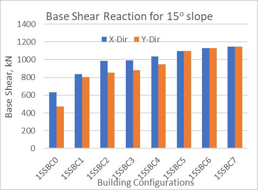
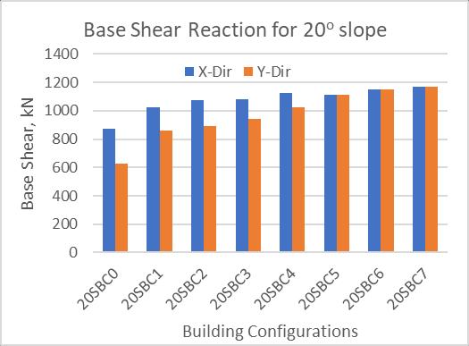
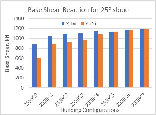
Fig. 15:Max.StoreyDriftRatioinX directionfor20:
International Research Journal of Engineering and Technology (IRJET) e ISSN: 2395 0056 Volume: 09 Issue: 02 | Feb 2022 www.irjet.net p ISSN: 2395 0072 © 2022, IRJET | Impact Factor value: 7.529 | ISO 9001:2008 Certified Journal | Page613
Fig. 14:Max.StoreyDriftRatioinY directionfor15:
Fig. 16:Max.StoreyDriftRatioinY directionfor20:
Fig. 13:Max.StoreyDriftRatioinX directionfor15:
Fig. 17:Max.StoreyDriftRatioinX directionfor25:
Fig. 18:Max.StoreyDriftRatioinY directionfor25:
AstheSlopeofthegroundincrease,theBaseShear ofthebuildingisalsoincreasing.
Certified Journal | Page614
By increasing the Shear walls, the base shear increases and maximum storey displacement and storeydriftratioreduces.
©
Whenmaximumstoreydisplacementisevaluated for different shear wall locations under the same sloping terrain, we come to know that SBC7 has very little displacement compared to the other 7 cases. ForSBC2,SBC3,andSBC4inall3slopinggrounds the displacement values & Storey drift ratios are almostnearerwithfewervariations.
ThepositionofShearwallsplaysaveryimportant roleinthereductionofdisplacementstoreydrifts etc., By introducing the Shear walls the irregularity in thestoreydriftratiocanbereduced.
DisplacementalongY directionismorecompared toX direction WithintroductionofShearwallstheperformanceof thebuildingsuchasmaximumstoreydisplacement, storeydriftcanbeenhanceddrastically.
[4] Mohd. Arif Lahori, Sagar Jamle (2019), "Response of Multistory Building Located on 200 and 300 Sloping GroundunderSeismicLoading",InternationalResearch Journal of Engineering and Technology, (ISSN: 2395 0072(P),2395 0056(O)),vol.6,no.1,pp.1063 1069
International Research Journal of Engineering and Technology (IRJET) e ISSN: 2395 0056 Volume: 09 Issue: 02 | Feb 2022 www.irjet.net p ISSN: 2395 0072 2022, IRJET | Impact Factor value: 7.529 | ISO 9001:2008
ItisalsoseenthatBaseshearincreasesfromcase0 tocase7,i.e.,SBC0toSBC7 Fromthis,wecanconcludethatcase6orcase7i.e., SBC6 or SBC7 is best suited for buildings constructiononhillyterrain.
[1] B.Rohini,et.al.“Analysisof2dFrame(G+10)Buildingon SlopingGround”JournalofEmergingTechnologiesand InnovativeResearch(JETIR),Feb2018,ISSN 2349 5162 [2] B.G. Birajdar, S.S. Nalawade, "Seismic Analysis of Buildings Resting on Sloping Ground", 13th World ConferenceonEarthquakeEngineering,Vancouver,B.C., Canada,August1 6,2004,PaperNo.1472 [3] I.S. 1893 (Part 1) 2016, “Criteria for earthquake resistantdesignofthestructure,generalprovisionand building",BureauofIndianStandards,NewDelhi.
REFERENCES
5. CONCLUSIONS
BaseShearforbuildingwithoutaShearwallisless comparedtothatofbaseshearwitha Shearwall, thisisduetotheintroductionofShearwalls.
