International Research Journal of Engineering and Technology (IRJET) e-ISSN: 2395-0056

Volume: 09 Issue: 12 | Dec 2022 www.irjet.net p-ISSN: 2395-0072
International Research Journal of Engineering and Technology (IRJET) e-ISSN: 2395-0056
Volume: 09 Issue: 12 | Dec 2022 www.irjet.net p-ISSN: 2395-0072
Institute of Science and Technology-Zawiya-Libya ***
Abstract - Since the three-dimensional(3D)Computational fluid dynamic (CFD) flow field investigationtechniques, aswell as advanced flow measurement tools, give potential topredict effects related to blade skew to consider them in blade design.
Through the use of CFD tools and the analysis ofexperimental data that has been published in the literature, the effects of skew applied to the rotor of axial flow turbo engines were examined in this work. Low-aspect-ratio rotors with forward and backward skew have been investigated, and their performance has been compared to that of un-skew datum rotors at various flow rates, span wise positions, and overall efficiency. In this work, the blade sections are swept forward and backward with 3.5 degree and 2.082 degree for dihedral as comparison with data in research and development (R&D) in the field of axial flow turbo machinery (such as fan, compressor, pump) at nowadays. It is focuses on isolated rotors of fluid transporting machines to improve the rotor performance characteristics via thebeneficial modificationon blade aerodynamics, by means of appropriate modification of blade geometry. Nowadays, the enhanced computational resources allow the designer to realize blade design concepts being more sophisticated and complicated than the “classic” designs, e.g. incorporating blade sweep with aid of Computational Fluid Dynamics (CFD) simulations. Threedimensional (3D) CFD flow field investigation techniques, as well as advanced flow measurement tools, give potential to predict effects related to blade sweep and skew to consider them in blade design. It was noted that FSK provides a greater efficiency up to 75% of the blade span at the design point, demonstrating the advantages ofFSKrotorsoverotherrotors.
Near the tip and at smaller radii, the forward-skewed blade increased and decreased inlet axial velocities, respectively.. Due to the small skew angles, the three rotors nearly have similar outlet axial velocities performance. The axial velocity also increases along the dominant part of the span.
At the design flow rate, the forwardskewconsiderablyreduces the radically outward flow along the span andmostlynear the tip.
Key Words: axial flow rotors, backward skew, forward skew,controlledvortexdesign
Axial flow fans are frequently used in engineering and industrial settings. Many researches were carried out for improving the efficiencies by modifying certain geometric features, such as imparting blade sweep and/or skew for development of aerodynamic optimum shape of turbo machinery balding. Computational fluid dynamic (CFD) and numerical simulation have been widely applied in optimization design of fan blades. Up-to-date CFD techniques are available for the reliable predictionof3D turbo machinery flow. Since measurements are expensive, time-consuming and strongly limited from the viewpoint of airfoil variations under investigation, it is beneficial to use CFD tool, which simulates the flow past the cascade of airfoils in a realistic manner. By doing so, it is possible to assess the effects of airfoil shape adjustments on the flow field quickly and more effectively determine the best practices for aerodynamic optimization. It appears to be beneficial to supplement these techniques with analytical models for exploring the underlying physics of 3D flow effects. By using computational fluid dynamic (CFD) techniques and processing experimental data that has been published in the literature, the study aims to evaluate the impact of skew applied to the rotor of axialflowturboengines. At various span-wise positions, low-aspect-ratio rotors with forward and backward skew have been explored and contrasted with unskew datum rotors.. Comparative studies have been carried out on these three rotors at the design flow rates by means of developing structured fully hexahedral mesh of the entire computational domain. The efficiency as well as the losses will be detected on all type of rotors along the span. In order to obtain information on the inter blade flow details, a CFD technique has been developed, using the finite-volume code FLUENT [1]. Using some data obtained for circumferential forward-skewed (FSK) of work of [2], the CFD tool was enabling us to use fixed blade chord along the span for BSK, FSK and USK rotors.
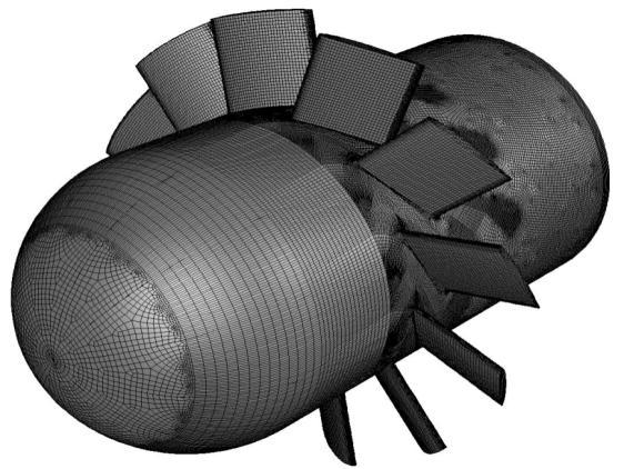
TheflowfieldsinBSK,FSKandUSKrotorsweresimulated bymeansofthesameCFDcodes.Thecomputationdomain for BSK, FSK and USK rotors has been regarded one blade pitchonly.TypicalcomputationaldomainsforUSKrotorare presentedinFigure1.
International Research Journal of Engineering and Technology (IRJET) e-ISSN: 2395-0056
Volume: 09 Issue: 12 | Dec 2022 www.irjet.net p-ISSN: 2395-0072
From above, by evaluating the results of figure (3.a) the
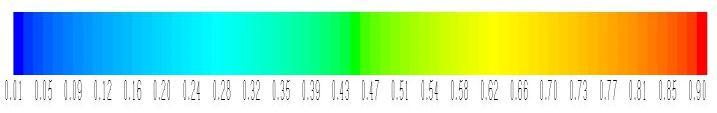
Theinletfaceisasectorofthecircularductwith30 deg central angle. Downstream of the inlet face, sectors of the steadyinletconeandtherotatinghubwithonebladeinthe middleofthedomainareincludedforbothtypesofblading. At the inlet face, a swirl-free uniform axial inlet condition correspondingtotheactualflowratehasbeenprescribed. Thecasingdiameterwasusedasthehydraulicdiameterto calculate the turbulence length scale, with the inlet turbulenceintensityset to 1 percent. The rotor's meshing features are shown in Figure 2. At the outlet boundary (outflowconditioninFLUENT),allflowvariableshavebeen subjectedtoazerodiffusionfluxcondition[1].
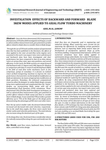
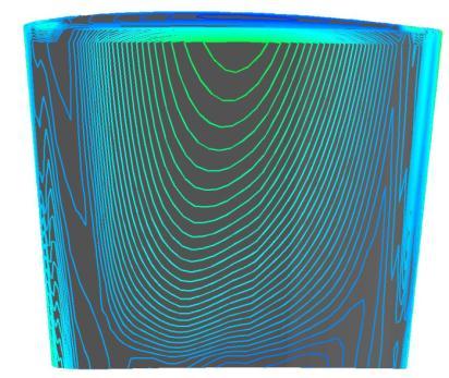
valueoftheskewnessisabout0.29whichisgoodaccording totable1.
(a)
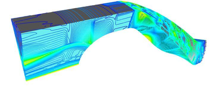
The equiangular skewness of a cell is defined as the maximum value of the ratio of actual and possibly highest deviationfromtheoptimumangle,consideringeachvertex [1]. Decreasing of equiangular skewness was achieved in structured grid. The grid design ensures that 99 % of the cells have equiangular skewness less than 0.6, and the maximumskewnessvalueis0.71.Asthefiguresuggests,the highestskewnessvaluesappearneartheLEandTE.Overthe dominant part of the SS and PS, the skewness is less than 0.35. Figure3(b)showstheskewnessvaluesof thenearblade cells for USK along the axial chord, with zero axial positionattheLEatmidspan.
(b)Blade
(c)Domain
Fig-3:Distributionofcellequiangularskew
FLUENTpackageincludesthefollowingproducts:
•GAMBIT(re-processor):forgeometrymodelingandmesh generation.
•FLUENT (post-processor)[1].
International Research Journal of Engineering and Technology (IRJET) e-ISSN: 2395-0056
Volume: 09 Issue: 12 | Dec 2022 www.irjet.net p-ISSN: 2395-0072
1-Theinletboundaryconditionissetasavelocityinletwhere thevelocityvalueis9.2 [m/s]designflowrate.Theflow directionisparalleltotherotationalaxis,whichmeansthe directionofx.
2-Theblade,hubandoutercasehavebeendefinedaswall, whichdoesnotletthroughtheflowandcreatetheboundary layersaroundthem.
3-Outflowisusedfortheconditionofoutletboundary.
4-theremainingpartofthedomainissetasdefaultinterior andthefluidboundaryconditionisappliedforthisdomain wheretheairdensityisconstantwiththevalueofρair=1.225 [kg/m3]
5-Allthesidesurfacesofthedomainaredefinedasrotational periodic.
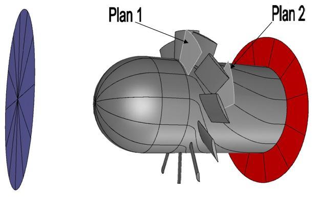
The axial fan is used as the research target, and the computationalfluiddynamicsmethodisusedtosimulatethe three-dimensionalflowoftheaxialfan.First,themodelingof anaxialfanisintroduced.Theinlet(1)andoutlet(2)planes havetheaxialpositionof-20.0and113.0percentmid-span axial chord, respectively, where the zero axial position indicatestheLEatmid-spanasshowninFigure4.
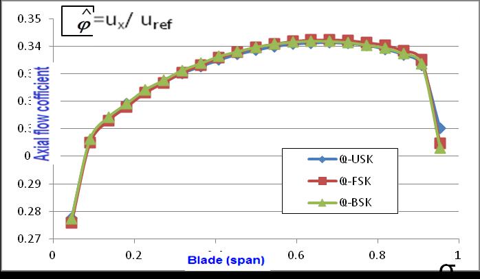
Comparewithothercontributions,theinletflowfieldhasbeeninvestigatedforUSK,FSKandBSK.Thenear-tippartof the forward-skewed blade protrudes into the upstream relativeflowfield,andcarriesoutworkinadvancecompared tothebladesectionsatlowerradii.Thisissuggestedalsoby the generally increased axial velocity near the FSK LE as explainedbyFigure5.Thisresultsinlocallyincreasedinlet axial velocity near the tip, results in the reduction of inlet axial velocity at lower radii of FSK. The same result was suggested by [3]. The inlet axial velocity profile has been foundpracticallyidenticalforthethreerotorsasshownin Figure6. Itseenthatthenear-tippartoftheforward-skewed blade carries out work in advance compared to the blade sectionsatlowerradii.Thisincreasesinletaxialvelocitynear thetip.Increaseofinletaxialvelocitynearthetipresultsin thereductionofinletaxialvelocityatlowerradiiofFSK.The applied blade FSK has an influence on the rotor inlet flow field:theinletaxialvelocityforFSKisincreased at themid span especiallyat70%spanandisreducedatlowerradii,as was observed for FSK rotors also in [4] this effect can be confirmedasasortofsweepratherthandihedral.
TABEL
Therelationshipbetweentheskewandun-skewparameters bladesandthetotalpressureandtheefficiencyoftheaxial fanwereinvestigated.Afterthat,thequalitativecomparison betweenBSK,FSKandUSKrotorsatthedesignflowrateis developedtosolvethecomplexmultiobjectiveoptimization problemwherethetotal pressureandtheefficiencyofthe axial fan are the optimization objectives. Finally, some conclusionsarepresented.Thecharacteristicsandefficiency curves,thecomputationalmeshandboundaryconditionsof theaxialfanarepresentedinthefollowingsections.
sigma INLET FLOW 0 Ҩ-FSK Ҩ-USK Ҩ-BSK 0.045455 0.275799 0.277612 0.277357 0.090909 0.30489 0.305663 0.306251 0.136364 0.31301 0.313279 0.314285 0.181818 0.318034 0.319277 0.319216 0.227273 0.323167 0.323294 0.324224 0.272727 0.326746 0.326904 0.327675 0.318182 0.330493 0.330157 0.33125 0.363636 0.333153 0.332637 0.333757 0.409091 0.335903 0.335024 0.336306 0.454545 0.337813 0.337055 0.338049 0.5 0.339675 0.338569 0.339713 0.545455 0.340866 0.339883 0.340745 0.590909 0.341847 0.340742 0.34153 0.636364 0.342315 0.341202 0.341837 0.681818 0.34241 0.341318 0.34176 0.727273 0.342166 0.341022 0.341382 0.772727 0.341395 0.34035 0.340458 0.818182 0.340445 0.338942 0.339394 0.863636 0.33844 0.336886 0.337261 0.909091 0.335014 0.333075 0.333736 0.954545 0.304674 0.310086 0.303106
International Research Journal of Engineering and Technology (IRJET) e-ISSN: 2395-0056
Volume: 09 Issue: 12 | Dec 2022 www.irjet.net p-ISSN: 2395-0072
Fig-5: Spanwisedistributionsofpitch-averagedofinlet axialvelocitycoefficientatthedesignflowrate.
Figures7and8indicatethat,thethreerotorshavingnearly similaraxialvelocitiesperformance,thisismaybepossibly duetothesmallskewangle.Duetothereducedsizeofthe stagnatingzonenearthetip,thenear-casinglayerofreduced totalpressureriseandaxialvelocityisslightlythinnerinthe caseofskew[5].Theaxialvelocityalsoincreasesalongthe dominantpartofthespanasindicatedbyFigure6.that,the aerodynamicoptimizationdesignofforward-skewedbladeof low-pressureaxial flowfanindicate that the impeller with forward-skewed blades would cause a span wise redistribution of flow rate and pressure toward the blade mid-span, as well as reduce tip loading as shown by [6]. Furthermore,thelocusofmaximumaxialvelocityisshifted towardhigherradii.Thisresultsinincreasedpitchwisearea averagedaxialvelocitynearthetipofFSKandBSKasshown inFigures5.
Fig-6: Distributionsofpitch-averagedofinletaxial velocitycoefficient.
TABEL - 3:Outletflowreadings sigma Outlet Flow 0 Ҩ-FSK Ҩ-USK Ҩ-BSK 0.045455 0.23263 0.229338 0.235929 0.090909 0.272287 0.268923 0.273362 0.136364 0.289379 0.287064 0.290108 0.181818 0.299636 0.297879 0.299996 0.227273 0.310745 0.309278 0.31071 0.272727 0.320734 0.319477 0.320022 0.318182 0.3318 0.330611 0.33058 0.363636 0.341857 0.340806 0.339882 0.409091 0.35278 0.351673 0.350194 0.454545 0.362799 0.361666 0.359263 0.5 0.373713 0.372348 0.369325 0.545455 0.383766 0.382318 0.378232 0.590909 0.395135 0.393409 0.388456 0.636364 0.405894 0.403947 0.397793 0.681818 0.418851 0.415954 0.409248 0.727273 0.431101 0.426558 0.419892 0.772727 0.444234 0.437112 0.431608 0.818182 0.441205 0.437099 0.431412 0.863636 0.353942 0.368714 0.362796 0.909091 0.189944 0.204703 0.21357 0.954545 -0.00571 -0.00077 0.02304
International Research Journal of Engineering
Technology (IRJET) e-ISSN: 2395-0056
Volume: 09 Issue: 12 | Dec 2022 www.irjet.net p-ISSN: 2395-0072
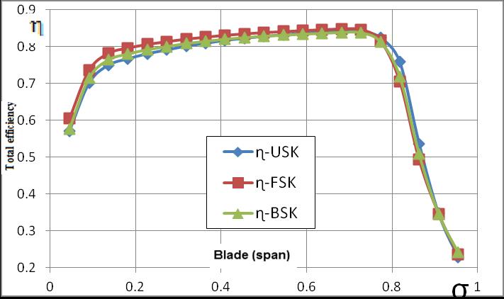
The distributions of the local and pitch-averaged total efficienciesarepresented.Figures 9and10indicatethatFSK andBSK rotorsoperateathigherefficiencythanUSK.The Localtotalefficiencyhasbeendefinedastheratiobetween thelocaltotalpressureriseandtheideallocaltotalpressure rise. The latter was computed using the Euler equation of turbomachinesasaproductofdensity,bladecircumferential velocityatthegivenradius,andlocalabsolutetangentialfluid velocityattheoutlet.ThehigherefficiencyofFSKoccursup to75%bladespanwhichdemonstratesthebenefitsofFSK rotor. In the near-casing zone all rotors demonstrate the sameresults
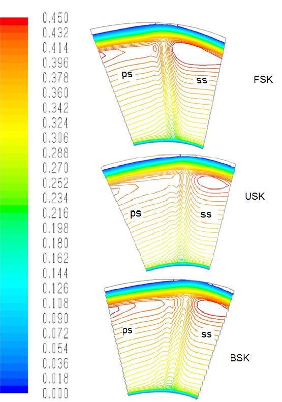
Fig- 7:Spanwisedistributionsofpitch-averagedofthe outletaxialvelocitycoefficientatthedesignflowrate.
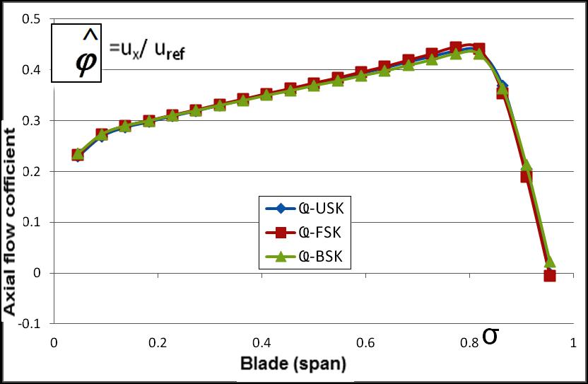
Fig- 8:distributionsofthelocalaxialvelocitycoefficient attheoutletplan
TABEL – 4:
efficiencyreadings sigma Total efficiency 0 ɳ-FSK ɳ-USK ɳ-BSK 0.045455 0.60532 0.571362 0.577276 0.090909 0.735076 0.700468 0.714509 0.136364 0.781872 0.749622 0.764419 0.181818 0.796102 0.76681 0.780265 0.227273 0.806211 0.780468 0.792037 0.272727 0.813517 0.790853 0.800353 0.318182 0.82058 0.801125 0.808655 0.363636 0.82591 0.809075 0.814663 0.409091 0.831033 0.8167 0.820517 0.454545 0.834805 0.822322 0.824622 0.5 0.838337 0.827755 0.828579 0.545455 0.840955 0.831849 0.831273 0.590909 0.843652 0.836266 0.834129 0.636364 0.845955 0.839624 0.836411 0.681818 0.848055 0.842088 0.838781 0.727273 0.846295 0.840412 0.837992 0.772727 0.816425 0.82442 0.813843 0.818182 0.70612 0.758822 0.719623 0.863636 0.492751 0.53674 0.508108 0.909091 0.346111 0.347732 0.346223 0.954545 0.235359 0.228518 0.241963
International Research Journal of Engineering and Technology (IRJET) e-ISSN: 2395-0056
Volume: 09 Issue: 12 | Dec 2022 www.irjet.net p-ISSN: 2395-0072
1.Thecircumferentiallyforward-skewedbladetipcarriesout work on the incoming fluidin advance compared with the bladesectionsatlowerradii.Thisresultsinincreasedand decreasedinletaxialvelocitiesnearthetipandatlowerradii, respectively.
2- The three rotors having nearly similar outlet axial velocities performance, this is may be possibly due to the smallskewangles.Theaxialvelocityalsoincreasesalongthe dominantpartofthespan.
Fig- 9:spanwisedistributionof localtotalefficiencyat designflowrate
3-Atthedesignflowrate,inthenear-casingzoneallrotors demonstrate the about the same results of efficiency. The higherefficiencyofFSKoccursupto75%bladespanwhich demonstratesthebenefitsofFSKrotor.
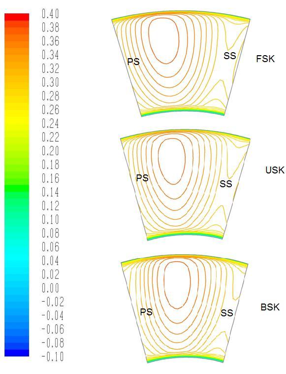
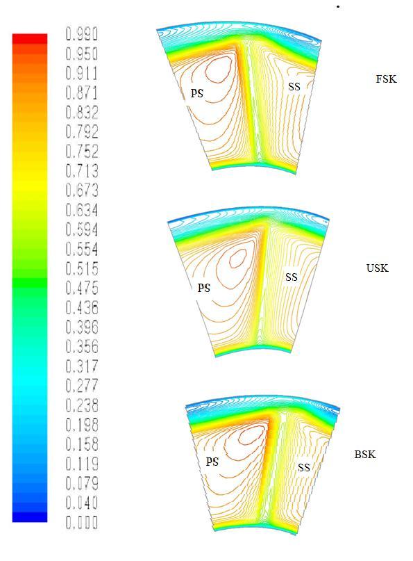
4- Due to forward skew, the isobars are inclined “more forward”forFSKthanforUSKandBSK.Themechanismby whichforwardskewattenuatestheSSradialoutwardflow
[1] FLUENT (FLUENT 6.3.26, 2006) , Fluent Inc., Lebanon, NH,USA.
[2] Vad , J., Kwedikha, A. R. A., Kristóf, G., Lohász, M. M., Rábai, G.,Rácz,N. andWatanabe,K.,2005,“Effectsof blade skew in an axial flow rotor of controlled vortex design.” 6th European Conference on Turbomachinery FluidDynamicsandThermodynamics,LilleProceedings pp.46-55.
[3] JVad ∗,ARAKwedikha, Cs Horváth, M Balczó, M M Lohász,andT Réger (2009). Aerodynamic effects of forward blade skew in axial flow rotors of controlled vortexdesign-Proc.IMechEVol.221PartA:J.Power andEnergyAliR.A.Kwedikha,Aerodynamiceffectsof bladesweepandskewappliedtorotorsofaxial flow turbomachinery-Budapest.
[4] Meixner,H.U.(1995),VergleichendeLDA-Messungenan ungesichelten und gesichelten Axialventilatoren. DissertationUniversitätKarlsruhe,VDI-Verlag, Reih7: Strömungstechnik,No.266,Düsseldorf.
Fig- 10:Spanwisedistributionsoflocaltotalefficiency atthedesignflowrate.
An axial fan rotor of Controlled Vortex Design, having forward and backward skew has been subjected to CFD investigation.Ithasbeencomparedtoanun-skeweddatum rotoratitsdesignflowrate.TheCFDstudiesweresupported by global performance measurements of literatures. The resultsillustratedandsummarizedasfollows:
[5] Vad, J., Kwedikha, A. R. A., Horva´th, Cs., Balczo´, M., Loha´sz, M. M., and Re´gert, T.(2007). “Aerodynamic effects of forward blade skew in axial flow rotors of controlledvortexdesign”.Proc.IMechE,PartA:J.Power andEnergy,2007,221,1011-1023
[6] Li Yang, OuyangHua, and Du Zhao-Hu . ( 2007). Optimization Design and Experimental Study of LowPressure Axial Fan with Forward-Skewed Blades –HindawiPublishingCorporationInternationalJournalof Rotating MachineryVolume 2007, Article ID 85275,10pages-doi:10.1155/85275.
Factor value: