e-ISSN:2395-0056
Volume: 09 Issue: 12 | Dec 2022 www.irjet.net p-ISSN:2395-0072

e-ISSN:2395-0056
Volume: 09 Issue: 12 | Dec 2022 www.irjet.net p-ISSN:2395-0072
1Faculty of Technology and Education, Helwan University, Egypt, 2Faculty of Technology and Education, Helwan University, Egypt, 3 Engineering Department, Faculty of Engineering, Menoufia University, Egypt,
4Faculty of Technology and Education, Helwan University, Egypt, 5Faculty of Technology and Education, Helwan University, Egypt. ***
Abstract – Photovoltaic (PV) grid-connected systems are now a regular component of the contemporary electricity grid. Using transformerless inverters is a new development in these systems' architecture. Despite being small, inexpensive, and efficient, transformerless inverters suffer from chronic leakage currents. Diverse studies have focused on enhancing their performance and decreasing leakage current. This study presents the implementation of a model predictive control (MPC) algorithm to regulate and improve the performance of a grid-connected neutral-point-clamped (NPC) 3- transformerless inverter driven by a photovoltaic (PV) panel. An inductor/capacitor (LC) filter connected the transformerless inverter to the grid. In the system model, both the filter components and the internal impedance of the grid were considered. The discrete model of the proposed system was identified, and the MPC controller's algorithm was constructed. The suggested system was simulated in Matlab using the MPC and the conventional proportional–integral (PI) current controller with sinusoidal pulse width modulation (SPWM). The simulation results indicated that the MPC controller provided the best earth leakage current, total harmonic distortion (THD), and grid current spectrum performance. Additionally, the MPC increased the system's efficiency in comparison to a PI current controller with SPW modulation. simulationresults
Keywords: PV; 3-φ transformerless inverter; NPC; boost converter; model predictive control; maximum power point tracking.
Due to rising awareness of global warming and the anticipated depletion of fossil fuels, the use of renewable energyisrapidlygrowing.Numerous countriesacross the globe promote and stimulate individuals to adopt renewable energy by implementing incentive regulations. Asaconsequence,photovoltaic(PV)systemsthataregridconnectedareincreasinglyprevalentincommunities.
The majority of PV system installs are single-phase installations for small-scale systems ranging from 5 to 6 kW [1]. This style of installation, however, has a smooth directcurrent(DC)inputandapulsingalternatingcurrent (AC) output with a big DC capacitor, which reduces the system's dependability and lifespan. In contrast, the massive capacitor is not needed in three-phase systems, which enhances the system's dependability and lifespan due to its consistent AC output [2]. The inverter is the most important component of the PV system since it serves as the link between the PV system and the utility grid. Typically, the inverter includes a transformer for isolating the PV panel system from the grid and matching the voltage of the system to that of the grid [2]. In other words,thetransformerhelpstoincreasethevoltageofthe PV system when necessary and lowers the injection of harmonics into the grid, hence enhancing power quality [3]. There are two possible designs for integrating the transformer into grid-connected PV systems. In the first arrangement, a high-frequency transformer connects the powerinvertertothePVpanel,whileinthesecond,alowfrequencytransformerconnectsthepowerinvertertothe grid.Thesetransformersaddweight,bulk,andexpenseto the system. Additionally, they degrade efficiency and add complexity to the system. Recently, astonishing new topologies, known as transformerless PV systems, were presented [2,3]. Although these topologies mitigate the disadvantagesoftransformer-basedsystems,theyposean issue with earth leakage current. The lack of galvanic separation between the PV system and the grid is the cause of this issue. Therefore, any potential variations between the PV panels and the ground increase the earth leakage current. This is undesirable because it causes losses, compromises system safety, and distorts grid current. According to research, changes in the commonmode voltage (CMV) of the inverter are the source of the leakage current [4]. In order to reduce leakage current difficulties in transformerless PV systems, it is necessary tomaintainaconstantCMV.
International Research Journal of Engineering and Technology (IRJET) e-ISSN:2395-0056
Volume: 09 Issue: 12 | Dec 2022 www.irjet.net p-ISSN:2395-0072
Several research have suggested transformerless singlephase topologies to address the issue of leakage current [5,6,7,8]. In contrast, three-phase transformerless topology research remains restricted. In the literature, therearetwo methodsforaddressingtheleakagecurrent issueintransformerlessthree-phasesystems:theinverter modulation technique and the inverter structure or topology. Recently, a number of modulation approaches and conversion structures have been revealed. Conventional pulse width modulation (PWM), whether discontinuous PWM (DPWM) or space vector PWM (SVPWM), is insufficient for transformerless three-phase PVapplications due toitshighleakagecurrent.To reduce leakagecurrent,theauthorsofReference[2]introduceda remote-state PWM (RSPWM) approach for a standard three-phase transformerless PV system. The primary drawback of the described modulation approach wasthat it could only be used to two-level inverters with a 650 V DC connection for a 110 V grid phase. The authors of Reference [3] presented the H8 architecture with a modulation mechanism depending on typical sinusoidal PWM (SPWM). However, the large number of power switches increased system losses and decreased its effectiveness. A Z-source inverter (ZSI) architecture was createdinReference[9]byaddingafastrecoverydiodeto decrease leakage current using a modified modulation approach. While overall efficiency was improved, the system and controller were complicated. In addition, a novel three-phase transformerless inverter architecture known as H7 [10,11] has been developed to reduce leakagecurrentwithmodifiedSVPWM.Thissystemyields favorable results based on the leakage current; nevertheless, its efficiency is significantly diminished. Using a novel architecture and modulation approach knownasazero-voltagestaterectifier(ZVR),asdescribed in Reference [12], the reduced leakage current was also accomplished. However, the voltages of the capacitors wereseverelyunbalancedinthisarchitecture.
Among the topologies of 3- transformerless inverters, multilevel inverters, particularly neutral-point-clamped (NPC) inverters, are the most recently used [13,14]. This category is often used in industrial applications. Despite the huge number of switching devices and diodes, NPC is distinguished bya lowtotal harmonicdistortion(THD) of output voltage and a low switching device rating in comparison to two-level inverters. In Reference [15], the authors described two PWM techniques for reducing the common-mode current (CMC) in a three-level NPC inverter. These strategies enhanced CMV, but increased voltage ripples and total harmonic distortion. A multivariable linear quadratic regulator (LQR) for the complete control of a three-level inverter linked to the
gridwithaninductor/capacitor(LC)filterwasreportedin Reference[16].
Numerous academics have recently been interested in modelpredictivecontrol(MPC)approachesforcontrolling power converters [17,18,19,20,21,22,23,24,25,26]. Due to its discrete character, MPC is seen as a beneficial and suitablewayforcontrollingpowerconverters.Inaddition, MPC has several benefits, including simple concept understanding, rapid dynamic reaction, and a straightforwardcontrol method.Inaddition,itcanhandle instances with several variables, impose treatment constraints, and compensate for dead time. Nonetheless, implementation of the MPC method requires several computationsthatarenowsolvedasaresultofsignificant advancements in digital signal processors (DSPs). The MPC approach is used to regulate 3- inverters without transformers. The finite control set MPC approach was usedinReference[27]to eliminatetheleakagecurrentof a T-type transformerless three-level inverter. In addition, a novel MPCcontrol strategyfor thecurrent regulation of a three-phase NPC inverter was developed in Reference [28]. However, the inverter output filter has not been implemented in the system model. Transformerless invertersoftenutilizetunedLCfilterstodecreasethegrid currentharmonicstheyintroduce[29].
This work presents an MPC method for controlling and enhancing the performance of a grid-connected, transformerless NPC 3- inverter driven by a PV panel. Using an LC filter, the transformerless inverter was connectedtothegrid.Theobjectivesofthisstudywereto:
Apply the MPC controller to the suggested system while takingtheLCfilterandgridimpedanceintoaccount.
Discuss the impact of the MPC on performance metrics suchasearthleakagecurrent,gridcurrenttotalharmonic distortion,andefficiency.
Compare the system's performance with the MPC controllertothesystemwiththePIcontroller.
SystemmodelingwastheinitialstageincreatingtheMPC controller. In the system model, both the filter components and the internal impedance of the grid were considered. The discrete-time model was then developed, and the MPC method for the proposed system was described. Finally, the Matlab platform was used to simulate the proposed system and compare the performance of the MPC controller to that of a conventional PI with SPWM. The simulation results demonstrated that the MPC controller provided the optimum earth leakage current, THD, and grid current
International Research Journal of Engineering and Technology (IRJET)
e-ISSN:2395-0056
Volume: 09 Issue: 12 | Dec 2022 www.irjet.net p-ISSN:2395-0072
spectrum performance. In addition, the MPC system was more efficient than the PI current controller with SPW modulation.
The document is formatted as follows: The proposed system is described in Section 2, while its modeling is presented in Section 3. The fourth section discusses MPC controller design and system controllers. Section 5 provides a comprehensive analysis of the simulation results, while Section 6 provides the paper's overall conclusions.
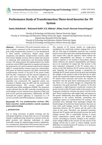
The suggested system is a 3- transformerless inverter powered by PV and connected to the grid. First in the system is the PV panel, which is typically connected to a capacitor at its terminals (see Figure 1). The role of the capacitoristocontrolpowerandenhancePVperformance [30]. The PV output is linked to a boost converter, which functionsasanadjustablePVload.
Predictions of the grid current and filter voltage are essential for MPC controller operation. Modeling the system is the first step in MPC controller design. The following assumptions were used in the mathematical modelofthesystem:
1-Boostconverterlossesareneglected.
2-Voltagedropsandleakagecurrentsofalltheswitching devicesareneglected.
3-Snubbercircuitsareneglected.
4-Thegridinternalimpedanceistakenintoconsideration.
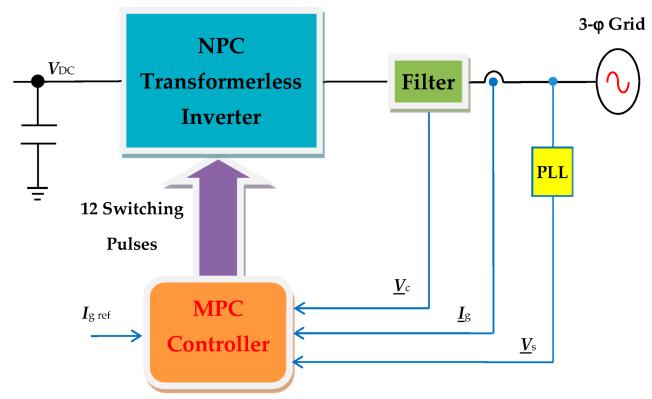
Figure 1. The proposed photovoltaic (PV)-powered 3level transformerless inverter is connected to the grid and its controllers..
By adjusting the boost converter, the maximum power point tracking (MPPT) functioning of the PV may be achieved. In addition, the boost converter may increase the PV voltage at low insolation levels. Therefore, it supports modest PV power extraction levels. The boost converteroutputterminalsindicatetheDClink,connected to the 3- transformerless inverter input. The topology of the transformerless 3- inverter is NPC. At the inverter output terminals that are linked to the utility grid, an LC filter is installed. The filter prevents high-frequency ripples and dampens the dynamics of the current [31]. Each component's design and functioning will be describedinthefollowingparagraphs.
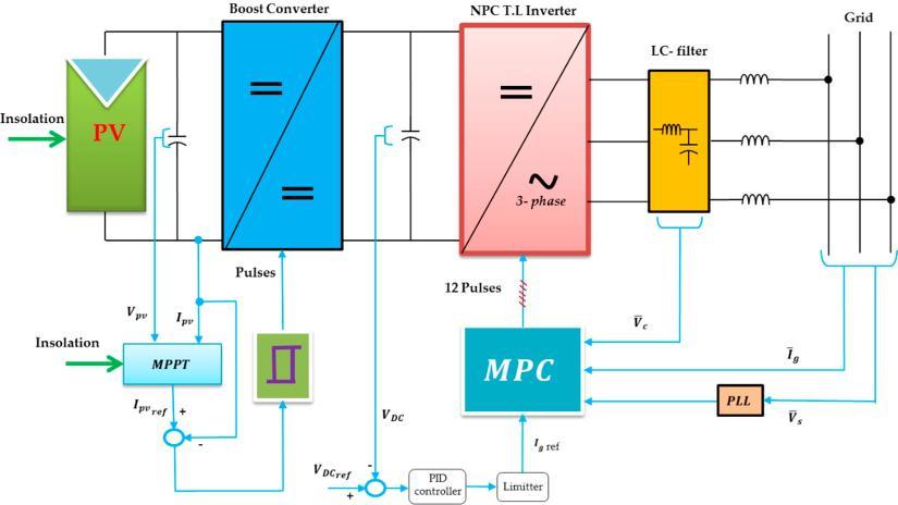
Figure 2. ModelofthePVpanel,where ISC isthepanel shortcircuitcurrentand(Rp, Rs)isthemodelparalleland seriesresistances.
3-2. Boost Converter Dynamic Model
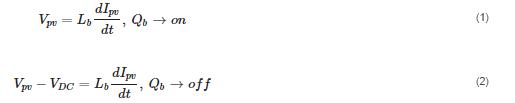
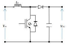
3.2. Boost Converter Dynamic Model Figure 3 shows the power circuit of the boost converter. Its input is the PV panel output and the output feeds the DC link voltage of the 3-level transformerless inverter. Its function was to regulate the PV power to operate at MPPT conditions. Assuming that the DC link capacitor is large enough, the dynamic model of the converter is specified by the followingequations[33]:
whereLbistheboostconverterinputinductanceand (VDC)istheDClinkvoltage
International Research Journal of Engineering and Technology (IRJET) e-ISSN:2395-0056
Volume: 09 Issue: 12 | Dec 2022 www.irjet.net p-ISSN:2395-0072
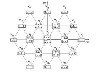
Figure 4a depicts the power stage of the NPC 3-level inverter. It has12 IGBTsandsix clampdiodes. The image shows that the DC bus voltage has to be separated using twocapacitors.Asillustratedin Figure4b,itiscommonly known that the NPC 3-level inverter has 27 states. When represented as space vectors, these states provide 19 voltage vectors (V1,...V19). There are only seven states with zero common-mode voltage, as mentioned in Reference [15]. (V8, V10, V12, V14, V16, V18, V0). To restrict the CMV of the NPC three-level inverter, the preceding seven switching states were used. Therefore, theearthleakagecurrentmaybeeliminated.
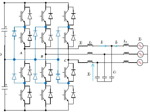
As shown in Figure 4a, the transformerless NPC inverter wasconnectedtothegridthroughanLCfilter.Thesource inductance(lg)wastakenintoconsiderationinthemodel. The grid was assumed to be an infinite 3-φ bus that had constant frequency and voltage amplitude. All 3-φ voltages and currents are expressed as space vectors using:
where(ua,ub,anduc)arethethree-phase quantities,uis the equivalent space vector, and a = e j(2π/3) . From the circuit’s basic laws, the system dynamic behavior can be expressedby:
where (ua, ub, and uc) are the 3-φ quantities, u is the equivalentspacevector,and a = ej(2π/3).
Fromthecircuit’sbasiclaws,thesystemdynamicbehavior canbeexpressedby:

where(Lf, Cf)isthefilterinductanceandcapacitance.The filter capacitor voltage vector is Vc, the inverter voltage vector is Vi, the grid current vector is Ig, and the filter currentvectoris If.
3.3.2.Discrete-TimePredictionofthe3-φ Transformerless InverterModel
International Research Journal of Engineering and Technology (IRJET) e-ISSN:2395-0056
Volume: 09 Issue: 12 | Dec 2022 www.irjet.net p-ISSN:2395-0072
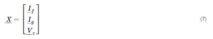
Equations (4)–(6) can be rewritten in the state space systemmatrixform:
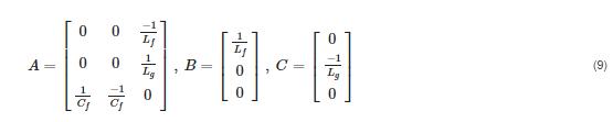
Equations(4)–(6)canberewritteninthestatespace systemmatrixform: (8) where
introduces three controllers to illustrate the control system for the proposed PV grid-connected system. The first controller is the MPPT controller, which changes the PV operating of the transformerless NPC inverter controller.
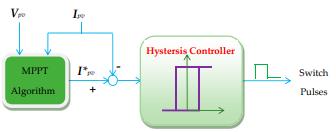
It is crucial to obtain the greatest amount of electricity from PV systems for optimal use. Therefore, functioning undertheMPPTconditionisimportantforthesesystems. Numerous approaches for MPPT have been developed [34,35]. Utilizing the maximum allowable PV power, the incrementalconductanceMPPTtechniquewasusedinthis study. According to [30], the method involves tracing the slope of the PV power and voltage curve (dPpv/dVpv) untilitreacheszero.
ontherightoftheMPPTconditionatthecurve
3.3.2.Discrete-TimePredictionofthe3-ϕTransformerless InverterModel
Implementation of the MPC algorithm requires prediction of the future values of the controlled quantities. The prediction process is accomplished using the system discrete model. Usually, this model is determined by the forwardEulerapproximation: whereTsisthesamplingtime.WiththehelpofEquation (10),thestatespaceequationin(8)couldbetransformed intodiscreteas: (11) where ∫ ∫ (12)
Fromtheseequations,thesystemvariablesforthenext samplecanbepredicted.Anoptimizationprocessisthen adaptedtodirectthesystemtothesetpoint.Thisprocess willoccurusingthecostfunction.
Point as near as possible to MPPT conditions. The MPPT algorithm produces the reference current for a currentregulated boost converter, which maintains MPPT conditions. The second controller is the DC link voltage controller, which maintains a predetermined VDC value. ThethirdcontrollerregulatesthegridcurrentThissection
attheMPPTcondition (13)
>0ontheliftoftheMPPTconditionatthecurve
The incremental conductance approach produces the reference current to a current-regulated boost converter, as shown in Figure 5. The reference current is compared to the PV current generating an error signal that derives thehysteresiscontroller.Inturn,thehysteresiscontroller produces the required duty cycle signals for the boost convertertransistor
ThiscontrollermanagestheDClinkvoltage,whichplaysa crucial role in power transmission and systemstability.It creates the current value of the reference grid. For stabilityreasons,thiscontroller'sreactionmustbeslower than that of the inverter controller. Fortunately, the enormous capacitor value at the DC connection terminals slows down the system's reaction. The PI controller is suitable since the set value is constant. The Nichehols–
International Research Journal of Engineering and Technology (IRJET) e-ISSN:2395-0056
Volume: 09 Issue: 12 | Dec 2022 www.irjet.net p-ISSN:2395-0072
Ziegler approach is used to optimise the PI controller settings.
TheMPCstrategyreliedon anticipatingthefuturealtered variables of the model in order to enhance system performance. MPC methods for power electronic systems are distinct due to the fact that power electronic systems always use power converters. Typically, these converters have a restricted number of possible switching states. In such situations, the approach hinges on choosing the switching state that brings the output of the system as near as feasible to its respective reference throughout each sampling interval. Using the system model, the behaviour of the variables may be predicted for each sample state. Then, an optimization is designed and implementedtoguaranteethattheidealswitchingstateis selected. This optimization is characterised by a cost function that will be evaluated for each promising switching state. The best and most appropriate switching state is then chosen based on the minimization of the derived cost function. Figure 6 depicts the control structure of the proposed system. This controller's objectives were to manage the grid current vector (Ig) to follow its sinusoidal reference and achieve unity power factoroperationforgrid-suppliedelectricity.
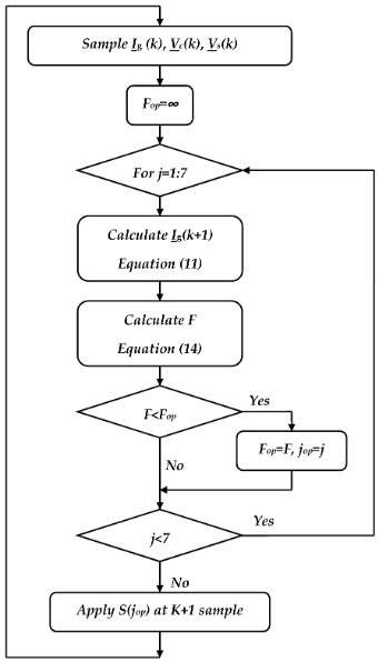
Figure7.MPCalgorithmflowchart.
The cost function is the core of the MPC optimization process.ToachievetheMPCgoals,Fischosentominimize the grid current error. F is defined as the square of grid currenterror,asgivenby:
Figure6.Modelpredictivecontrol(MPC)blockdiagram.
The procedure of prediction relies on the measured variables(Ig(k),Vs(k),andVc(k)).Usingthesystemmodel and data, the prediction of Ig(k + 1) for each effective switching state was then determined. In turn, the prediction evaluated the cost function necessary to achieve the control objectives. The valid switching state, whichgivestheminimalcostfunction,wasthenchosenfor thesubsequentsamplinginterval.AflowchartfortheMPC controller of the NPC transformerless inverter is seen in Figure7.
where(igα,igβ)aretherealandimaginarycomponentsof Ig and (i * gα, i * gβ) are the real and imaginary componentsofthegridcurrentreference.
Figure 1's suggested system is simulated using the Matlab/Simulink platform. Table 1 contains a list of system parameters. Typically, the power ratings of three-
International Research Journal of Engineering and Technology (IRJET)
e-ISSN:2395-0056
Volume: 09 Issue: 12 | Dec 2022 www.irjet.net p-ISSN:2395-0072
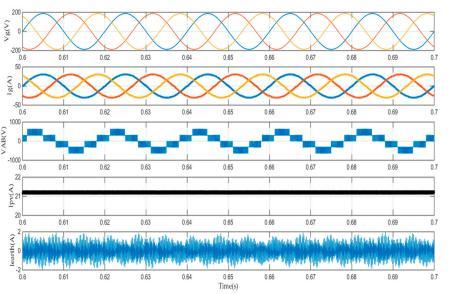
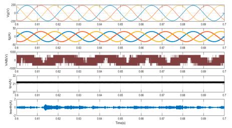
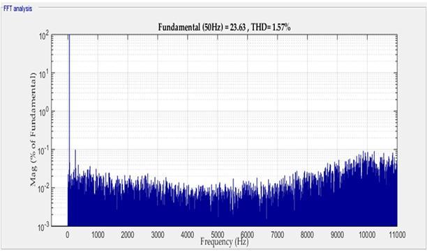
phaserooftopsystemsrangebetween10and15kW.This studyusedapowerratingof10kW.Usingtheassumption that the 3- grid was (380 V, 50 Hz), the usual DC bus voltage for the transformerless inverter was 650 V [1]. In order to attain that value of VDC and output power of 10 kW,theconstructionofthePVpanelwas960seriescells6 parallel strings. Capacitance was used to simulate the leakage capacitance (Cearth) between the cells and the grounded frame. It may have values between 50 and 150 nF [36], depending on air conditions and panel construction.Insimulation,however,thevalueof(Cearth) was set to 100 nF. The sampling time (Ts) was chosen based on the actual amount of time required to complete onecontrolalgorithmrun.Thefollowingparameterswere chosenbecausetheyareroutinelyutilisedfor3-inverters in practise. The results of the proposed transformerless NPCinvertercontrolledbytheMPCcontroller(Figure 8a) and the PI current controller with SPW modulation are comparedinFigure8.Withthetwocontrollers,the3-grid currentsaresinusoidalandinphasewiththegridvoltage (unitypowerfactor).ThegridcurrentTHDis1.22percent with the MPC controller and 2.23 percent with the PI controller.Asthecontrolleractionsvary,thewaveformsof the inverter output line voltages also change. The PV currents for both controllers are identical, since the same MPPTcontrollerisusedinbothinstances.Regardingearth leakage current, it is evident that the MPC controller case isfarsmallerthanthePIcontrollercase.
1.Table System parameters Parameter
Figure8.Simulationresultsoftheproposedneutral-pointclamped (NPC) transformerless inverter in terms of grid voltage, grid current, PV current, and earth leakage current with (a) the MPC controller and (b) the proportional–integral (PI) current controller with sinusoidalpulsewidthmodulation(SPWM).
International Research Journal of Engineering and Technology (IRJET) e-ISSN:2395-0056
Volume: 09 Issue: 12 | Dec 2022 www.irjet.net p-ISSN:2395-0072
r case. In MPC, not all the voltage vectors are used, only those that minimize leakage currents. The PI cFigure 9 showsthevariationoftheRootMeanSquare(RMS)value oftheleakagecurrentwiththeisolationlevel.Theleakage currentwiththeMPCcaseislessthanone-thirdthevalue ofthePIcontrolleontrollerwithSPWmodulationutilizing all the voltage vectors. Hence, the leakage current is smallerintheMPCcase.Furthermore,theleakagecurrent drops for the MPC controller, while remaining nearly constant with the PI controller. This phenomenon is explainedinthefollowingparagraphs.
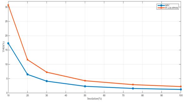
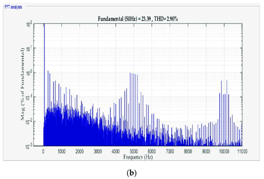
Figure 11 shows the variation of the frequency spectrum of the grid current with the isolation level. The figure showsthelower-orderharmonicsintheMPCcaseareless than the lower order harmonics in the PI controller case. Generally, the value of the harmonics is lowest for MPC cases.Theoptimization mechanismin theMPCminimizes THDinthegridcurrentsincethecostfunctionfocuseson the error present in the grid current. The PI controller with SPW modulation does not possess this optimization. For this reason, the THD is does not possess this optimization.Forthisreason
Figure9.Variationoftheleakagecurrentwiththe insolationlevelfortheMPCcontrollerandPIcurrent controllerwithSPWmodulation
ItiswellknownintheliteraturethatCMVfluctuationsare themaincauseofleakagecurrent.BycheckingtheCMVof the two controllers, it was observed that with PI there were small CMV variations with the insolation variation. TheMPCcasehadmoderateCMVvariations.
Figure10showsthevariationofthegridcurrentTHDwith the isolation level. Comparing the THD for the two cases shows that THD with MPC produces less than 50% of the value than THD with the PI controller. This result can be explained by the current-error-minimization process that occurswhentheMPCcontrollerisused.
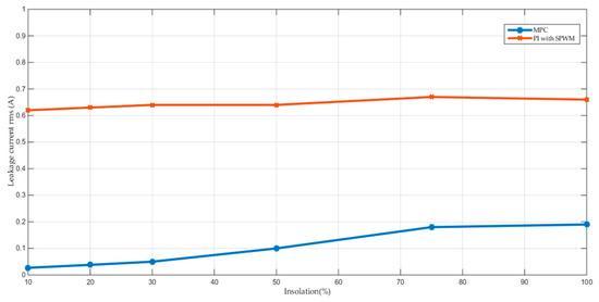
Figure10.Figure10.Variationofthegridcurrenttotal harmonicdistortion(THD)withtheinsolationlevelforthe MPCcontrollerandPIcurrentcontrollerwithSPW modulation.
(a) (b)
(a)MPCcontroller,and(b)PIcurrentcontrollerwithSPW modulation(at75%insolation).Figure11.Thespectrum ofthegridcurrentforthe(a)MPCcontrollerand(b)PI currentcontroller
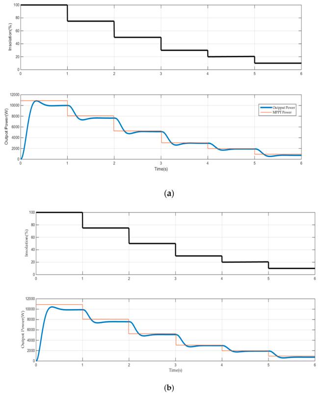
Figure 12 presents the response of the output power and maximum power point (MPP) power in the case of the MPC controller (Figure 12a) and the PI current controller with SPW modulation (Figure 12b). The output power of
International Research Journal of Engineering and Technology (IRJET) e-ISSN:2395-0056
Volume: 09 Issue: 12 | Dec 2022 www.irjet.net p-ISSN:2395-0072
thetwocasestrackstheMPPpowerwithaforcedsteadystate error representing system losses. The losses in the MPC controller cases are smaller than in the PI controller cases. The reason for this difference is because a small THD produces harmonic losses. Losses increase with increasing power levels, which is considered a normal issue since current values increase as power levels increase.
harmonicsaredifferent.Thesedifferencesarebecausethe MPC controller provides better switching patterns and lower harmonics than other controllers. The higher efficiency is thought to come from the small switching losses and low harmonic losses of the MPC controller.
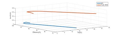
Figure 14 provides a line diagram of the major performance factors, including THD, efficiency, and leakage current. The figure shows great improvement in leakagecurrentreduction.
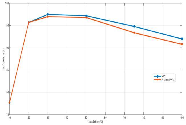
Figure 13. Variation of the system efficiency with the insolation level for the MPC controller and PI current controller with SPW modulation
Figure 12. The maximum power point (MPP) power and output power at step insolation variations for the (a) MPC controller and (b) PI current controller with SPWM.
Figure 13 shows the variation of system efficiency with insolation level for the MPC controller and PI current controller with SPW modulation. Under all insolation levels, the efficiency of the MPC controller is higher than thatofthePIcontroller.Theproposedsystemefficiency(η ηc)hasbeendeterminedforthetwocontrollersusingthe followingequation[37]:
ηC = 0.05η100% + 0.21η75% + 0.53η50% + 0.12η30% + 0.05η20%+0.04η10% (15)
Theefficiencyis95.62%fortheMPCcontrollercaseand 94.99% for the PI current controller case. As the two compared cases use the same hardware but have a different controller, the inverter switching pattern and
Figure 14. Line diagram of the THD, efficiency, and leakage current for the MPC controller and PI current controller with SPW modulation
This paper proposes the use of an MPC controller with a grid-connected NPC transformerless inverter powered by PV.ThroughanLCfilter,thetransformerlessinverterwas coupled to the grid. In the system model, both the filter components and the internal impedance of the grid were considered. The discrete model of the proposed system was identified, and the MPC controller's algorithm was constructed. The suggested system (controlled by MPC) and a system using a conventional PI current controller
International Research Journal of Engineering and Technology (IRJET) e-ISSN:2395-0056
Volume: 09 Issue: 12 | Dec 2022 www.irjet.net p-ISSN:2395-0072
with SPW modulation were simulated in Matlab. The simulationresultsdemonstratedthefollowing:
(1)TheMPCcontrollerhadthebestperformancebasedon allcomparativevariables.
(2) With the two controllers, the 3- grid currents were sinusoidal and in phase with the grid voltage (i.e., unity powerfactor).
(3) The grid current THD was 1.22 percent with the MPC controllerand2.23percentwiththePIcontroller.
(4) The MPC case's leakage current was less than onethirdthatofthePIcontrollercase.
(5)ThesystemusingtheMPCwasmoreefficientthan the system employing the PI current controller with SPW modulation.
CMV Common-modevoltage
CMC Common-modecurrent Cearth
Theleakagecapacitance
DPWM DiscontinuousPWM
DSP Digitalsignalprocessor
F Thecostfunction Ig
Thegridcurrentvector
If Thefiltercurrentvector Iearth
Theearthleakagecurrent
ISC Thepanelshortcircuitcurrent (igα, igβ) The real and imaginary componentsof Ig
(i*gα, i*gβ) The real and imaginary componentsofthegridcurrentreference lg
Thesourceinductance Lb The boost converter input inductance (Lf, Cf) Thefilterinductanceandcapacitance.
MPP Themaximumpowerpoint
MPC Modelpredictivecontrol.
MPPT Maximumpowerpointtracking NPC Neutral-point-clamped.
RSPWM Remote-statePWM (Rp,Rs)
Themodelparallelandseries
[1] 1-ZAID, Sherif A., et al. Performance Improvement of H8 Transformerless Grid-Tied Inverter Using Model Predictive Control Considering a eak rid. Processes, 2022,10.7 1243
[2] 2- F I, elqasem,etal. nalysisofaPhotovoltaic ystem ased on a ighly fficient ingle-Phase TransformerlessInverter. nergies,2022,15.17 6145
[3] 3-JAHAN,Sumaya,etal.H9andH10Transformer-less olar Photovoltaic Inverters for eakage Current uppression and armonic Current eduction. I TransactionsonIndustry pplications,2022
[4] 4-ZAID, Sherif A., et al. Performance Improvement of H8 Transformerless Grid-Tied Inverter Using Model Predictive Control Considering a eak rid. Processes, 2022,10.7 1243.
[5] 5-SAIFIZI, M., et al. Implementation of Two-Stage MultilevelInverterSystemUsingPICController.Journalof Advanced Research in Applied Sciences and Engineering Technology,2022,28.2:41-55.
[6] 6- I, diti tul I I I, uresh , Tomonobu. ovel 6 Transformerless Inverter for rid Connected Photovoltaic ystem to educe the Conduction ossand nhance fficiency. nergies,2022,15.10 3789
[7] 7-Kerekes, T.; Teodorescu, R.; Liserre, M.; Klumpner, C.; Sumner, M. Evaluation of three-phase transformerless photovoltaic inverter topologies. IEEE Trans. Power Electron.2009,24,2202–2211.[CrossRef]
[8] 8-Cavalcanti,M.C. e liveira, .C. e I I, asoud, etal. IC asedCascaded -bridgeInverterfor eakage Current uppression inP ystems. I Transactions on Power lectronics,2022
[9] 9-DHANAMJAYULU,C.;SANJEEVIKUMAR,P.;MUYEEN, S. M. A structural overview on transformer and transformer-less multi level inverters for renewable energy applications. Energy Reports, 2022, 8: 1029910333.
[10] -T. Kereke, R. Teodorescu and U. Borup, “TransformerlessPhotovoltaicInverters
[11] Connected to the rid,” P C 07-Twenty-Second Annual IEEE Applied PowerFarias, A.M.; Neves, F.A.; Azevedo, G.M.; Camboim, F.C. Modulation techniques to eliminateleakagec
International Research Journal of Engineering and Technology (IRJET) e-ISSN:2395-0056
Volume: 09 Issue: 12 | Dec 2022 www.irjet.net p-ISSN:2395-0072
[12] ALJAFARI, Belqasem, et al. Analysis of a Photovoltaic System Based on a Highly Efficient Single-Phase TransformerlessInverter.Energies,2022,15.17:6145.
[13] -RAO, Pandry Narendra; SAINI, Lalit Mohan. Photovoltaic‐based grid‐connected transformer‐less three‐phase cascaded diode‐clamped multilevel inverter with reduced leakage current. International ournal of CircuitTheoryand pplications,2022
[14] 12-SHAHAB Electronics Conference and Exposition, pp.1733–1737,2007.
[15] 14- S. Boulahchiche, S. Makhloufi, S. Semaoui, A. H. Arab,A.D.Guerbi,andK.
[16] bdeladim, “ xperimental nalysis of rid Connected to PV System According to DIN VDE 0126-1-1,” no. October,2018.
[17] 15- N. H. Khan, S. Member, M. Forouzesh, S. Member, Y.P.Siwakoti,andS.Member,
[18] “TransformerlessInverterTopologiesforSingle-Phase PhotovoltaicSystems:A
[19] Comparative eview,”I Trans.Ind. lectron,vol.8, no.1,pp.1–39,2020.
[20] urrents in transformerless three-phase photovoltaic systems. IEEE Trans. Ind. Electron. 2009, 57, 1360–1368. [CrossRef]
[21] 16- Gupta, A.K.; Agrawal, H.; Agarwal, V. A Novel Three-PhaseTransformerlessH-8TopologyWithReduced LeakageCurrentforGrid-TiedSolarPVApplications.IEEE Trans.Ind.Appl.2018,55,1765–1774.[CrossRef]
[22] -Cavalcanti, M.C.; Farias, A.M.; Oliveira, K.C.; Neves, F.A.; Afonso, J.L. Eliminating leakage currents in neutral point clamped inverters for photovoltaic systems. IEEE Trans.Ind.Electron.2011,59,435–443.[CrossRef
[23] -González, R.; Lopez, J.; Sanchis, P.; Marroyo, L. Transformerless inverter for single-phase photovoltaic systems. IEEE Trans. Power Electron. 2007, 22, 693–697. [CrossRef]
[24] -Xiao, H.; Xie, S.; Chen, Y.; Huang, R. An optimized transformerless photovoltaic grid-connected inverter. IEEE Trans. Ind. Electron. 2010, 58, 1887–1895. [CrossRef]
[25] -Kerekes, T.; Teodorescu, R.; Rodríguez, P.; Vázquez, G.; Aldabas, E. A new high-efficiency single-phase transformerless PV inverter topology. IEEE Trans. Ind. Electron.2009,58,184–191.[CrossRef]
[26] - Freddy, T.K.S.; Rahim, N.A.; Hew, W.P.; Che, H.S. Comparison and analysis of single-phase transformerless grid-connected PV inverters. IEEE Trans. Power Electron. 2013,29,5358–5369.[CrossRef]
[27] - Bradaschia, F.; Cavalcanti, M.C.; Ferraz, P.E.; Neves, F.A.; dos Santos, E.C.; da Silva, J.H. Modulation for threephasetransformerlessZ-sourceinvertertoreduceleakage currents in photovoltaic systems. IEEE Trans. Ind. Electron.2011,58,5385–5395.[CrossRe
[28] - Guo, X. Three-phase CH7 inverter with a new space vector modulation to reduce leakage current for transformerless photovoltaic systems. IEEE J. Emerg. Sel. Top.PowerElectron.2017,5,708–712.[CrossRef]
[29] - Freddy, T.K.S.; Rahim, N.A.; Hew, W.P.; Che, H.S. Modulationtechniquestoreduceleakagecurrentinthreephase transformerless H7 photovoltaic inverters. IEEE Trans.Ind.Electron.2014,62,322–331.[CrossRef]
[30] 25-Guo, X.; Zhang, X.; Guan, H.; Kerekes, T.; Blaabjerg, F. Three-phase ZVR topology and modulation strategy for transformerless PV system. IEEE Trans. Power Electron. 2018,34,1017–1021.[CrossRef]
[31] - Krishna, R.A.; Suresh, L.P. A brief review on multilevel inverter topologies. In Proceedings of the InternationalConferenceonCircuit,PowerandComputing Technologies (ICCPCT), Nagercoil, India, 18–19 March 2016;pp.1–6.[CrossRef]
[32] -Akbari, A.; Poloei, F.; Bakhshai, A. A Brief Review on State-of-the-art Grid-connected Inverters for Photovoltaic Applications. In Proceedings of the IEEE 28th International Symposium on Industrial Electronics (ISIE), Vancouver,BC,Canada,12–14June2019;pp. 1023–1028. [CrossRef]
[33] -Zhang, H.; Jouanne, A.V.; Dai, S.; Wallace, A.K.; Wang, F. Multilevel inverter modulation schemes to eliminate common-mode voltages. IEEE Trans. Ind. Appl. 2000, 36, 1645–1653.[CrossRef]
[34] -Alepuz, S.; Busquets-Monge, S.; Bordonau, J.; Gago, J.; Gonzalez, D.; Balcells, J. Interfacing Renewable Energy Sources to the Utility Grid Using a Three-Level Inverter. IEEE Trans. Ind. Electron. 2006, 53, 1504–1511. [CrossRef]
International Research Journal of Engineering and Technology (IRJET) e-ISSN:2395-0056 Volume: 09 Issue: 12 | Dec 2022 www.irjet.net p-ISSN:2395-0072
[35] -Correa, P.; Rodriguez, J.; Rivera, M.; Espinoza, J.R.; Kolar, J.W. Predictive Control of an Indirect Matrix Converter. IEEE Trans. Ind. Electron. 2009, 56, 1847–1853.[CrossRef]
[36] -Mohamed,I.S.;Zaid,S.A.;Elsayed,H.M.;Abu-Elyazeed, M.F.Implementationofmodelpredictivecontrolforthreephase inverter with output LC filter on eZdsp F28335 Kit using HIL simulation. Int. J. Model. Identif. Control 2016, 25,301–312.[CrossRef]
[37] -Gulbudak,O.;Santi,E.Apredictivecontrolschemefor a dual output indirectmatrixconverter.InProceedings of the IEEE Applied Power Electronics Conference and Exposition(APEC),Charlotte,NC,USA,15–19March2015; pp.2828–2834.[CrossRef]
[38] -Vazquez, S.; Leon, J.; Franquelo, L.; Rodriguez, J.; Young, H.A.; Marquez, A.; Zanchetta, P. Model Predictive Control:AReviewofItsApplicationsinPowerElectronics. IEEEInd.Electron.Mag.2014,8,16–31.[CrossRef]
[39] -Corts, P.; Kazmierkowski, M.P.; Kennel, R.M.; Quevedo, D.E.; Rodrguez, J. Predictive control in power electronicsanddrives.IEEETrans.Ind.Electron.2008,55, 4312–4324.[CrossRef]
[40] -Corts, P.; Ortiz, G.; Yuz, J.I.; Rodrguez, J.; Vazquez, S.; Franquelo, L.G. Model predictive control of an inverter withoutputLCfilterforUPSapplications.IEEETrans.Ind. Electron.2009,56,1875–1883.[CrossRef]
[41] -Mohamed,I.S.;Zaid,S.A.;Elsayed,H.M.;Abu-Elyazeed, M.F. Improved model predictive control for three-phase inverter with output LC filter. Int. J. Model. Identify. Control2015,23,371–379.[CrossRef]
[42] -Wang, J. Model Predictive of Power Electronic Converter. aster’s Thesis, orwegian niversity of ScienceandTechnology,Norway,Trondheim,2012.
[43] -Vaccari,M.; Pannocchia, G. A Modifier-Adaptation Strategy towards Offset-Free Economic MPC. Processes 2017,5,2.[CrossRef]
[44] -Li, W.; Kong, D.; Xu, Q.; Wang, X.; Zhao, X.; Li, Y.; Han, H.; Wang, W.; Chen, Z. A Wind Farm Active Power Dispatch Strategy Considering the Wind Turbine PowerTracking Characteristic via Model Predictive Control. Processes2019,7,530.[CrossRef]
[45] - Xiaodong, W.; Zou, J.; Ma, L.; Zhao, J.; Xie, C.; Li, K.; Meng, L.;Guerrero, J.M.Model predictivecontrol methods of leakage current elimination for a three-level T-type
transformerlessPVinverter.IETPowerElectron.2018,11, 1492–1498.[CrossRef]