1.2 OBJECTIVES OF PNEUMATICS
2.
International Research Journal of Engineering and Technology (IRJET) e ISSN: 2395 0056 Volume: 09 Issue: 01 | Jan 2022 www.irjet.net p ISSN: 2395 0072 © 2022, IRJET | Impact Factor value: 7.529 | ISO 9001:2008 Certified Journal | Page1086 PNEUMATIC AUTO FEED DRILLING MACHINE Shashi Prakash1 , Ealmer2 , Vishwa3, Suryya4, Rajesh5 1 4Diploma in Mechanical Engineering Student, P.S.G. Polytechnic College, Coimbatore 5Professor, P.S.G. Polytechnic College, Coimbatore *** Abstract In small scale industries and automobile maintenanceretailers,therearefrequentwantsofdrilling, boring, and grinding. Vast and sophisticated designed elements cannot be machined with the assistance of a standard machine and any for each operation separate machine is needed so increasing the amount of machines needed and increasing the world needed for them to be accommodated and thence overall initial price needed. In our project the higher than difficult issues are reduced.
1.1 PRINCIPLE OF PNEUMATICS
Huge and sophisticated designed elements cannot be machined with the assistance of a standard machine and any for each operation separate machine is needed thus increasingtheamountofmachinesneededandincreasing the world needed for them to be accommodated and thence overall initial value needed. In our project the on topofsophisticatedissuesaredecreased.Bytheappliance ofmechanics,thegascylinderwithpistonthatisoperated by associate degree compressor can provide the serial action to work this machine. By this we will succeed our industrialneeds.
Themainobjectiveofourprojectistoperformvaried machining operations victimization "Auto feed mechanism" indrillingmachinewiththeassistanceof gas sources. For a developing trade the operation performed and therefore the elements (or) elements made ought to have it minimum doable cost for it to run profitableness. In small scale industries and automobile maintenance outlets, there are frequent wants of modification and loosening of screws, drilling, boring, grinding, reaming, taperecordingandbroachingmachine.
Tosucceedproduction Tocutbackmanpower Toincreasethepotencyoftheplant Tocutbacktheworkload Tocutbacktheassemblyvalueandtime Tocutbackthefabrichandling Tocutbackfatigueofstaff Maintenance LITERATURE REVIEW
The most objective of our project is to perform varied machining operations victimization “Auto feed mechanism” in drilling machine with the assistance of pneumatic sources.During a singlemachineall thehigher than specified operation are often administered, i.e., once drilling, the drill head is aloof from the barrel key and therefore the needed tools like grinding wheels, boring tooletc.,are often connected,and therefore theoperation are often performed. By the applying of pneumatics, the pneumatic cylinder with piston that is operated by air compressor can provide the serial action to work this machine.Bythiswewillattainourindustrialnecessities.
2.1 AUTO INDEXING GEAR CUTTING ATTACHMENT FOR SHAPING MACHINE Srujan Manohar, S.Hari Krishna, University Collegeofengineering,JNTU,A.P,INDIA{2012): Theyhavebeeninvestigatedtousepneumatic shaper for high production of automatic gear cutting with auto indexing work piece. A small ratchet gear structure has been thus devised to demonstrate the gear cutting attachment in shaping machines. The
Key Words: Auto feed mechanism, Pneumatic sources, Drillhead,Barrelkey,Pneumaticcylinder,Aircompressor
The word mechanics is that the study of air movement. The laws of physics dictate that uncontained gases can fill any given house. The best thanks to see this in action is to inflate a balloon. The elastic skin of the balloon holds the air tightly within, however the instant you utilize a pin to make a hole within the balloon's surface, the air expands outward with most energy that theballoonexplodes.Compressionagasintoalittlehouse may be a thanks to store energy. Once the gas expands once more, that energy is discharged to try to do work. Thatistheprinciplebehindmechanics.
Automation will be achieved through computers, hydraulics, pneumatics, robotics, etc., of those sources, mechanicstypeaprettymediumforlowpriceautomation. Themostadvantageofagassystemisthatit'seconomical and easy in construction that makes it totally different from alternative sources of automation. Automation plays a crucial role in production. These days the majority the producingmethodisdynamictomachine drivenmachines soastodeliverthemerchandisewithhigherqualityandat aquickerrate.Theproducingoperationisbeingmachine drivenforthesubsequentreasons.
Less
M.V.N
1. INTRODUCTION

2.2 DESIGN & FABRICATION OF PNEUMATICALLY OPERATED PLASTIC INJECTION MOULDING MACHINE
The key a part of any gas machine is provide of compressed gas is by suggests that reciprocal mechanical device.Amechanicaldevicecouldbeamachinethattakes in air, gas at a definite pressure and delivers the air at a high. Designed for either stationary (or) transportable service the reciprocal mechanical device is out and away theforemostcommonsort.
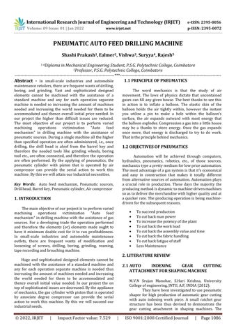
3.1 DOUBLE ACTING CYLINDER
pneumaticsourceofpowerwithcontrolaccessoriesis usedto drive the ram orthecylinder pistonto obtain theforwardandreturnstrokes. By this arrangement the forward/reverse stroke of the pneumatic cylinder is adjustable type when compared with the conventional machines. We desired a shaping machine which will automatically index the job and gives automatic tool feed to the pneumaticcylinder
Adoubleactingcylinderisutilizedontopofthings systemswiththetotalpneumaticartifactandit'sessential once the cylinder itself is needed to retard serious hundreds. This will solely be done at the top positions of thepistonstock.Alltoldintermediatepositionsaseparate outwardly mounted artifact device should be given the dampingThefeature.normal escape of air is out off by a padding pistonbeforethetopofthestockisneeded.Asaresultthe sitewithinthepaddingchamberisoncemorecompressed since it cannot escape however slowly per the setting createdonreverses.Theairfreelyentersthecylinderand therefore the piston stokes within the different direction atfullforceandspeed.
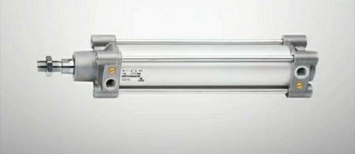
3.2 RECIPROCATING COMPRESSORS
2.3 DESIGN AND DEVELOPMENT OF SEMI AUTOMATIC CUTTING MACHINE FOR YOUNG COCONUTS Satip Rattanapaskorn' Kiattisak Roonprasang' King Mongkut's Institute of Technology Ladkrabang, Bangkok10520,Thailand(2008): The purpose of this analysis is to style, fabricate, test, and valuate the model of a semi automatic young coconut fruit cutting machine. The lookconceptionisthatfruitcuttingisaccomplishedby gas go on a young coconut sitting on a pointy knife during a vertical plane. The machine consists of five mainparts:1)machineframe,2)cuttingbase,3)knife set,4)gassystem,and5)tanksreceivingcoconutjuice andcutfruits. The machine elements contacting edible elements of the fruit square measure made from food grade chromesteel.Operating,ayoungcoconutisplacedon thecuttingbaseandthereforethegasmanagementis switched on. The coconut is mechanically moved to the pressing unit and cut in half by a knife set. The coconut juice flows right down to the tank whereas the cut fruits square measure separated and moved intotheoppositetank
Pneumatic systems operate a provider of compressed gas that should be offered in sufficient amount and at a pressuretosuitthecapabilityofthesystem. When the gas system is being adopted for the primary time, but it'll so be necessary to manage the section of compressedgasprovide.
Fig 1:Doubleactingcylinder
International Research Journal of Engineering and Technology (IRJET) e ISSN: 2395 0056 Volume: 09 Issue: 01 | Jan 2022 www.irjet.net p ISSN: 2395 0072 © 2022, IRJET | Impact Factor value: 7.529 | ISO 9001:2008 Certified Journal | Page1087
Poonam G. Shukla, Gaurav, P. Shukla Nagpur, India {2013): This project intends to use of plastic is inflated currently days in several industries like automobile, packaging, medical, etc. the rationale behind thisis often thatthe plasticcreated things are quieteasiertomanufacture,handleandreliabletouse that the plastic merchandise producing industries are pains arduous to provide smart quality merchandise atgiantscaleandcheaperprice Thehydraulicallyoperatedmachinessolvethe matter,howeverthey'retoocostlierfortinyscaleand medium scale industries. This paper deals with style and fabrication of pneumatically operated injection plastic moulding machine. The operated by hand machine is regenerate into pneumatically operated machinebyapplyingcorrectstyleprocedure.
3. DESCRIPTION OF EQUIPMENTS
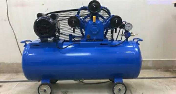
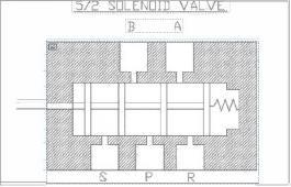
Commonly referred to as DCV, this valve is employed to manage the direction of air flow within the gassystem. Thedirectional valvewill this by dynamic the position of its internal movable elements. A magnet is associate degree device that converts current into line motion and force. The assorted elements of magnet valve andtheiroperatingareaunitmentionedbelow. The magnet valve has five openings. This ensures straightforward exhausting of 5/2 valve. The spool of the 5/2 valve slide within the most bore in line with spool position; the ports get connected and disconnected. The workingruleisasfollows
Reciprocal compressors deliver over five hundred m3/min. In single stage mechanical device, even though the gas pressure is of 6 bar, the machines will discharge pressureoffifteenbars.Dischargepressurewithinvaryof 250 bars is obtained with high reciprocal compressors thatof3&fourstages.
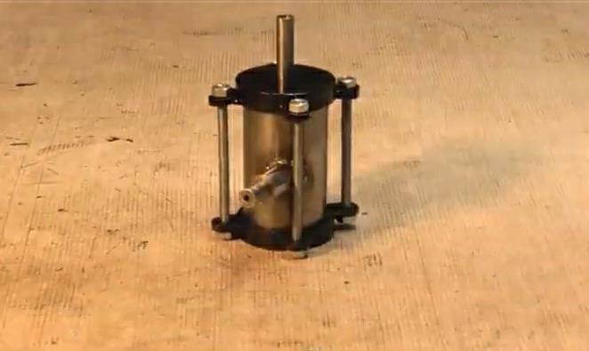
Itisa pneumaticmotorwhichrunsbysupplying by compressed air, for performing any operation the pneumaticmotor,whencompressedairimpingesonrotor ofthemotoritrotatesandthebarrelwhichwasconnected to rotor is rotated, there by various operations are performed by changing various tool bits from the barrel. With its industrial grade 3/8" chuck, this economical choice includes high quality features for general drilling and hole sawing jobs. The planetary gear reduction balancestheloadonbearingsandgearsforincreasedtool life.
Fig ReciprocatingCompressors
2:
3.3 5/2 WAY SOLENOID VALVE
Fig 4:PneumaticMotor
3.5 CONTROL UNIT (SEQUENCE TIMER)
3.4 PNEUMATIC MOTOR
International Research Journal of Engineering and Technology (IRJET) e ISSN: 2395 0056 Volume: 09 Issue: 01 | Jan 2022 www.irjet.net p ISSN: 2395 0072 © 2022, IRJET | Impact Factor value: 7.529 | ISO 9001:2008 Certified Journal | Page1088
Fig 3:5/2waysolenoidvalve
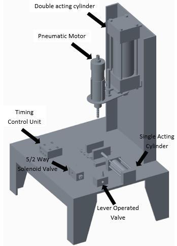
Timing control unit (sequence timer) is connected tosolenoidvalvetocontrolthetimerequiredforchanging the workpiece by supplying electriccurrenttochangethe valve direction. When timing control unit is switched on, electriccurrentissuppliedtosolenoidvalvewhichinturn drilling operation takes place as it supplies air for piston downwardmotionandpneumaticmotor Whenthetimingcontrolunitisswitchedoff,electric current is not supplied to the solenoid valve and drilling operation does not takes place as valve direction is changedandnowairissuppliedforpistonupwardmotion and drill head moves up (i.e. air stops supplying to pneumatic motor and piston downward motion). Also we can set the sequence time for drilling next workpiece automaticallyifwecanchangetheworkpieceinaconstant time.
4. SPECIFICATIONS OF COMPONENTS AND DESIGN CALCULATIONS Table -1: DoubleactingCylinder Strokelength 140mm=14cm Pistondiameter 40mm Pistonrod 10mm Quantity 1 Seals Nitride(Buna N)elastometer Endconespiston CastironEN 8 Media Air Temperature 0 70C
Position 1: once the spool is motivated towards outer direction port 'P' gets connected to 'B' and 'S' remains closedwhereas'A'getsconnectedto'R' Poisition-2: once the spool is pushed within the inner directionport'P'and'A'getsconnectedtoeverydifferent and'B'to'S'whereasport'R'remainsshut
air
xP=(π
International Research Journal of Engineering and Technology (IRJET) e ISSN: 2395 0056 Volume: 09 Issue: 01 | Jan 2022 www.irjet.net p ISSN: 2395 0072 © 2022, IRJET | Impact Factor value: 7.529 | ISO 9001:2008 Certified Journal | Page1089 Table 2: 5/2waysolenoidvalve Size 0.635X10^ 2m Portsize G0.635x10^ 2m Maxpressurerange 0 8bar Table 3: Flowcontrolvalve Portsize 0.635x10^ 2m Pressure 0 10bar Media Air Table 4: Hoseconnectors Maxworkingpressure 10bar Temperature 0 80C Fluidmedia Air Material Brass Diameter 06mm Locking Self locking Table 5: Hoses Maxpressure 8bar Outerdiameter 8mm=8x10^ 3m Innerdiameter 3mm=3x10^3m Material Polyurathene Table -6: BarrelUnit Shortcapacity 0.635X10^ 2m Barrelinnerdiameter(ID) 30mm=30x10^ 3m Drillcapacity 1.5 l0mm Table 7: Foundation Basementdepth 1ft Lengthofbeam 4ft Breadthofbeam 2ft Heightofthebeam 2.5ft Table 8: Designcalculations 4.5 FABRICATION
The stand (or) base carries the total machine. the total machine is put in on the muse .A circular column having length of 90cm concerning one third half of} its length is within the foundation the remains part is on top of the muse, from the higher finish of the vertical column 50cmismachinedbyplayactingturningoperation,abush withhavinglengthseven.5cmismachinedandslidesover themachiningelementsofrod. Thehorizontalrodisslideroverthe,verticalcolumn by means that of bush. A double acting cylinder is connected to horizontal column by mistreatment clamp for feeding of the machine. A gas motor with chuck is connected to the horizontal column commonly. A 5/2 means coil worth is connected to manage the double actingcylindertoupward&downwardmotion. Oneacting cylinder and a movable jaw is fastened to the bottom of themachineit'llactasapiecedevice. 8bar Area of cylinder (A) (π/4)x(D²) Force exerted in thepiston(F) Pressureappliedxareaofcylinder Force extraction (FE) /4)x(D²) /4) Kg retraction (FR) of in in retraction
(π/4)x(D² d²)xP=(π/4)x(5² 1.5²)x8=143N=14.5kg Consumption
extraction (CE) (π/4 ) x (D²) x (P+ 1) x L)/1000 = (π/4)x(5²)x(8+1)x16)/1000= 2.82lt/min Consumption of air
Force
(π
x(5²)x8= 157N=16
(CR) (π/4)x(D² d²)x(P+1)xL)/1000 = (π/4) x (5² 1.5²) x 9 x 16) / 1000=2.57lt/min
cylinder(P)inpressureMaximumappliedthe
The compressed gas from the mechanical device is employedbecausetheforcemediumforthisoperation.Air motor and double acting cylinder is employed during this machine. The air from the mechanical device enters the coil valve. From the coil valve, air enters into the gas motor and double acting cylinder’s piston downward motionport(connectedthroughhoseconnectors)through means a method (a technique a way) and also the different way of air enters to the double acting cylinder’s piston upward motion port. A vice is fastened to the bottomofthemachinewhichcanactasapiecedevice. Once air enters the piston downward motion port because of pressure distinction the drilling head comes downandata similartime airentersthe gasmotor(with chuck containing tool bit) and drills (rotates) the work piece. Flow management valve is provided to each gas motor and double acting cylinder to regulate the speed (motorrpm)andfeed(upanddownmotion)severally.
Temporalordermanagementunit(sequencetimer)is connected to coil valve to regulate the time needed for dynamic the work by provision current to vary the valve direction. once temporal order management unit is switched on, current is provided to coil valve that successively drilling operation takes place because it providesairforpistondownwardmotionandairmotor. Whenthetemporal arrangementmanagementunit is changed, current isn't provided to the coil valve and drilling operation doesn't takes place as valve direction is
6. WORKING
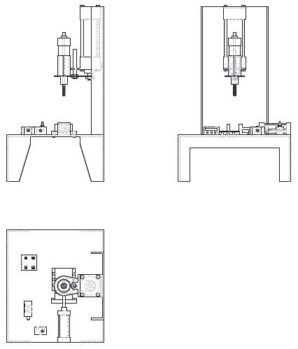
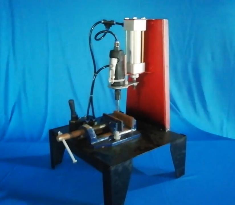
International Research Journal of Engineering and Technology (IRJET) e ISSN: 2395 0056 Volume: 09 Issue: 01 | Jan 2022 www.irjet.net p ISSN: 2395 0072 © 2022, IRJET | Impact Factor value: 7.529 | ISO 9001:2008 Certified Journal | Page1090 Fig 5:Pneumaticautofeeddrillingmachineisometricand orthogonalviewsof3dmodel Fig 6:Pneumaticautofeeddrillingmachine Photographs
REFERENCES
Further study is to be done to enhance the performance parameters like output and potency. The subsequent modifications are to be drained this machine infuture,theyare Tool ever changing additionally to be done mechanically by victimization decide and place automaton By ever changing the work device we will performradialdrillingoperation By constrain the tool bit move we will perform shapingoperation Gear cutting is additionally attainable by ever changingtheworkdevice.
[4]
[1] M.V.N. srujan manohar and S. Hari Krishna “Auto indexing gear cutting attachment for shaping machine”(2012) PoonamG,Shukla,gauravandP.Shukla“Design& fabrication of pneumatically operated plastic injectionmouldingmachine”(2013) Satip Rattanapaskorn' Kiattisak roonprasang “Design and development of semi automatic cuttingmachineforyoungcoconuts”(2008) A.S. Aditya polapragada and K. Sri Varsha “Pneumatic auto feed punching and riveting machine”(2012) R.H.WARRNING“Pneumatichandbook” Festocatalogues
9.1
International Research Journal of Engineering and Technology (IRJET) e ISSN: 2395 0056 Volume: 09 Issue: 01 | Jan 2022 www.irjet.net p ISSN: 2395 0072 © 2022, IRJET | Impact Factor value: 7.529 | ISO 9001:2008 Certified Journal | Page1091 modified and currently air is provided for piston upward motionanddrillheadmovesup(i.e.airstopsprovisionto gasmotorandpistondownwardmotion). Additionallywe will set the sequence time for drilling next work mechanically if we will modification the work in a very constanttime. 7. ADVANTAGES Itreducesmanualworkandquickinoperation. Accuracyismoreandoccupieslessspace. Lowcostmachineandeasymaintenance. Consumption of electric power is less when comparedtomanualmachines. In a single machine many operations are performedlikedrilling,tapping,reaming,grinding byjustchangingthetoolbit. 8. APPLICATIONS Used in automobile workshops for drilling mechanicaldeviceholes. Usedintinyscaleindustries. For playing the operations in large numbers that cannot be tired standard machines, since it's transportable. Inattachmentbuygrinding. In such places wherever frequent amendment operativeisneeded. 9. CONCLUSIONS
The project allotted by us created associate impressing task within the field of tiny scale industries and automobile maintenance outlets. It's terribly usefully for the staff to hold out variety of operations in an exceedingly single machine. Automation is attainable for big scale industries however not for little scale industries therefore we have a tendency to adopt low price automation and medium of effort is additionally is freely ontheThismarket.project has additionally reduced the price concerned within the concern. Project has been designed to perform the whole demand task that has additionally been provided. This project work has provided us a wonderful chance and skill, to use our restricted information. We have a tendency to gained heaps of sensible information relating to, planning, purchasing, collectingandmachiningwhereasdoingthisprojectwork. Wehaveatendencytofeelthattheprojectworkcouldbe a sensible resolution to bridge the gates between the establishmentandthereforetheindustries We square measure proud that we've completed the work with the limited time with success. PNEUMATIC AUTOFEED DRILLING MACHINE is functioning with satisfactory conditions. Ready to} able to perceive the difficulties in maintaining the tolerances and conjointly thestandard.We’vedonetoourabilityandabilitycreating mostuseofaccessiblefacilities. FUTURE SCOPE
[3]
[5]
[6]
[2]