International Research Journal of Engineering and Technology (IRJET) e-ISSN:2395-0056

Volume:09Issue:11 | Nov 2022 www.irjet.net p-ISSN:2395-0072

International Research Journal of Engineering and Technology (IRJET) e-ISSN:2395-0056
Volume:09Issue:11 | Nov 2022 www.irjet.net p-ISSN:2395-0072
Merin Roy1 , Dr. Jisha Kuruvilla2
1PG Scholar, Department of EEE, MACE, Kothamangalam, kerala, India
2Professor, Department of EEE, MACE, Kothamangalam, kerala, India ***
Abstract - At the present time, the vector control
technique is widespread used in high performance induction motor drive. The performance of hysteresis controller and SVPWM method in a vector controlled drive is designed. The THD analysis of vector controlled drive is also analysed. With hysteresis current controller, the Fast Fourier transformer profile of the output voltage generated by the VSI is similar to that of a space vector modulated VSI, by maintaining nearly constant switching frequency. Variations in machine parameters can contribute to change in desired switching frequency. The proposed controller assures that the VSI is switched in a pattern similar to SVM. Space vector based and hysteresis current controlled VSI fed IM drive is simulated using MATLAB R2017a.
Key Words: Spacevector,Switchingfrequency,MATLAB, dSPACE
Inductionmotoriswidelyusedintheindustriesduetoits exclusive features such as high robustness, high reliability and efficiency as well as low cost and maintenance.Thisresultstoitsincreaseddemandinhigh performance applications. Using the through vector control method, the induction motor is able to be controlled like a DC motor. The 3-phase stators and 3phase rotors are considered as two fundamental parts of a 3-phase AC induction motor. When the 3-phase stators are energized by the 3-phase AC power source, current flow is generated in the stators. The magnetic field synthesized by 3-phase stator current is always rotating incessantly with the variation of the current. This rotating magnetic field cuts the rotor and the current generated in it interacts with the rotating magnetic field and thus produces the magnetic torque which makes the rotor rotate. The rotating speed of the rotor n should be less than that of the rotating magnetic field.Reverserotatingoftherotorwillberealizedbytwo ofthe3-phasepowersourcepositionsexchanged.
The rotating direction of the rotating magnetic field is consistent with the current phase and its speed is proportional to the power source frequency f and inversely proportional to the magnetic polar pair number.
SVPWM is a modulation algorithm which translates phase voltage (phase to neutral) references, coming from the controller, into modulation times/duty-cycles to be applied to the PWM peripheral. It is a general technique for any three-phase load, although it has been developed for motor control. For induction machines, the most common choices for the direct axis is to align it to the rotor field (rotor FOC) or to the stator field (stator FOC). SVPWM just does a lot of sampling,calculatingandwaveformmanipulation.SVmeans space vector, as in space vector modulation. SVM basically allows a 3-phase bridge PWM drive to supply about 15 percent higher peak voltage to a motor than the standard sine-triangle modulation scheme by allowing the neutral pointofthemotortomoveawayfromthenominal1/2ofthe supply rail. The Space Vector Pulse Width Modulation (SVPWM)referstoaspecialswitchingsequenceoftheupper three power devices of a three-phase voltage source inverters (VSI) used in application such as AC induction and permanent magnet synchronous motor drives. It is a more sophisticated technique for generating sine wave that provides a higher voltage to the motor with lower total harmonicdistortion.SpaceVectorPWM(SVPWM)methodis an advanced; computation intensive PWM method and possibly the best techniques for variable frequency drive application. SVPWM generates less harmonic distortion in the output voltages and currents in the windings of the motor load and provides a more efficient use of the DC supply voltage in comparison with sinusoidal modulation techniques. Since SVPWM provides a constant switching frequency; the switching frequency can be adjusted easily. The basic principle of SVPWM is based on the eight switch combinations of three phase inverter. The switch combinations can be represented as binary codes that correspond to the top switches S1, S3 and S5 of the inverter. Each switching circuit generates three independent pole voltagesVao,Vbo andVco.
International Research Journal of Engineering and Technology (IRJET)
e-ISSN:2395-0056
Volume:09Issue:11 | Nov 2022 www.irjet.net p-ISSN:2395-0072
pulse-widthmodulation[1]. Space vector based hysteresis controller for VSI fed IM drive is introduced. Hysteresis current controller has a simple implementation, fast transient response and direct limitation of the peak current. Hysteresis current controlisrelativelyasimplemethodforPWMtechnique withcomparativelygoodcurrentloopresponse. ��
Figure1–Hysteresiscurrentcontrol
a combination of the two adjacent active switching vectorsandoneorbothofthezerovectors
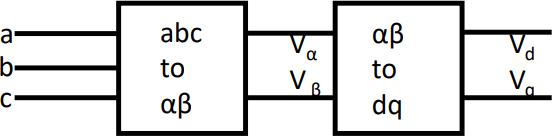
Clark transformation or αβγ transformation is a mathematical transformation employed to simplify the analysis of three-phase circuits. One very useful application of the αβ transformation is the generation of the reference signal used for space vector modulation controlofthree-phaseinverters.
RotatingSpaceVector,U(t) isrepresentedas U(t)=(Ua+Ube^(j(2/3)∗pi)+Uce^((j(−2/3)∗pi)2/3)
ThevoltagevectorV1isgivenbythe 1 = 2��dc 3
Thegeneralequationforvoltagevector, switchingsignals.Theactualphasecurrentiscompared to sinusoidal wave references current which are producedbythecontrolcircuit.Theupperswitch(S1)is
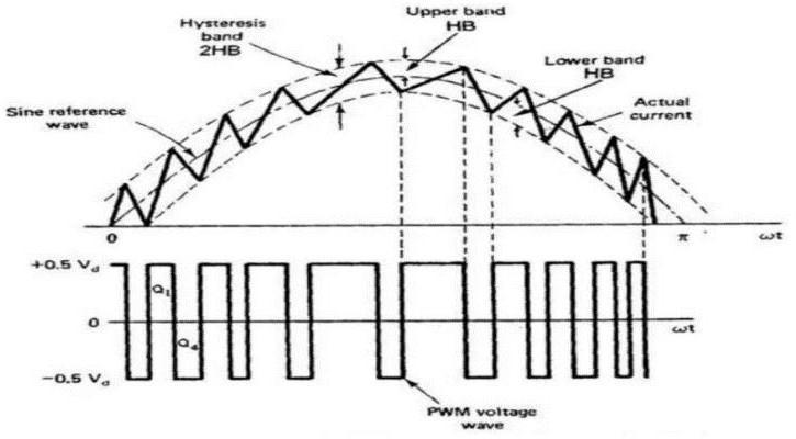
As shown in Figure 1, current control under hysteresis band principle operation in generating the PWM
2 ����= 3������ ∗ �� j(n−1)∗pi/3 turned off and the lower switch (S4) is turned on when the actual current exceeds the higher band limit. As a results, the output voltage changes from +0.5Vdc to0.5Vdc The actual current start to decrease and drop until it crosses the lower band limit. At this time, the lower switch is turned off and the upper switch is turned on. Then, the output voltage changes from -0.5 Vdc to +0.5 Vdc and the current starts to increase. This processisthencontinuouslyrepeated.
A space vector is a sinusoidal voltage vector with constant amplitude and rotating at constant frequency. It is used for the creation of alternating current (AC) waveforms; most commonly to drive 3 phase AC poweredmotorsatvaryingspeedsfromDC.
Three-phase VSI generates eight switching states which includesixactive and two zero states. These vectors form a hexagon which consisting of six sectors spanning 60 each. The reference vector which represents three-phase sinusoidalvoltageisgeneratedusingSVPWMbyswitching betweentwonearestactivevectorsandzerovector.
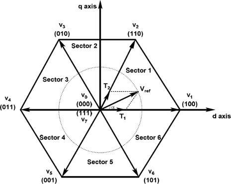
To implement space vector modulation, a reference signal Vref issampled witha frequency fs (Ts = 1/fs). The reference signal may be generated from three separate phase references using the αβ transform as shown in Figure2.Thereferencevectoristhensynthesizedusing
To calculate the time of application of different vectors, consider Figure3, depicting the position of differently availablespacevectorsandthereferencevectorinthefirst sector.Table1showstheswitchingstatescorrepondingto
International Research Journal of Engineering and Technology (IRJET)
spacevector Thesinusoidal referencespacevectorform a circular trajectory inside the hexagon The largest output voltage magnitude that can be achieved using SVPWM is the radius of the largest circle that can be inscribed within the hexagon This circle is tangential to the mid points of the lines joining the ends of the active spacevector.
Figure 4 shows the leg voltages and space vector dispositionforoneswitchingperiodinsectorI.

SVPWM based controller
MATLAB is a high-performance language for technical computing. It integrates computation, visualization, and programming in an easy way to use environment where problems and solutions are expressed in familiar mathematical notation. SIMULINK is a software package for modelling, simulating, and analysing dynamical systems.
Simulationparametersfor1HPInductionMotorisgivenin Table3.SimulinkmodelforvectorcontrolledIMdriveand hysteresiscontrollerisdesigned.Simulationiscarriedout using1HPinductionmotorwithfollowingparameters.
Table2–Switchingtimeinallsectors
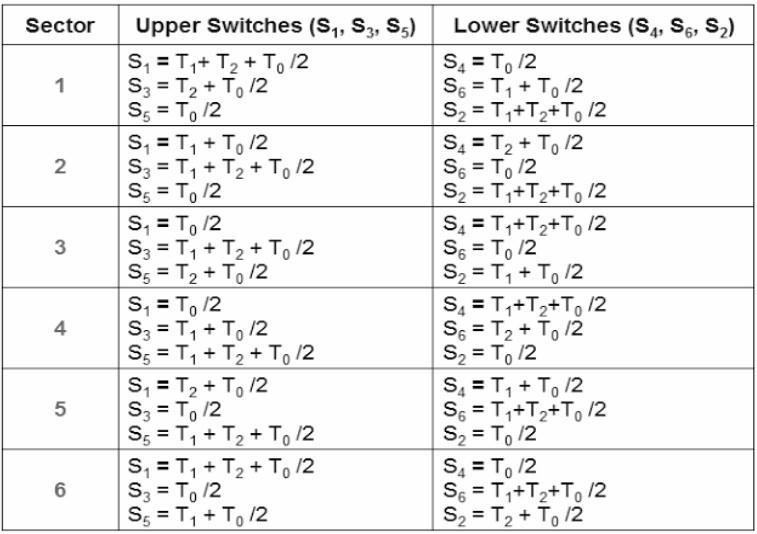
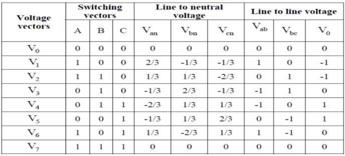
Table-3: Simulationparameters
Parameters Specification
StatorResistance 0087Ω
StatorInductance 08mH RotorResistance 1157٠RotorInductance 08mH MutualInductance 347mH Inertia 003Kg��2 FrictionFactor 01Nms PolePair 2
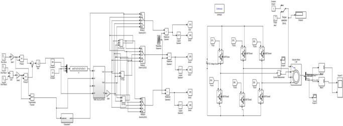
TheSpaceVectorPWMforVSIFedIM Driveissimulatedin MATLAB/SIMULINK by choosing the parameters listed in Table 3 and the Simulink model is shown in Figure 5. The gate pulse generation circuit is shown in figure 6. The gate pulse is generated by converting the three phase quantity into two phase quantity and then obtained Vref and angle. From there time period for each leg is calculated and comparedtogeneratethepulsesforeachswitches.
Fig5–SimulinkmodelofSVPWMbasedIMDrive
e-ISSN:2395-0056 Volume:09Issue: 11 | Nov 2022 www.irjet.net p-ISSN:2395-0072 Table1-SwitchingstatescorrespondingtoSpaceVector Figure4–Spacevectorsequences
International Research Journal of Engineering and Technology (IRJET) e-ISSN:2395-0056 Volume:09Issue:11 | Nov 2022 www.irjet.net p-ISSN:2395-0072
ThesimulationresultsoftheSpaceVectorBasedHysteresis Controller for VSI Fed IM Drive are shown in the following figures. Three phase Input voltage is shown in figure 7 to obtain SVPWM. Simulation is carried out by using 1HP motorandparametersarecalculatedbyusingNo-loadand blockedrotortest.
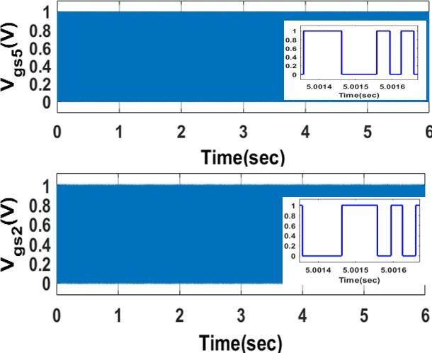
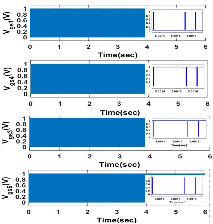
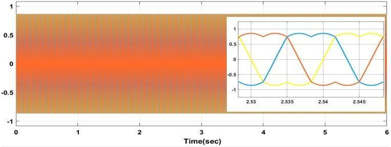
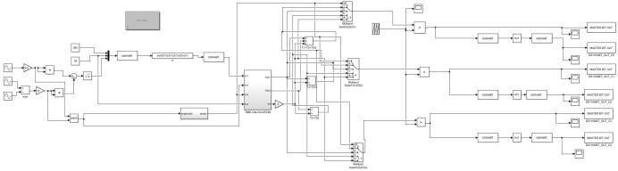
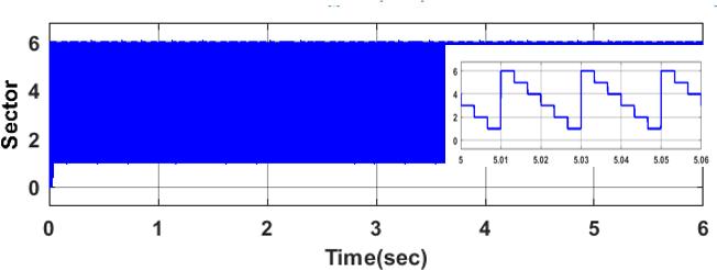
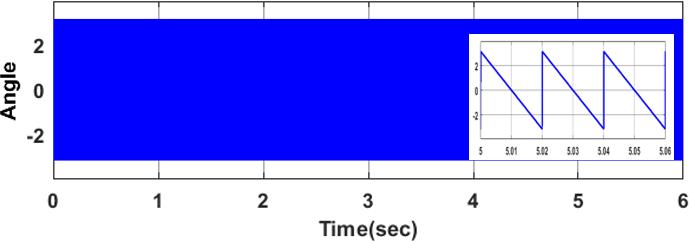
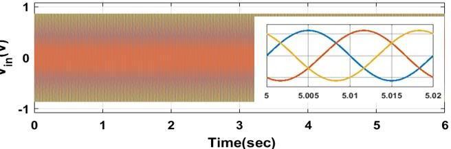
Figure7-Inputvoltage
Figure8-Angle
Figure9-Angletosector
The three phase quantity is converted into two phase quantitybyclarkstransformation.Andfromthetwophase quantity, Vref and angle is obtained . The angle obtained is shown in Figure 8. Figure 8 shows the conversion of angle to sector where angle is converted to 6 sectors. Figure 10 showsthespacevectorPWM.
International Research Journal of Engineering and Technology (IRJET)
e-ISSN:2395-0056
Volume:09Issue:11 | Nov 2022 www.irjet.net p-ISSN:2395-0072
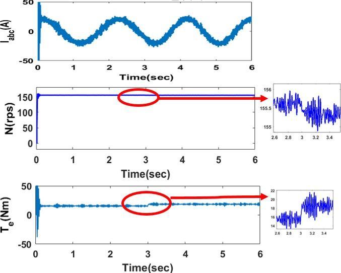
Figure 13 shows the operation of motor at no load condition. Intially motor is started at no load and a load torque of 5 Nm is applied at t = 3 seconds by means of a step input as shown in Figure 14. The speed is reduced whenloadtorqueisapplied.Thetorqueisincreasedfrom 15Nmto18Nmwhenthetorqueisapplied.
Figure15–SimulinkmodelwithHysteresis
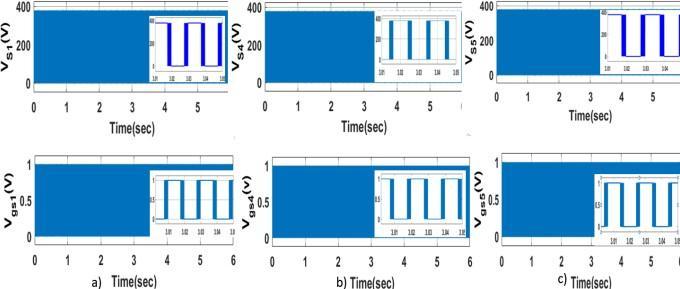
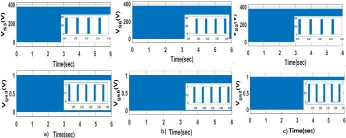
The simulation results of the Hysteresis controller BasedVSIFedIMDriveareshowninthefollowing figures. Simulation is carried out by using 1HP motorandparametersarecalculatedbyusingNoload and blocked rotor test. Figure 16 shows the stator current and three phase reference current . The stator current and three phase reference current are given to a hysteresis controller with a band of 0.1. The output of hysteresis controller is given as the pulses for each switches. The voltage across the switch and gate pulse to S1 , S4 and S5
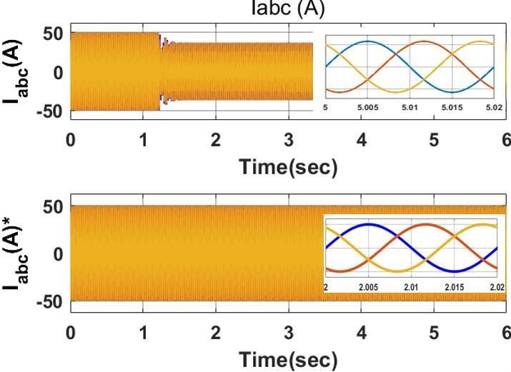
areshownintheFigure17.Thevoltageacrossthe switchandgatepulsetoS3 ,S6 andS2 areshownin theFigure18.
Figure13–Operationwithload
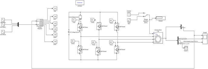
TheHysteresiscontrollerbasedVSIFedIMDriveis simulated in MATLAB/SIMULINK by choosing the parameters listed in Table 3 and the Simulink modelisshowninFigure15.
Figure16–StatorcurrentandReferenceCurrent Figure 17:
International Research Journal of Engineering and Technology (IRJET) e-ISSN:2395-0056 Volume:09Issue:11 | Nov 2022 www.irjet.net p-ISSN:2395-0072
Figure18:a)VoltageacrossswitchS3andGatepulse toS3b)VoltageacrossswitchS6andGatepulsetoS6 c)VoltageacrossswitchS2 andGatepulsetoS2
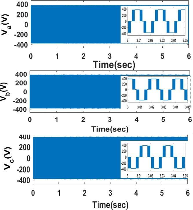
Figure18-PhaseVoltages
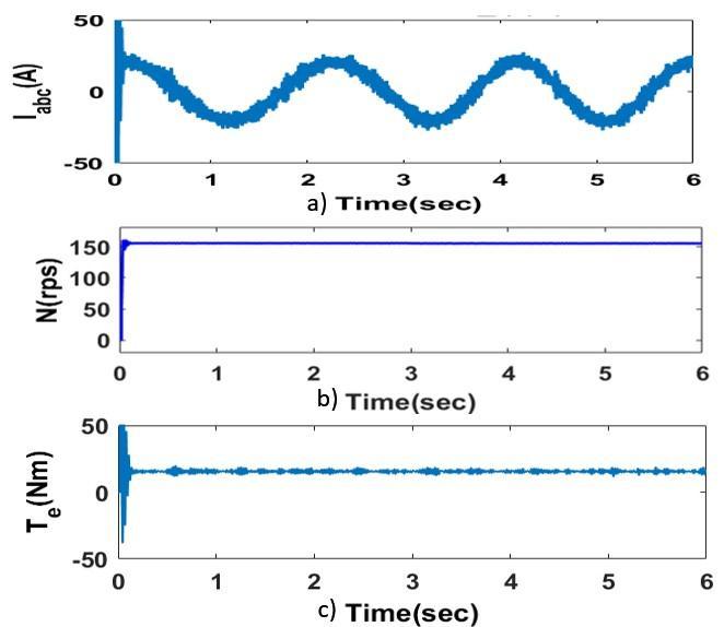
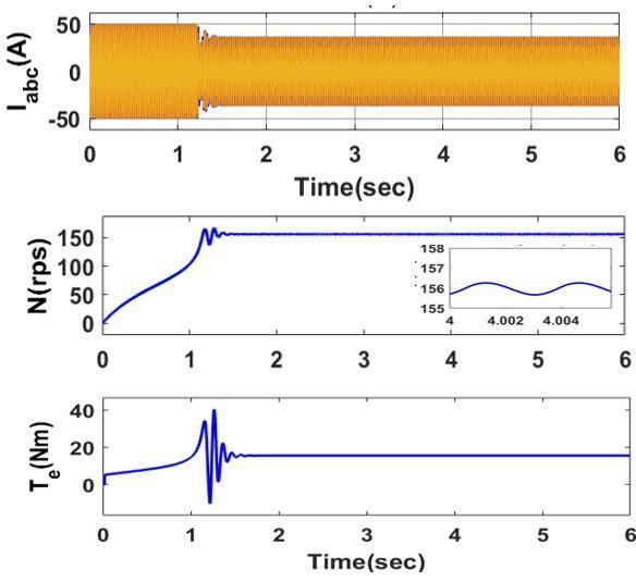
The phase voltages of inverter is shown in Figure 18 which has maximum value of 400V. The motor current, the speed of motor and motor torque at no load are given in Figure 19. It can be seen that we are getting a constant speed of 157 rps and motor torqueis 15 Nm as shown in Figure 19 . Under loadcondition,aloadtorqueof3Nmisapplied.
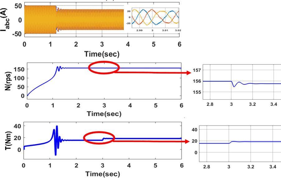
Under load condition, a load torque of 5 Nm is applied at t = 3 second by means of a step input as shown in following Figure 20. When load is applied the currentisdecreasedand thereisadipinspeed at t = 3 sec . The tracking time to attain constantspeed is less than 0.2 sec with a speed error of0.1rps . Starting torque of motor is high and decreased when speed is attained. The torque is of15 Nm. It is then increased to 18Nmwhenloadisapplied.
The FFT analysis is carried out with a switching frequency of 50Hz. The THD of output current is observed as 7.17 for SVPWM and 19.39 percent for the hysteresis controlled. THD of output voltage is also analyzed. THD of output voltage for SVPWM and Hysteresisare2.09and25.69percent.So,itisobserved that the THD of hysteresis controlled is higher than the SVPWM controlled for both
International Research Journal of Engineering and Technology (IRJET) e-ISSN:2395-0056
Volume:09Issue:11 | Nov 2022 www.irjet.net p-ISSN:2395-0072
Figure21-THDoftheoutputCurrenta)SVPWM
[THD = 7.17 percent] b) Hysteresis controller [THD=19.3percent]
Figure 22: THD of the output Voltage a) SVPWM [[THD = 2.05 percent]] b) Hysteresis controller [THD=25.6percent] SwitchingPulse
Also observed the switching pulse of SVPWM and hysteresis controlled for 0.0003 sec and analyzed that switching pulse of hysteresis is more than thatof SVPWM controlled IM drive. There are 14 switching for a time period of 0.001 sec in SVPWM method and for the same time period there are 44 switchingforHysteresiscontrolled.
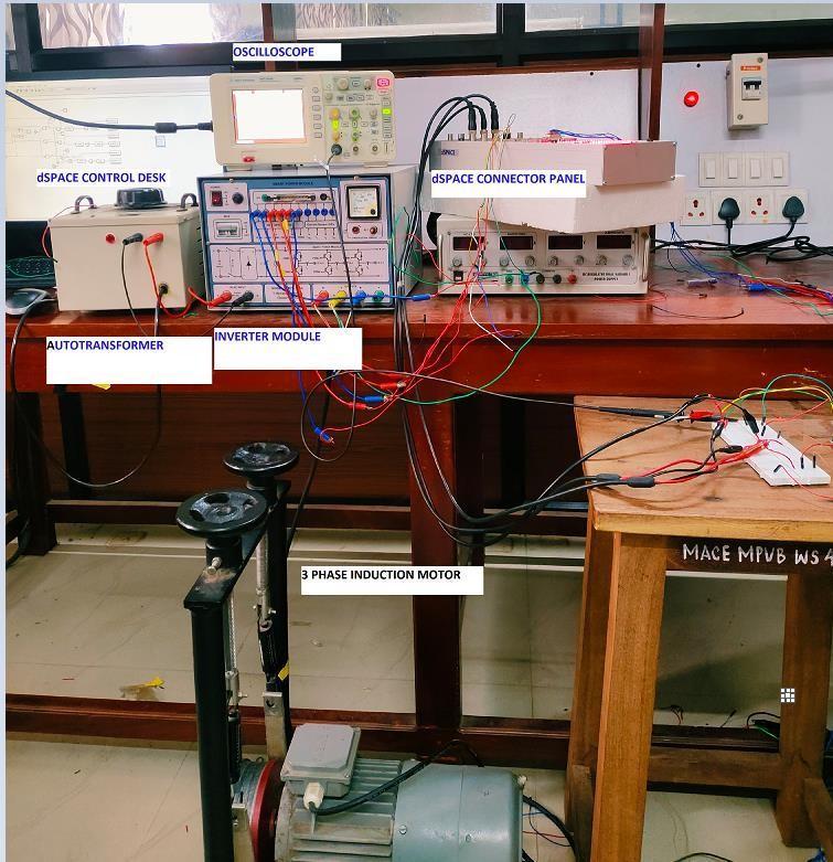
Figure 23: Switching Pulses a)SVPWM b) Hysteresiscontroller
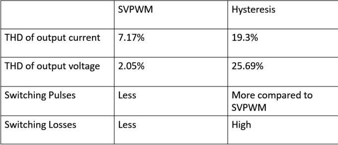
Table4 -Comparison between SVPWM and Hysteresis
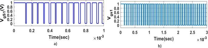
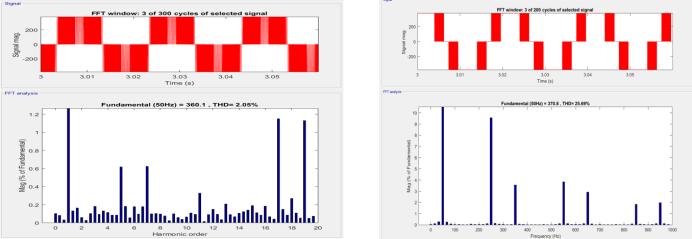
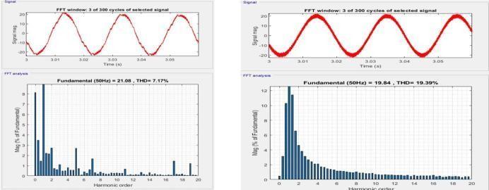
Table 4 shows the comparison between SVPWMand Hysteresis controlled modulation technique. It is observed that THD of output current and switching pulses of SVPWM is less compared to Hysteresiscontrolled. REAL
With Real-Time Interface (RTI), you can easily run your function models on the DS1104 R and D Controller Board. You can configure all I/O graphically, insert the blocks into a Simulink block diagram, and generate the modelcodeviaSimulinkCoder. The real-time model is compiled,downloaded, and started automatically. This reduces the implementation time to a minimum. The experimentalsetupisshownbelow.
International Research Journal of Engineering and Technology (IRJET) e-ISSN:2395-0056
Volume:09Issue:11 | Nov 2022 www.irjet.net p-ISSN:2395-0072
For making simulink model, a svpwm is compared with repeatingsequenceandtheoutputisgiventomaster bit out block. For 6 switches theoutputpins are given as C0 to C5 and the output of pulse is taken from digital I/O connector from dspace connector panel. Figure 24 shows the simulinkMasterbitoutblocks.Theswitching pulseofS1andS4(firstleg),S3andS6(ofsecondleg),S5 andS2(ofthirdleg)isshowninFigure.SwitchS1,S4,S3, S6,S5andS2hasafrequencyof3kHz.
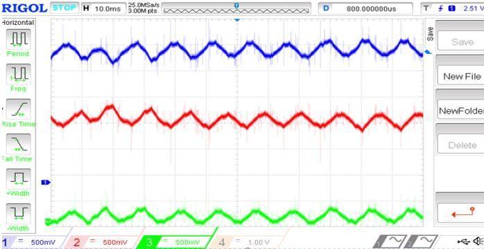
Motor current of phase A in open loop is shown in Figure 27. The other two are 120 degreephaseshiftedas showninFigure27.
Figure25–GenerationofswitchingPulse
shows the simulink model of Pulse Generation of Switches using Master bit out blocks. The switching pulse ofS1 andS4 (firstleg),S3andS6(ofsecondleg), S5 and S2 (ofthirdleg)isshowninFigure26:(a),(b),(c) respectively. Switch S1, S4 , S3, S6 , S5 andS2 hasafrequencyof3kHz.
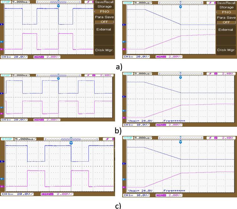
Figure27-CurrentwaveformIa,Ib andIc
A Matlab/Simulink model is done to implement SVPWM for three-phase VSI. The VSI model isbased on space vector representation. Current control is done by hysteresis current controller. Vector control and hysteresis control of inductionmotor drive is simulated.
Speed of motor was maintained constant at varying load using SVPWM control. Studied the switching frequency variation, losses for SVPWM and hysteresis based IM drive. Analysed the total harmonic distortion of output current, voltage and switching pulses for both SVPWM and hysteresis controlled IM drive. Hardware implementation is done with dSPACEds1104 controller.
[1] Sandeep Jayaprakasan, Ashok S., and Rijil Ramchand,”Current Error Space Vector Based Hysteresis Controller for VSI Fed PMSM Drive, IEEE Trans. Power Electron., Vol. 35, No. 10, October2020.
[2] M. P. Kazmierkowski and L. Malesani, ”Current controltechniquesforthree-phasevoltage-source PWM converters: A survey”, in IEEE Trans. Ind. Electron.,vol.45,no.5,pp.691703,Oct.2000.
Figure 26- Switching Pulses and dead time for switchesa)S1,S4 ,b)S3,S6 andc)S5 ,S2
The pulses for first leg that is for the switch 1 and 4 anddead time of 20 msec are shown in figure 26. The pulses are 180 degree out of phase. The pulses to the switch 3 and 6 and dead time of 20 msec are shown in figure 26 (b) and The pulses to the switch 5 and 2 and dead time of 20 msec areshowninfigure26(c).Figure5.6 showsthecurrentwaveform.ofmotorforthethreephases.
[3] P.Tekwani,R.Kanchan,andK.Gopakumar,”Novel current error space phasor based hysteresis controller using parabolic bands for control of switching frequency variations,” in IEEE Transactions on Power Electronics,vol. 54, no. 5,Oct.2007.
[4] R. Ramchand, K. Gopakumar, C. Patel, K. Sivakumar, A. Das, and H. AbuRub,”Online computation of hysteresis boundary for constant switching frequency current-error space-vector-
International Research Journal of Engineering and Technology (IRJET)
e-ISSN:2395-0056
Volume:09Issue:11 | Nov 2022 www.irjet.net p-ISSN:2395-0072
based hys teresis controller for VSI fed IM drives, IEEE Trans. Power Electron., vol. 27, no. 3, pp.15211529,Mar.2012.
[5] Joseph Peter , Srikar Krishnatheeram and Rijil Ramchand,”Novel Hysteresis Regulation Strategy for a Two-level Inverter Fed Induction Motor Drive to Achieve Nearly Constant Switching Frequency,, IETE Journal of Research,, vol. 41, no. 1,pp.9196,Feb.1994.,Aug.2015.
[7] M. Baiju, K. Mohapatra, R. Kanchan, P. Tekwani, and K. Gopaku mar A space phasor based current hysteresis controller using adjacent inverter voltagevectors withsmoothtransitiontosixstep op eration for a three phase voltage source inverter, IEEE Trans. Power Electron.,vol. 15, no. 1, pp.3647,2005.
[8] Srikanthan Sridharan and Philip T. Krein, Fellow, MinimizationofSystem-LevelLossesinVSI-Based Induction Motor Drives: Offline Strategies, , IEEE Transactions onIndustry
[6] A. Consoli, S. Musumeci, A. Raciti, and A. Testa,”Sensorless vector and speed control of brushlessmotordrives,IEEETrans.Ind.Electron., vol.41,no.1,pp.9196,Feb.1994.,Aug.2015. 2016.
[9] V. M. Mistry, S.Waiker, K. Gopakumar, L. Umanand, and V. Ranganathan,V. M. Mistry, S.Waiker, K. Gopakumar, L. Umanand, and V. Ranganathan, A multi axis space phasor based current hysteresis controller for PWM inverters,EPEJ,,vol.10,no.1,pp.1725,2000. © 2022, IRJET | Impact Factor value: 7.529 | ISO 9001:2008 Certified Journal