International Research Journal of Engineering and Technology (IRJET) e-ISSN:2395-0056

Volume: 09 Issue: 11 | Nov 2022 www.irjet.net p-ISSN:2395-0072
International Research Journal of Engineering and Technology (IRJET) e-ISSN:2395-0056
Volume: 09 Issue: 11 | Nov 2022 www.irjet.net p-ISSN:2395-0072
1 , M.Anand Reddy2 , G.ArunKumar3
1,2Final Year students, Department of Mechanical Engineering, 3Professor, Department of Mechanical Engineering, 1,2,3Sathyabama Institute of Science and Technology, Chennai, Tamilnadu, India-600119 ***
Abstract – The emergence of technologies such as power steering has helped make driving less burdensome on drivers and increased the pleasure of driving. Power steering systems practically always make use of fluid pressure as a means of assisting the driver in turning the front wheels of the vehicle. The application of air pressure is the driving force behind the operation of pneumatic devices and equipment. Pneumatic systems are any tools or gadgets that make use of air in their operation. This type of apparatus runs at a high pressure. Compressed air is used to power an air-operated actuator, which is used to circulate the machine. The control has an instantaneous impact on the air. It was dispersed throughout the system via the tubes and valves. Two wheels, a pneumatic actuator, and a connection for power steering have all been part of this system, which is mounted on a frame. Every single wheel is attached to the shaft of the pneumatic actuator that controls them. The second wheel is connected to the first. Mounting the pneumatic cylinder stroke, which causes steering, is controlled by the direction control lever. The Pneumatic Power Steering System of the car makes driving it very simple, which are already fluid-powered and lowmaintenance
Key Words: Pneumatic actuators, Pneumatic Transmission of energy, Wheels, Pneumatic control valve, Links, Solenoid valve
Manytoolsandpiecesofequipment,includingautomobiles, have pneumatic steering. Heavy machinery is frequently used as an illustration. Under direct or automatic control from control valves, high-pressure compressed air is supplied throughout the steering system to various pneumaticactuatorsandcylinderswiththeaidofhosesand tubes.Pneumaticdrivesarealsosimpleandaffordable[1]. Due to the pneumatic control system's reliance on compressedair,itmustbemadeaccessibleinanamountand atapressureappropriatetothesystem'scapabilities[2].An effectiveandsecurewaytoautomateaproductionlineisto make pneumatically powered components. The project's scope included the creation and construction of a compressedairtestplatformthatcouldduplicateanumber ofoperations[3].Theairflowthroughthepipeinpneumatic systems is simulated using a linear differential equation
basedonNewton'ssecondlaw,accountingfortheinertial effectsoftheair,friction,andlocalpressurevariations[4]. The dynamical link between the actuating forces and a PLSA'stwomaindegreesoffreedom,bendingandsteering, is directly determined using the general PLSAs [5]. The dynamicallinkbetweentheactuatingpressuresandthetwo fundamental degrees of freedom of a PLSA, bending and steering,isderivedusingtheGeneralPLSAsinaparameterindependentmanner[5].Thecyclicalstorageofexhaustair fromafewoutletsofanindustrial-scalearbitrarypneumatic machineoutputisbeingexpandedinordertoimprovethe energy efficiencyofpneumaticmachines[6].Toautomate theregulationoftheproportionatesupplyofnaturalgas[7]. The combination of compressed gas energy storage and a nonlinear cam transformation mechanism results in the proposalofanovelisobariccompressedairstoragesystem. Results indicate that this novel isobaric compressed air storagedeviceperformswellintermsofenergyuseandhas favourableconstant-pressureproperties[8].Multiple-joint, multi-DOF forceps manipulators have been developed by businessesandresearcherstomakedoctorslessemployable [9]. The design and approval of a pneumatic push-pull actuatorforvibrationisolation,aswellasthedevelopment ofauniquecontrollawforanautonomousvehicle[10].An investigationofthedynamicfeaturesofsystemsusingboth experimentation and analysis [11]. The development of equations to describe the steering wheel's and the front wheels' two-degrees-of-freedom rotations around the kingpin[12].ThisstudysuggestsaH/extensioncontroller basedonanactivefrontsteeringsystembycombiningthe extension control into the H mixed sensitivity control regarding sensitivity f. The control's objective is to keep lanes open while adhering to a number of constraints, including actuator saturation of the steering system, an unidentifiedroad'scurvature,andanundeterminedlateral wind force [13]. The force-balance idea and its use of pneumaticcontrols,therolesoftemperatureandpressurein these systems, and the usage of spring range to sequence valvesanddampersareall covered[14].Accordingtothe force-balanceprinciple,theenclosureorchambercontains threeaperturesorports:oneforthesupplyairintake,one fortheoutputofthecontrolsignal,andonefortheexhaust [15].Pneumaticcontrolvalvefrictionissuesweresomewhat frequent. The basic pneumatic control valve components, suchasthevalvepositioner,valveactuator,andvalvebody, serveasthefoundationforthenewsemi-physicalmodelfor
Factor value: 7.529 | ISO 9001:2008 Certified Journal |
International Research Journal of Engineering and Technology (IRJET) e-ISSN:2395-0056
Volume: 09 Issue: 11 | Nov 2022 www.irjet.net p-ISSN:2395-0072
stickypneumaticcontrolvalvesproposedinthisstudy[16]. In terms of space efficiency, engine economy, and environmental friendliness, electric power steering (EPS) systems offer a number of advantages over conventional hydraulic power steering. To generate various steering sensations, lessen driver-exercised steering torque, and enhance return-to-center performance, an EPS control algorithmwasdeveloped[17].Alloftheauxiliarysystems typically seen in heavy-duty vehicles (such the power steeringpumpandairconditioningcompressor)areenginedriven, which significantly restricts their performance. Engine speed influences energy consumption as well as outputs (such speed and temperature), even though most auxiliaryrequirementsareunrelatedtoenginespeed[18]. When used, electromagnetic solenoid valves' (SVs) fundamental properties suchasreliability, effectiveness, andremainingusefullife(RUL) regulatetheiroperationin a safe and effective manner [19]. The design and mechatronicrequirementsforanelectricalpowersteering simulator. In addition to being portable and modular, the simulator'sarchitectureisasidenticalasitispossibletobe, and its steering mechanism is comparable to that of a genuinecar[20].UsingalinearquadraticGaussian,thebest controlstrategyforthetractor'ssemi-activesuspensionis created.Thesimulationmakesuseofadetailedautomotive model as well as a hydro-pneumatic suspension system model created with Simulation X and MATLAB/Simulink [21].Thepower-assistedsteeringsystemisanimprovement in automotive dynamics that increases driver comfort by loweringsteeringeffortandrespondingmoreswiftlythana traditionalmanualsteeringsystem.
Liftingairpressurefromlowtohighisthemaingoalof a pneumatic power steering system. This can be done by reducingtheairflow.Pushingthesolenoidvalve'slevertoits leftsideallowsairtoflowthroughapneumaticcylinder,as aircompressorsaretypicallypositivedisplacementdevices. Therearefiveopeningsandthreepositionsonthissolenoid valve.Thereisoneintakeport,twodischargeports,andtwo venting apertures. In the two extreme positions, you can only modify the orientation, but in the middle, nothing changesintermsofitsactualform.Therearetwowiresthat connecttheactuatortotheinletandoutletports(Cylinder). Through the actuator valve, pressurised air can enter the cylinderblock'sfrontend.Theairpressureisusedtodrive the piston backwards during the recovery stroke. At the conclusionofthecuttingstroke,airfromthesolenoidvalve enters the cylinder block from behind. The control valve keeps the pressure steady while decreasing the available surface area. Consequently, the piston is subjected to a greateramountofpressureandisabletotravelatafaster rate,resultinginashorterreturnstroke.Twodifferenttypes of compressors are used, one of which is a tiny air compressor and the other a larger, two-stage compressor
unit.Compressedairisfedintothesolenoidvalvefromthe compressor. Solenoid valves are used to control flow in responsetosignalsfromatimingdevice.Itisequippedwith amotor,apulleydrive,apressureregulator,andpressurised air tanks that can be used in a hurry. When the predeterminedpressureissurpassed,theexcessairisletout throughareleasevalve.Thecompressorhasa10HPengine andisdesignedtoworkatpressuresof145-175PSI.When air enters the air fitter from the compressor, it is compressed. It's filtered out all the microscopic dust particles.Therefore,pneumaticsystemsareusedtoregulate thepowersteering.
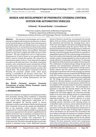
1. PneumaticCylinder-Materials(STEEL,ALUMINIUM STAINLESSSTEEL,BRASSetc..)
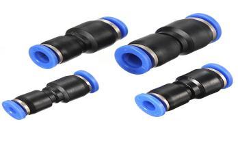
2. 5/2 double acting Solenoid Valve - Materials (Nylon, PVC,NICKEL PLATED BRASS AND STAINLESSSTEEL)
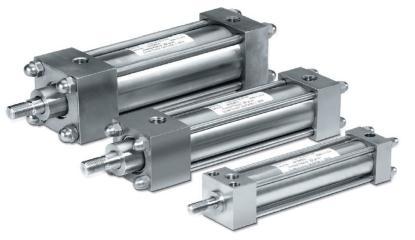
3. Connectors - Materials(Polypropylene is a thermoplastic)
4. Hoses - Materials(Aluminium,plastic,Rubber, pvc)
5. SuctionCupsandVaccumGenerator - Materials( pvcplasticorneoprenemildsteel)
Devicesknownaspneumaticcylindersareabletotransform the potential energy of compressed air or gas into a mechanical motion that may then be used to drive one or morefinalcontrolelements.AsshowninFig.1.
Thedouble-actingpneumaticactuatorstypicallyuse the 5/2 and 5/3 solenoid valves for directional control. Single-coil5/2valvesoftenuseareturnspringorpilotair whenthepoweriscut.Doubleactingsolenoidvalvescanbe made from a variety of materials including nylon, PVC, nickel-platedbrass,andstainlesssteel.AsshowninFig.2.
International Research Journal of Engineering and Technology (IRJET) e-ISSN:2395-0056
Volume: 09 Issue: 11 | Nov 2022 www.irjet.net p-ISSN:2395-0072
In order to attach compressed air tools to a compressed air line, pneumatic connectors are employed. Pneumaticcouplersmakeiteasytoconnectanddisconnect tools from pressurised hoses and pipes. Connectors are constructedoutofPolypropylene.
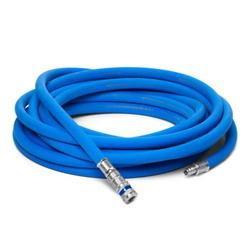
Compressedairtravelsthroughhoses,whichare flexibletubes.Aluminum,plastic,rubber,polyvinylchloride, and other synthetics are all common choices for hose manufacturing.AsshowninFig.4.
When it comes to low-cost mechanisation, pneumatic is a preferred medium, especially for repetitive or sequential operations.Power(orenergy)andcontrolcanbesupplied throughcompressedairsystems,whicharealreadypresent in many businesses and buildings (although equally pneumatic control systems may be economic and can be advantageouslyappliedtootherformsofpower).Themain advantagesofanall-pneumaticsystemareoftenitslowcost and ease of use, the latter of which requires almost no maintenance. Furthermore, it may have massive social benefits.Thesteeringsystemusespneumaticsorsomeother formofenergytransmissiontoaccomplishthegiventask.To dowork,itisnecessarytoapplykineticenergytoaresistive object, which causes the object to move over a distance. Compressed air is utilised to store potential energy in a pneumatic system. Pneumatic systems convert potential energystoredincompressedairintousefulworkforcewhen the air is released for expansion (kinetic energy and pressure).Pneumatictransmissionofworkenergyrequires strict regulation and management at all times. No useful work will get done unless restraints are applied, and machineusersriskinjuryiftheyaren't.Usingvalves,energy transmittedbypneumaticscanbeeasilyregulated.
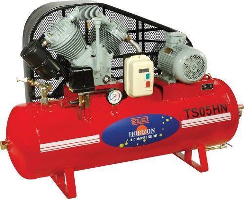
Compressedaircomesfromamachinecalledanair compressor.InaccordancewithFig.5.Thesestoragetanks havepressure-reliefvalvesinstalledincaseofanexplosion.
TheequationVr=14.7(QrQC)Pmincanbeusedtocalculate thereservoir'soptimalsize.
International Research Journal of Engineering and Technology (IRJET) e-ISSN:2395-0056
Volume: 09 Issue: 11 | Nov 2022 www.irjet.net p-ISSN:2395-0072
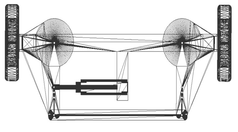
The wheels, pneumatic actuator, and frame, among other components,maybeseeninthefrontviewofthepneumatic powersteeringsystem.….Asshowninthefigure.6
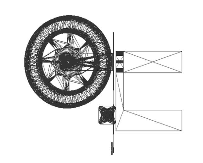
Wheels, a pneumatic actuator, a frame, and other components make up the pneumatic power steering system'srightview.accordingtothefigure.7
International Research Journal of Engineering and Technology (IRJET) e-ISSN:2395-0056
Volume: 09 Issue: 11 | Nov 2022 www.irjet.net p-ISSN:2395-0072
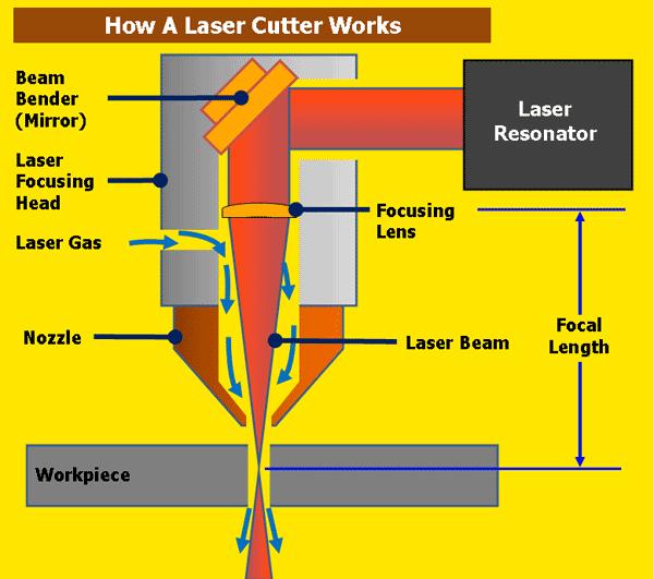
and the ability to carve intricate shapes and microscopic holes.
Mostpeopleknowthat"LASER"referstoLightAmplification by Stimulated Emission of Radiation. The laser beam is a narrow, intense shaft of light with a certain colour and wavelength. In a standard CO2 laser, this phenomenon happens in the infrared portion of the light spectrum, making it invisible to the naked eye. From the laser resonator,whichproducesthebeam,thebeam'sdiameteris about3/4ofaninch;thisisaboutthesamediameterasthe beamasittravelsalongthemachine'sbeampath.Itmayfirst bereflectedoffofaseriesofmirrorscalled"beambenders" before being focussed onto the plate. The laser beam is guidedthroughanozzle'sborebeforeitreachestheplate. Throughthatnozzleboreisalsocomingacompressedgas likeoxygenornitrogen.
Drillingisaformofcuttingwhereacircularholeis boredoutofasolidobjectusingadrillbit.Typically,thedrill bit is a revolving, multi-pointed cutting tool. The bit is pressedagainsttheworkpiecewhilespinningatspeedsof severalhundredtoseveralthousandrevolutionsperminute. This pushes the cutting edge toward the workpiece by removing chips (swarf) from the hole while it is being drilled.
When drilling into rock, it is common practise to spin the bit, however this does not necessarily result in a circular cut. A drill bit is often hammered rapidly into the holeseveraltimestoformthehole.Top-hammerdrillshave hammeringmechanismsonboththeinsideandtheoutside ofthebit,allowingfordrillinginbothdirections(down-thehole drill, DTH). Drifter drills, often known as horizontal drilling rigs, are specialised tools used to bore horizontal holes.
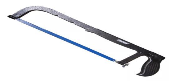
Ahacksawhassmall,sharpteethandwasfirstandforemost designed forcuttingmetal.Similarsaws,calledbowsaws, arealsousedtocutwood.
Hacksaws, a type of hand saw, typically have a C-shaped frame that compresses a blade. Hacksaws like these have pins on the handle (often shaped like a pistol grip) that secure a short, disposable blade. The frames may be adjustablesothatdifferentsizedbladescanbeused.Ascrew orothermechanismisusedtomaintaintensiononthethin blade.Likemostframesaws,hacksawsincludeabladethat canbeadjustedsothattheteethfaceeithertowardoraway fromthehandle,allowingthesawtobeusedforcuttingon either the push or pull stroke. When sawing horizontally downward while holding the work in a bench vice, the hacksaw blade is often placed so that the cutting edge is facingfront.
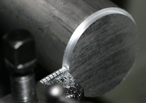
Turning is a type of machining in which a cutting tool (usuallyanon-rotarytoolbit)movesalongahelicaltoolpath as the workpiece rotates. Tools' axes of motion are essentiallylinear,eveniftheymaybealongastraightline,a sequence of curves, or an angle (in the non-mathematical sense).Conventionally,theterm"turning"isusedtoreferto the process of creating external surfaces via this cutting action,whiletheterm"boring"isusedtorefertotheprocess of creating internal surfaces via this same fundamental cuttingaction(thatis,holesofvarioustypes).Asaresult,the term "turning and boring" is used to describe a broader groupof(roughlyanalogous)lathingoperations.
International Research Journal of Engineering and Technology (IRJET) e-ISSN:2395-0056
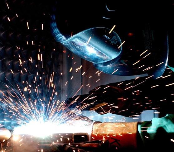
Arc welding is a method of combining metals in which electricityisusedtoprovideenoughheattomeltthemetal, which is then allowed to cool and congeal as a joint. By strikinganelectricarc betweenanelectrodeandthebase material,aweldingpowersupplyliquefiesthemetalsatthe weldingspot.Directcurrent(DC)oralternatingcurrent(AC) canbeused,andeitherdisposableorpermanentelectrodes canbeused.Weldingareasaretypicallyshieldedusinggas, mist,orslag.Arcweldingprocedurescanbefullyautomated, semi-automated,orperformedbyhand.Althoughtechnique wasn'twidelyadopteduntilafterWorldWarII,arcwelding's origins may be traced back to the second half of the 19th century.Itisstillanessentialprocessinthemakingofsteel structuresandvehicles.
[5]J.S.Leszczynski,D.Grybos,”Compensation(2019),ForThe Complexity And Over-Scaling In Industrial Pneumatic SystemsByTheAccumulationAndReuseOfExhaustAir”32
[6] Osinski Yuriy, Danilov Vadim (2019)”Oscillatory Step RotaryPneumaticDrivesInGasAndTransmissionSystems
[7] Hu Wang, Zhengren Tong,Xin Dong,Wei Xiong,David Sk.Ting,Rupp Carriveau,Zhiwen Wang(2021)Design And EnergySavingAnalysisOfANovelIsobaricCompressedAir StorageDeviceInPneumaticSystems,3,139-141
[8] Katsuhiko Fukushima(2021) A Pneumatic Rotary ActuatorForForcepsTipRotation
[9] M Damira, M Abou-Alia, A Damirb (2021) Pneumatic Non-Contact Measuring System For In-Process Dimension Measurements
[10] Christiangraf , Rudiger, Kieneke(2010)”Pneumatic Push-PullActuatorForAnActiveSuspension,74,112-114
[11] Masato Abe(2015).Steering System And Vehicle Dynamics,5.1,139
[12] Anh-Tu Nguyen, Chouki Sentouh, Jean-Christophe Popieul(2016).Takagi-SugenoModel-BasedSteeringControl ForAutonomousVehiclesWithActuatorSaturation,49,206211.
We'vedeterminedthatthepneumaticallypoweredsteering mechanismisanexceptionallyuniqueandeasymethodof controlling the vehicle. This pneumatic steering system is easytooperateinbothsmallandlargetrucks.Thisisaform of protection for both the present and the future. This pneumaticsteeringsystemfreesupmorespacefortheair bagtoperformitsfunction.
[1] “PneumaticPowerSteering”ParthLad,VaibhavWani, PranitMehata(2014),2349-5162
[2] “DesignAndImplementationOfAnEnergyMonitoring Physical Systyem In Pneumatic Automation,”2000,Kyle Abela,Paulrefalo,EmmanuelFrancalaza
[3] “Modeling And Optimization For Pneumatically Pitchiner Connected Suspensions Of A Vehicle “(2018),HengijaZhu,JamesYang,YunqingZhang
[4]“AUnifiedSystemIdentificationApproachForAClassOf Pneumatically-Driven Soft Actuators”(2001), Xiaochen Wang,TaoGeng,YahyaElsayed,ChakravathiniSaaj,Constant inaLekakou
Volume: 09 Issue: 11 | Nov 2022 www.irjet.net p-ISSN:2395-0072 © 2022, IRJET | Impact Factor value: 7.529 | ISO 9001:2008 Certified Journal | Page187
[13]Wanzhongzhao,Milan,Chunyanwang,Zhilingjin,Yufang Li(2019),”ExtensionStabilityControlOfAutomotiveActive FrontSteeringSystem”
[14]Montgomery,R.Mcdowall.(2008)”PneumaticControls FundamentalsOfHvac”180,17-25.
[15]LiTang,LeiFang,JaindongWang,QunilShang(2015). “ModelingAndIdentificationForPneumaticControlValves WithStiction”1244-1249,48-28
[16]Ji-HoonKim,Jae-BokSong(2002).ControlLogicForAn ElectricPowerSteeringSystemUsingAssistMotor,447-459, 12-3.
[17] Emilia Silvas, Eric Backx, Theo Hofman, Henk Voets (2014)”DesignOfPowerSteeringSystemsForHeavy-Duty Long-HaulVehicles”3930-3935,47-3.
[18]SantoshV.Angadi,RobertL.Jackson(2022).ACritical View On The Solenoid Valve Reliability, Performance And Remaining Useful Life Including Its Industrial Applications.36-14
[19] L.Nehaoua, A.Marouf, J.J.Santin, P.Pudlo, M.Djemai (2016). Towards An Electrical Power-Assisted Steering Simulator:ModelingSpecifications.86-62
International Research Journal of Engineering and Technology (IRJET) e-ISSN:2395-0056 Volume: 09 Issue: 11 | Nov 2022 www.irjet.net p-ISSN:2395-0072
[20]Kyuhyun Sim, HwayoungLee, Ji Won Yoon, Sung-HoHwang(2016).EffectivenessEvaluationOfHydro-Pneumatic AndSemi-ActiveCabSuspensionForTheImprovementOf RideComfortOfAgriculturalTractors.69,23-32
[21]B.U.Raja Ramakrishna, S. Murali(2021).Design And ModellingOfEmergencyPowerSteeringSystemForHeavy Vehicles,101,10-15
2022, IRJET | Impact Factor value: 7.529 | ISO 9001:2008 Certified Journal |